Tailoring optical pulling forces with composite microspheres
Abstract
Optical pulling forces or tractor beams can pull particles against light propagation by redirecting the incident photons forward. This is typically achieved using Bessel beams with very small half-cone angles, which considerably limits its applicability. One can circumvent such issue by using a superposition of plane waves. In order to investigate optical pulling forces exerted by a pair of non-colinear plane waves, we develop a theoretical framework based on Mie theory, Debye potentials and Wigner rotation matrices. We apply this framework to calculate the optical pulling force on metallo-dielectric composite particles, which we put forward as an alternative material platform to optimize and tailor tractor beams. Indeed we demonstrate that by adding a few plasmonic inclusions to low-refractive index dielectric particles of arbitrary sizes, we are able to produce polarization dependent optical pulling forces that cannot occur in the corresponding homogeneous particles. Altogether our findings not only provide innovative theoretical methods to compute optical pulling forces, but also provide new strategies to tailor and optimize them, paving the way to increase their applicability.
I Introduction
Light exerts radiation pressure on matter due to momentum exchange. Focused light beams exert an optical scattering force (forward force due to radiation pressure), as well as a gradient force (possibly along the backward direction) on small particles owing to the inhomogeneity of the electromagnetic field. As an example of application, in optical tweezers a tightly focused beam is used for optical manipulation Ashkin1970 ; ashkin1986 ; ashkin2006 ; Gieseler2020 and optical rotation Friese1998 ; grier2003 ; Lin2014 ; Diniz2019 ; Ali2020 with many applications fazal2011 ; Brzobohaty2015 ; Marago2018 ; Polimeno2018 .
On the other hand, a plane wave will always push a particle made of a passive medium along the forward direction. However, under certain conditions spatially structured beams can accelerate small particles along the direction opposite to the light propagation direction Lee2010 ; chan2011 ; Shvedov2014 ; chen2015 ; li2019 . Negative optical force or optical pulling force (OPF) occurs whenever illuminated particles are pulled towards the source due to the momentum conservation. In contrast to the trapping force in optical tweezers, the OPF can accelerate particles over a long distance without defining an equilibrium position. OPF has attracted considerable attention due to its many applications such as optical sorting Zhu2018 ; bowman , self-assembling, remote sampling Brzobohaty2013 ; Mazilu2012 , miniaturization of nanodevices lipson2009 and enantioselective manipulation Canaguier2013 ; Kun2014 ; bradshaw2014 ; wang2014 ; hayat2015 ; Kamandi2017 (see Ding2019 for a recent review). In particular, it was both theoretically and experimentally shown that nondiffracting Bessel beams can pull a sub-wavelength dielectric sphere chan2011 ; Brzobohaty2013 ; mitri2016 . Several approaches exist to demonstrate OPF on homogeneous dielectric spherical particles using bichromatic fields Krasnov2012 , multiple plane waves Liu2017 ; Mobini2018 and with optical gain Bian2017 ; Alaee2018 .
OPF can be achieved for weakly absorptive particles that maximize forward scattering while minimizing backward scattering chan2011 ; Liu2017 ; dogariu2011 ; Ding2019 . Typically, it is easier to pull high-refractive index particles, and even more so in the size range close to the laser wavelength Particles made of Si, Ge and GaAs can be pulled even when very small, with radii in the range because of the significant forward scattering and negligible backscattering due to the strong coherent interference between electric and magnetic dipoles Liu2017 ; Mobini2018 . In contrast, particles made of lower refractive index materials such as polystyrene or silica can only be pulled for relatively larger radii chan2011 ; Brzobohaty2013 .
The angular distribution of Mie scattering is clearly a key feature to achieve OPF. In that respect, progress in the fields of metamaterials and plasmonics now allows for novel strategies to tailor the interplay between electric and magnetic multipoles to produce directional Mie scattering chan2011 ; Liu2017 ; kall2018 . In particular, when considering composite microspheres, it is possible to minimize backscattering by tuning the filling fraction of inclusions Ali2018 ; Ali2020 .
In this work we show that metallo-dielectric composite microspheres, with metallic inclusions embedded in a low-index dielectric host, provide an optimal material platform that allows for pulling forces in a size range well below the laser wavelength, thus extending the applicability domain of OPF towards smaller sizes and lower refractive indexes. Specifically, we put forward a scheme using a superposition of plane waves, in contrast to the traditional approach that employs structured light beams. Our model describes the case of two collimated Gaussian light beams with beam waists much larger than the particle size thus leading to long-ranged optical forces. This is typically the case of paraxial beams as we consider sphere radii smaller or of the order of In order to consider our proposal, we develop a novel analytical framework to compute optical forces based on Mie theory, Debye potentials and Wigner rotation matrices, and apply it to situations such as the one depicted in Fig. 1.
This paper is organized as follows. Sec. 2 is devoted to the derivation of our theoretical formalism, which is based on Mie scattering theory combined with Wigner rotations. In Sec. 3, we present numerical results for the OPF on a metallo-dielectric composite. Finally, we summarize our findings and conclusions in Sec. 4.
II Optical force exerted by a superposition of plane waves on a Mie sphere
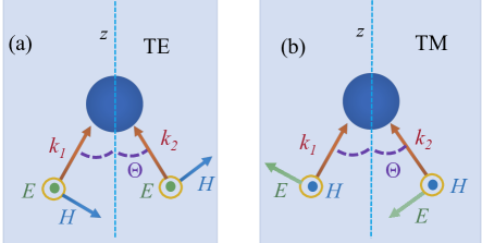
In the following we present our theoretical approach to the optical force on a microsphere. We consider a superposition of two linearly-polarized non-colinear plane waves, as indicated in Fig. 1. The corresponding wavevectors define the plane shown in Fig. 1, with respect to which we define transverse electric (TE) and transverse magnetic (TM) polarizations. We assume that both plane waves are linearly polarized along the same direction. The mixed case or a higher number of plane waves can also be considered within our formalism. In order to allow for arbitrary values of our approach is based on Mie scattering, implemented in terms of Debye potentials, and on Wigner rotations to build the desired scattering problem from the standard case of axial incidence.
We start by writing the electric field corresponding to the superposition of two incident plane waves propagating in the non-magnetic and non-absorbing host medium:
| (1) |
where the polarization unit vectors () are
| (2) |
The wavevectors
are written in terms of the speed of light in vacuum and of the host medium refractive index where is the relative permittivity. The spherical polar and azimuthal angles and define the propagation directions with respect to the -axis. When discussing specific examples, we will take and for TM and and for TE polarization as depicted in Fig. 1.
We introduce the electric (E) and magnetic (M) Debye potentials Bowkamp1954 ; Bobbert1986
| (3) | |||||
| (4) |
The electric and magnetic fields can be written in terms of the Debye potentials as follows:
| (5) | |||||
| (6) |
where and are the vacuum permittivity and permeability, respectively.
In order to derive the Debye potentials for a given plane wave, we first consider a ‘primed’ coordinate system such that the and axes coincide with the propagation and polarization directions, respectively. In such system, we find (omitting the time dependence from now on)
| (7) |
The Debye potentials of a plane wave in the primed coordinate system are then obtained from Eqs. (3), (4) and (7) by expanding in terms of spherical waves:
where and and denote the spherical Bessel functions and the spherical harmonics, respectively DLMF25.12 .
To describe an incident plane wave propagating along a generic direction defined by the spherical angles and , we implement a rotation from the primed to the un-primed coordinate system with the help of the Wigner rotation matrix elements Edmonds1957 . We then derive the Debye potentials for the incident field by taking a superposition of the plane-wave potentials (II) and (II) as in Eq. (1). The explicit expressions are written as sums over (for the total angular momentum ) and (corresponding to ) of the form
We find
| (10) | |||||
| (11) |
The multipole coefficients are written as a sum over the plane waves and the photon helicity
| (12) |
with and
As we consider spherically-symmetric particles, it is straightforward to obtain the Debye potentials for the scattered field by following the prescription outlined above:
| (13) |
| (14) |
where are the spherical Hankel functions of the first kind DLMF25.12 . The Mie coefficients and denote the scattering amplitudes for electric and magnetic multipoles, respectively. For a homogeneous dielectric sphere embedded in a non-absorbing and non-magnetic host medium, they are given by Bohren1983
| (15) |
| (16) |
where is the size parameter, is the relative refractive index of the sphere with respect to the host medium, is the relative magnetic permeability of the sphere, and , are the Riccati-Bessel functions DLMF25.12 .
Once the total field is known in terms of the Debye potentials for the incident and scattered fields, we are able to obtain the optical force acting upon the dielectric sphere by integration of the Maxwell stress tensor over a spherical surface at infinity:
| (17) |
We choose our coordinate system with the -axis bisecting the propagation directions as shown in fig. 1: where is the angle between the two propagation directions. As the two plane waves have equal amplitudes and the same polarization, the optical force points along the direction by symmetry. has two distinct contributions: the extinction term arises from cross terms of the form (and likewise for the magnetic field) and represents the rate of linear momentum removal from the incident fields. Not all of this momentum is transferred to the particle, as part of it is carried away by the scattered fields. Thus, the second contribution to the optical force which is quadratic in and represents the negative of the rate of momentum contained in the scattered electromagnetic fields. We find
| (18) |
The scattering contribution is obtained by writing and in terms of the Debye potentials as in Eqs. (5) and (6), respectively, and then taking the asymptotic approximation of the Hankel functions in (13) and (14) when evaluating the Maxwell stress tensor surface integral (17):
| (19) |
The extinction term results from interference between the incident and scattered field and reads
| (20) |
Eq. (20) contains an additional sum over the photon helicity and the associated coefficients
Dipolar limit. In order to gain a more physical insight, we compare the limiting values of our exact analytical expressions when with the known results for the force on an induced dipole. Within the dipolar approximation, the electromagnetic response is entirely captured by the induction of electric and magnetic dipoles: and where and denote the electric and magnetic polarizabilities, respectively.
Such model is obtained as a limiting case of Mie scattering for very small spheres, as long as the sphere is magnetic or provided that the sphere refractive index is high enough so as to satisfy the additional condition Bohren1983 . In such cases, the leading contribution in the extinction term (20) arises from both electric and magnetic dipole terms The corresponding Mie coefficients are related to the electric and magnetic polarizabilities as follows:
| (21) |
Clearly, the extinction term (20) cannot provide a pulling contribution as the total momentum removed from the incident waves points along the positive axis in fig. 1. Indeed, the pulling force necessarily arises from the scattered field carrying an excess linear momentum along the positive -axis. Such effect is captured by the scattering contribution (II), whose leading order term is proportional to representing the coherent interference between electric and magnetic dipoles Liu2017 . Together with the leading-order extinction terms, they lead to the dipolar force
| (22) | |||||
in the case of TE-polarized waves, and to
| (23) | |||||
in the case of TM polarization. Such expressions are obtained by neglecting the quadrupole and higher multipoles () in (II) and (20) and using the explicit form of the Wigner matrix elements They agree with known results Liu2017 ; Mobini2018 for the dipolar regime.
In the case of very small non-magnetic microspheres with moderate refractive indexes, the magnetic dipole turns out to be much smaller than the electric dipole, and actually comparable to the electric quadrupole term associated to (Rayleigh scattering regime) Bohren1983 . Thus, OPF cannot be achieved in the Rayleigh limit, as the electric-magnetic dipole interference term appearing in (22) and (23) would be missing.
In the next section, we discuss in more detail the validity of the dipolar approximation, by comparing the full evaluation of the Mie series expressions (II) and (20) with the approximations (22) and (23) consisting in keeping only the dipolar terms involving and We will confirm that the dipolar approximation is more accurate for higher refractive indexes. As expected, this is also the case allowing to achieve OPF with smaller particles.
III Results and discussions
For the numerical examples discussed in this section, we take the vacuum wavelength to be As the host medium, we consider an aqueous solution with We normalize the optical force to , where is the intensity of each incident plane wave shown in Fig. 1.
In fig. 2, we compare the exact results for the optical force (solid line), calculated from Eqs. (18), (II) and (20), with the dipolar approximations (22) and (23) (dashed line). For the latter, the polarizabilities are calculated from (21) by taking the full exact expressions for the Mie coefficients and
In figures 2(a)-(b), we consider a silicon sphere (refractive index ) of radius and plot the axial force as a function of the half angle between the two incident wavevectors as shown in Fig 1 for (a) TE and (b) TM polarizations. The figures show that the dipolar approximation is capable of reproducing the features of the exact curve in this example with a small sphere and high refractive index. OPF is achieved in the interval only in the case of TE polarization and is explained by the coherent interference between electric and magnetic dipoles as discussed in connection with Eq. (22). The maximum pulling force occurs at In Figs. 2(c)-(e) we fix the incident angle at and plot the force as function of the sphere radius Figs. 2(c)-(d) correspond to Si microspheres, whereas 2(e)-(f) show the results for SiO2 microspheres, with refractive index The polarization is TE in (c) and (e) and TM in (d) and (f).
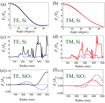
In the case of silicon, OPF is also achieved for TM polarization as shown in Fig. 2(d). In contrast with the TE configuration, the pulling effect here is not captured by the dipolar curve and is then not related to interference between electric and magnetic dipoles. Instead, it results from contributions of higher multipoles yielding an enhancement of scattering along the -axis bisecting the directions of incidence and which can only be understood within the full Mie theory as it takes place at larger radii.
As expected, the dipolar approximation fails to describe the behavior of the optical force on SiO2 microspheres in the size range shown in Figs. 2(e)-(f). Since its refractive index is lower than in the case of silicon, very small SiO2 spheres behave as induced electric dipoles with a negligible magnetic dipole contribution. As a consequence, the exact optical force is mostly positive in the range shown in 2(e)-(f) (except for a negligible pulling effect near for TE polarization). In short, OPF is not found in the case of very small SiO2 beads as the scattering angular distribution resembles the electric dipole (Rayleigh) distribution and hence does not favor the forward direction.
To circumvent this issue we put forward the strategy of doping the SiO2 spheres with gold spherical inclusions (radius ) in order to excite electric and magnetic dipoles simultaneously. We assume and then model this system as an effectively homogenous medium with the help of the extended Maxwell-Garnet theory Ruppin2000 ; Mallet2005 . The effective refractive index of the composite sphere is obtained from the effective relative permittivity and permeability:
| (24) |
| (25) |
where denotes the volume filling fraction. The dipolar Mie coefficients of the inclusions and are derived from the corresponding size parameter and from the value for the gold relative permittivity at Johnson1972 .
In Fig. 3, we plot the optical force as a function of sphere radius for TE (black) and TM (red) polarizations. We take as the half-angle between the two beams. The results for homogenous SiO2 spheres () are shown in 3(a), whereas the force on composite spheres with gold inclusions () are shown in 3(b). Measurable OPF on homogeneous SiO2 spheres can be obtained for relatively large radii in the case of TE polarization, while the force is always positive for TM. Such striking difference between the two cases shows that the relative phase between the scattered fields produced by each plane wave component strongly depends on the incident polarization. Thus, the condition for constructive interference near the forward direction can be controlled by the incident polarization.
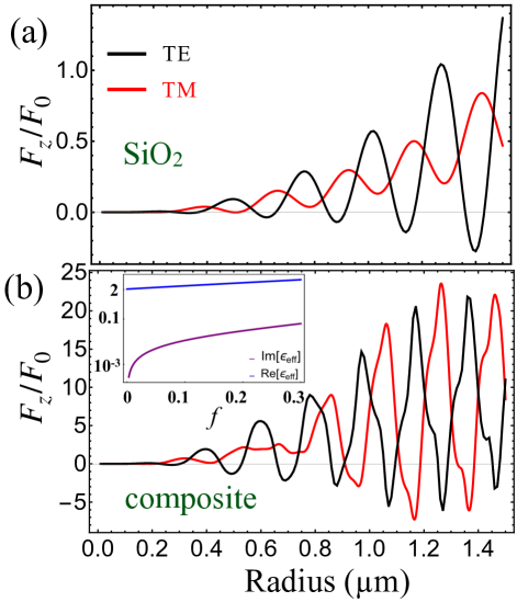
The scenario is drastically changed when one considers the SiO2 host sphere with gold inclusions, as shown in Fig. 3(b). Indeed, the presence of gold inclusions not only allows for OPF for both TE and TM polarizations, but also increases its magnitude by about one order of magnitude. At specific size ranges and depending on the polarization, the fields scattered by the inclusions interfere constructively (destructively) near the forward (backward) direction, then leading to a strong pulling effect. The resulting optical forces for TE and TM polarizations oscillate nearly out-of-phase as a function of the radius as shown in Fig. 3(b). Thus, the size intervals allowing for OPF using TE beams is approximately the complement of the intervals allowing for OPF using TM beams. Such feature indicates the possibility of a polarization-controlled particle sorting according to particle size.
Adding metallic inclusions also allows to extend the range of optical pulling towards smaller sizes. Indeed, the effective permittivity increases with the filling fraction as shown in the inset of fig. 3(b). Moreover, the inclusions also lead to an effective permeability slightly different from one according to Eq. (25). In line with the discussion of sec. 2, both effects enhance the magnetic dipole contribution, which is essential for achieving OPF on small particles.
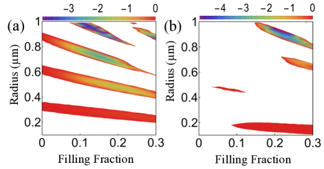
The occurrence of OPF on small particles is better visualized in the density plot of the OPF versus sphere radius and filling fraction shown in Fig. 4, for (a) TE and (b) TM polarizations. Colored areas indicate optical pulling forces whereas the regions corresponding to optical pushing forces are left blank for clarity. The overall disposition of the colored regions indicates that the conditions for OPF become more selective for bigger particles as a larger number of multipoles contribute to scattering. Indeed, in this case a fine tuning of the material parameters is required to achieve the simultaneous interferometric conditions involving all multipoles contributing to the scattering force component (II).
In the case of TE polarization, the colored areas appear as a pattern of stripes illustrating how the size intervals allowing for OPF depend on the filling fraction. Within a given stripe, the magnitude of the OPF is initially enhanced as increases from zero (homogenous case). Stripes corresponding to larger radii (upper part) are increasingly more inclined and tend to shrink as the filling fraction increases. Both features are related to light absorption by the microsphere. The inset of fig. 3(b) shows that increases sharply as a function of As the penetration depth decreases approaching the sphere diameter the fraction of absorbed light increases, which is clearly detrimental to the pulling effect. For very small spheres, absorption is still negligible and then the width of the lower stripes in Fig. 4(a) are approximately uniform. On the other hand, the stripes corresponding to larger radii are more affected by absorption as expected. They shrink and eventually disappear as and consequently increase. Also, the inclination of the stripes shows that the reduction of the penetration depth is compensated by a sharp decrease of the radii allowing for pulling so as to keep the ratio approximately unchanged.
The overall picture is similar in the case of TM polarization shown in Fig. 4(b). However, the pulling regions are more scarce, and very small filling fractions are excluded in this case.
IV Conclusion
We have developed a theoretical framework to calculate the optical pulling force on a microsphere illuminated by a superposition of plane waves. Due to the rotational symmetry of the scatterer, Mie scattering of plane waves propagating along arbitrary directions can be connected with the more standard case of axial propagation by employing Wigner rotation matrices and Debye potentials. We have derived an explicit result for the optical force as a partial-wave series when considering the example involving two linearly polarized plane waves. However, it is straightforward to extend our approach to multiple plane waves with arbitrary polarizations. The case of circular polarization might be particularly interesting given its possible application on enantioselective manipulation of chiral particles.
Our results show that TE-polarized waves can pull low and high refractive-index particles alike. In the former case, the technique is limited to larger sizes, involving higher multipoles beyond the electric and magnetic dipoles. On the other hand, TM-polarized waves allow for OPF only on high-refractive index particles. We have shown that the use of a metamaterial platform not only leads to an order of magnitude increase in the pulling force, but also allows to pull smaller particles, thus extending the technique into the dipolar regime. As a specific example, we have considered a low-index dielectric sphere doped with plasmonic inclusions. The strong enhancement in the pulling force is achieved for small values of the filling fraction, to avoid the detrimental effect of absorption. In this configuration, the size ranges which allow for pulling for each orthogonal polarization are approximately complementary. Such feature could be applied to implement a polarization-controled particle sorting using OPF.
Funding. National Council for Scientific and Technological Development (CNPq–Brazil), Coordination for the Improvement of Higher Education Personnel (CAPES–Brazil), the National Institute of Science and Technology Complex Fluids (INCT-FCx), and the Research Foundations of the States of Minas Gerais (FAPEMIG), Rio de Janeiro (FAPERJ) and São Paulo (FAPESP).
Acknowledgment. We thank Felipe S. S. da Rosa for inspiring discussions.
References
- (1) A. Ashkin, Acceleration and trapping of particles by radiation pressure, Phys. Rev. Lett. 24, 156 (1970).
- (2) A. Ashkin, J. M. Dziedzic, J. E. Bjorkholm, and S. Chu, Observation of a single-beam gradient force optical trap for dielectric particles, Opt. Lett. 11, 288 (1986).
- (3) A. Ashkin, Optical trapping and manipulation of neutral particles using lasers: A reprint volume with commentaries (World Scientific, Singapore, 2006).
- (4) J. Gieseler, J. R. Gomez-Solano, et al., Optical Tweezers: A Comprehensive Tutorial from Calibration to Applications, arXiv:2004.05246 (2020).
- (5) M. E. J. Friese, T. A. Nieminen, N. R. Heckenberg, and H. Rubinsztein-Dunlop, Optical alignment and spinning of laser-trapped microscopic particles, Nature 394, 348 (1998).
- (6) D. G. Grier, A revolution in optical manipulation, Nature 424, 810 (2003).
- (7) J. Lin and Y. Q. Li, Optical trapping and rotation of airborne absorbing particles with a single focused laser beam, Appl. Phys. Lett. 104, 101909 (2014).
- (8) K. Diniz, R. S. Dutra, L. B. Pires, N. B. Viana, H. M. Nussenzveig, and P. A. Maia Neto, Negative optical torque on a microsphere in optical tweezers, Opt. Exp. 27, 5905 (2019).
- (9) R. Ali, F. A. Pinheiro, F. S. S. Rosa, R. S. Dutra, P. A. Maia Neto, Enantioselective manipulation of chiral nanoparticles using optical tweezers, Nanoscale 12, 5031 (2020).
- (10) F. M. Fazal and S. M. Block, Optical tweezers study life under tension, Nat. Photon. 5, 318 (2011).
- (11) O. M. Maragò, P. H. Jones, P. G. Gucciardi, G. Volpe and A C. Ferrari, Optical trapping and manipulation of nanostructures, Nat. Nanotechnol, 8, 807 (2013).
- (12) O. Brzobohaty, M. Siler, J. Trojek, L. Chvatal, V. Karasek, A. Patak, Z. Pokorna, F. Mika, and P. Zemanek, Three-dimensional optical trapping of a plasmonic nanoparticle using low numerical aperture optical tweezers, Sci. Rep. 5, 8106 (2015).
- (13) P. Polimeno, A. Magazzù, et al., Optical tweezers and their applications, Journal of Quantitative Spectroscopy and Radiative Transfer 218, 131 (2018)
- (14) S. H. Lee, Y. Roichman, and D. G. Grier, Optical solenoid beams, Opt. Exp. 18, 6988 (2010).
- (15) J. Chen, J. Ng, Z. F. Lin, and C. T. Chan, Optical pulling force, Nat. Photonics 5, 531 (2011).
- (16) X. Li, J. Chen, Z. Lin, J. Ng. Optical pulling at macroscopic distances, Sci. Adv. 5, 7814 (2019).
- (17) V. Shvedov, A. R. Davoyan, N. Engheta and W. Krolikowski, A long-range polarization-controlled optical tractor beam, Nat. Photonics 8, 846 (2014).
- (18) H. Chen, S. Liu, Jian Zi, and Z. Lin, Fano resonance-induced negative optical scattering force on plasmonic nanoparticles, ACS Nano, 9, 1926 (2015).
- (19) T. Zhu et al, Self-induced backaction optical pulling force, Phs. Rev. Lett. 120, 123901 (2018).
- (20) R. W. Bowman, and M. J. Padgett, Optical trapping and binding, Rep. Prog. Phys. 76, 026401 (2013).
- (21) M. Mazilu and K. Dholakia, Resonance enhanced optical manipulation: the push and pull of light, Proc. SPIE 8458, 845809 (2012).
- (22) O. Brzobohaty, V. Karasek, M. Siler, L. Chvatal, T. Cizmar and P. Zemanek, Experimental demonstration of optical transport, sorting and self-arrangement using a ‘tractor beam’ Nat. Photonics 7, 123 (2013).
- (23) G. S. Wiederhecker, L. Chen, A. Gondarenko and M. Lipson, Controlling photonic structures using optical forces, Nature 462, 633 (2009).
- (24) A. Canaguier-Durand, J. A. Hutchison, C. Genet, and T. W. Ebbesen, Mechanical separation of chiral dipoles by chiral light, New J. Phys. 15, 123037 (2013).
- (25) K. Ding, J. Ng, L. Zhou, and C. T. Chan, Realization of optical pulling forces using chirality, Phys. Rev. A 89, 063825 (2014).
- (26) D. S. Bradshaw and D. L. Andrews, Chiral discrimination in optical trapping and manipulation, New J. Phys. 16, 103021 (2014).
- (27) S. B. Wang and C.T. Chan, Lateral optical force on chiral particles near a surface, Nat. Commun. 5, 3307 (2014).
- (28) A. Hayat, J. B. Mueller, and F. Capasso, Lateral chirality-sorting optical forces, Proc. Natl. Acad. Sci. U.S.A. 112, 13190 (2015).
- (29) M. Kamandi et. al, Enantiospecific detection of chiral nanosamples using photoinduced force, Phys. Rev. App. 8, 064010 (2017).
- (30) W. Ding, T. Zhu, Lei M. Zhou, and C. W. Qiub, Photonic tractor beams: a review, Adv. Photonics, 2, 024001 (2019).
- (31) F. G. Mitri, R. X . Li, R. P. Yang, L. X. Guo, C. Y. Ding, Optical pulling force on a magneto-dielectric Rayleigh sphere in Bessel tractor polarized beams, Journal of Quantitative Spectroscopy and Radiative Transfer, 184, 360 (2016).
- (32) I. V. Krasnov, Bichromatic optical tractor beam for resonant atoms, Phys. Lett. A 376 2743 (2012).
- (33) H. Liu, M. PanmaiI, Y. Peng, and S. Lan, Optical pulling and pushing forces exerted on silicon nanospheres with strong coherent interaction between electric and magnetic resonances, Opt. Exp. 11 , 12357 (2017).
- (34) E. Mobini, A. Rahimzadegan, C. Rockstuhl, and R. Alaee, Theory of optical forces on small particles by multiple plane waves, Journal of Applied Physics 124, 173102 (2018).
- (35) X. Bian, D. L. Gao, and L. Gao, Tailoring optical pulling force on gain coated nanoparticles with nonlocal effective medium theory, Opt. Exp. 25, 24566 (2017).
- (36) Rasoul Alaee et al. Optical Pulling and Pushing Forces in Bilayer PT-Symmetric Structures, Phy. Rev. App. 9, 014007 (2018).
- (37) S. Sukhov and A. Dogariu, Negative nonconservative forces: optical tractor beams for arbitrary objects, Phys. Rev. Lett. 107, 203602 (2011).
- (38) N. O. Länk, P. Johansson, and M Käll, Directional scattering and multipolar contributions to optical forces on silicon nanoparticles in focused laser beams, Opt. Exp. 26, 29074 (2018).
- (39) R. Ali, F. A. Pinheiro, F. S. S. Rosa, R. S. Dutra, P. A. Maia Neto, Optimizing optical tweezing with directional scattering in composite microspheres, Phys. Rev. A 98 , 053804 (2018).
- (40) R. Ali, Revisit of generalized Kerker’s conditions using composite metamaterials, J. Opt. in press https://doi.org/10.1088/2040-8986/ab9d14.
- (41) C. J. Bouwkamp and H. B. G. Casimir, On multipole expansions in the theory of electromagnetic radiation, Physica 20, 539 (1954).
- (42) P. A. Bobbert, and J. Vliger, Light scattering by a sphere on a substrate, Physica 137A, 209 (1986).
- (43) NIST Digital Library of Mathematical Functions. http://dlmf.nist.gov/25.12, Release 1.0.16 of 2017-09-18. F. W. J. Olver, A. B. Olde Daalhuis, D. W. Lozier, B. I. Schneider, R. F. Boisvert, C. W. Clark, B. R. Miller, and B. V. Saunders, eds.
- (44) A. R. Edmonds, Angular Momentum in Quantum Mechanics (Princeton University Press, Princeton, 1957).
- (45) C. F. Bohren and D. R. Huffman, Absorption and scattering of light by small particles (Wiley, New York, 1983).
- (46) R. Ruppin, Evaluation of extended Maxwell-Garnett theories, Opt. Commun. 182, 273 (2000).
- (47) P. Mallet, C. A. Guerin and A. Sentenac, Maxwell-Garnett mixing rule in the presence of multiple scattering: derivation and accuracy, Phy. Rev. B 72, 014205 (2005).
- (48) P. B. Johnson and R. W. Christy. Optical constants of the noble metals, Phys. Rev. B 6, 4370 (1972).