A stacked prism lens concept for next generation hard X-ray telescopes
Abstract
Effective collecting area, angular resolution, field of view and energy response are fundamental attributes of X-ray telescopes. The performance of state-of-the-art telescopes is currently restricted by Wolter optics, especially for hard X-rays. In this paper, we report the development of a new approach - the Stacked Prism Lens, which is lightweight, modular and has the potential for a significant improvement in effective area, while retaining high angular resolution. The proposed optics is built by stacking discs embedded with prismatic rings, created with photoresist by focused UV lithography. We demonstrate the SPL approach using a prototype lens which was manufactured and characterized at a synchrotron radiation facility. The design of a potential satellite-borne X-ray telescope is outlined and the performance is compared to contemporary missions.
KTH Royal Institute of Technology, Department of Physics, 106 91, Stockholm, Sweden.2 The Oskar Klein Centre for Cosmoparticle Physics, AlbaNova University Centre, 106 91, Stockholm, Sweden. *e-mail: wujun.mi@mi.physics.kth.se
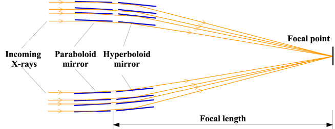
Since the first orbiting X-ray telescope, the Einstein Observatory, was launched in 1978, focusing X-ray telescopes (XRTs) have provided new knowledge on the universe by observing remote objects in the X-ray spectrum[karouzos2017x, gorenstein2010focusing]. The performance of XRTs is mainly determined by the optics. State-of-the-art focusing XRTs rely on Wolter optics, for which X-rays that are nearly parallel to the nested mirrors are collected by total external reflection. This has been successfully employed in several telescopes (e.g. Chandra[weisskopf2000chandra], XMM-Newton[jansen2001xmm], Swift[gehrels2004swift] and the planned ATHENA mission[nandra2013hot]), for X-rays in the energy range of 0.1 to 10 keV with high values of efficiency, angular resolution and sensitivity. However, for X-ray energies higher than 10 keV, using the same technique compromises spatial resolution and efficiency since the grazing angle quickly decreases with energy, making the focal length of the system impractically long and the field of view (FoV) very small. Moreover, the efficiency of the mirrors decreases, and nesting becomes more difficult. To mitigate this issue, it is possible to use multi-layered coatings and Bragg-reflection from depth-graded multi-layers to increase the grazing angle in the hard X-ray energy range[koglin2009nustar, koglin2003development]. Current hard X-ray focusing telescopes such as NuSTAR[harrison2013nuclear1] and Astro-H[takahashi2012astro, awaki2017hitomi] are designed this way. Although this provides a significant improvement in performance for hard X-rays, the long focal length is challenging when designing missions, and the small effective collecting area and narrow FoV limits the scientific return from missions. In addition, the angular resolution is severely influenced by figure error, surface roughness and assembly precision[gorenstein2010focusing].
At present, refractive[Cederstroem2000, snigirev1996compound] and diffractive transmissive X-ray optics[chang2014ultra] have been used in a wide range of applications[sakdinawat2010nanoscale, chao2005soft, di1999high], such as biology[schneider2010three], chemistry[shapiro2014chemical] and lithography[leontowich2011zone, larciprete2002direct]. Several novel zone plates[chang2014ultra], such as multilayer zone plates[keskinbora2014multilayer, kang2008focusing, huang201311, kang2006nanometer], interlaced zone plates[mohacsi2017interlaced] and stacked zone plates[maser2002near], as well as refractive optics, such as commercially available compound refractive X-ray lenses[snigirev1996compound], have been developed for hard X-ray imaging. The excellent resolution of these lenses makes them very competitive, but their limited apertures, low efficiency and fabrication difficulties remain obstacles for any direct application in hard X-ray astronomy. Various XRT concepts based on diffractive and refractive optics[skinner2001diffractive, refId0, skinner2008milli, braig2010fresnel, braig2010multiband] have been proposed and investigated for many years, with milli-arcsecond resolution expected. However, nearly all of them work only for X-ray energies <11 keV and the focal length, up to thousands of kilometers between optics and detector spacecrafts, makes it impractical to turn these ideas into mature systems.
In this paper, we demonstrate a new concept in point-focusing X-ray optics, the Stacked Prism Lens (SPL). These lenses are based on SU-8 polymer photoresist and fabricated by focused UV lithography[mi2016fabrication] using a conventional mask aligner, which is easily adopted for mass production. The performance as compared to current X-ray optics is considerably improved and most importantly, our new method allows arrays of X-ray lenses to form a scaleable modular assembly which has the potential to remove today’s hard limits on effective area and FoV for hard X-ray focusing telescopes, while still maintaining an excellent angular resolution.
Results
Pricinple of Stacked Prism Lenses.
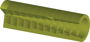
Fig. 1 shows the schematics of the proposed Stacked Prism Lens. Each individual lens (Fig. 1) is built by stacking discs embedded with a variable number of identical prismatic rings (Fig. 1).
[figure]style=plain,subcapbesideposition=top
[labelformat=simple]
 \sidesubfloat[]

[]
 \sidesubfloat[]
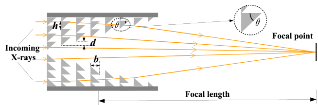
The lens can be described as a rotationally symmetric version of prism-array lenses[cederstrom2005generalized] or Clessidra lenses[jark2004focusing]. The basic scheme of the Stacked Prism Lens (Fig. 1) is obtained by removing chunks of material corresponding to a multiple of phase shift in a multi-prism lens[Cederstroem2000], chosen to functionally approximate the shape of parabolic lens stepwise with linear segments[nillius2011large]. Unlike Wolter type I optics (Fig. 1), these lenses focus incident radiation into a spot via both refraction (Fig. 1) and diffraction[jark2008role]. The focal length of each Stacked Prism Lens is
| (1) |
where is the columnar displacement, is the prism height and is the prism base. is the angle subtended by the prism height, i.e. . is the deviation from unity of the real part of the refractive index, . Similarly to the compound refractive lens, a shorter focal length can be obtained by stacking a series of Stacked Prism Lenses, i.e. .
Fabrication of Stacked Prism Lenses.
The main fabrication process steps for Stacked Prism Lenses are illustrated in Fig. 2.
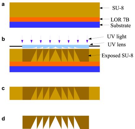
The discs used to build up Stacked Prism Lenses are fabricated using focused UV lithography[mi2016fabrication], for which a UV lens is employed to shape the UV beam and pattern the photoresist, instead of the binary photomask used in conventional UV lithography. The UV lens is fabricated with grayscale e-beam lithography[mi2014efficient]. The negative photoresist, SU-8 2100, is used as structural material for the discs. A v-groove with low surface roughness is utilized to align fabricated discs and assemble the Stacked Prism Lens.
[]
\sidesubfloat[]
 \sidesubfloat[]
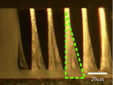
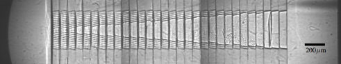
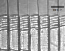
show transmission images of a completed Stacked Prism Lens, which were taken by illuminating the lens from the side using an X-ray beam. The imaged lens comprises 30 discs with 1 mm diameter, embedded with different numbers of circular prismatic rings. The prism base ; the prism height ; and the column displacement , in comparison to the design values with , and . The geometric aperture of the lens is 420 . Fig. 3 shows a cross-section image of a fabricated disc under an optical microscope. As can be expected in the first prototypes, there are some imperfections in the fabricated Stacked Prism Lens, such as structural collapse (Fig. 3) and obtuse prism tips (Fig. 3), which will degrade lens performance.
Optical properties of Stacked Prism Lenses.
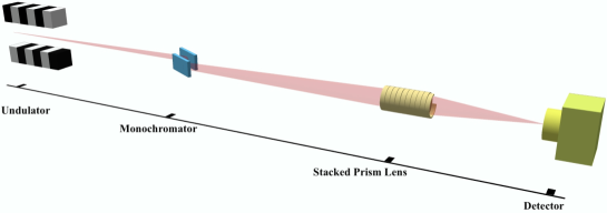
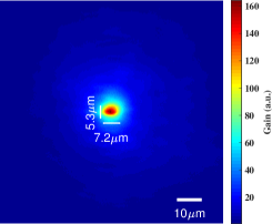
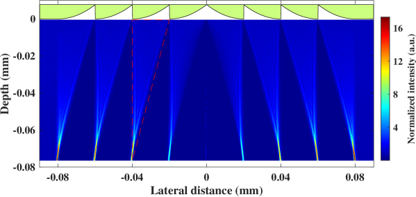
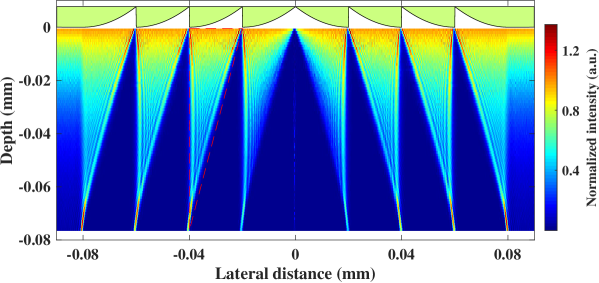
The optical performance of the fabricated Stacked Prism Lens was characterized at beamline B16 of the Diamond Light Source (Oxford, UK), with the experiment setup outlined in Fig. 4. This beamline has a source with an effective spot size of 126 56 (FWHM). The fabricated Stacked Prism Lenses were illuminated with a monochromatic beam as the lens-to-beam rotation angle, titled angle and lens-to-detector separation, and the beam energy were scanned iteratively to find the configuration for the best performance. A PCO.4000 camera with a pixel size of 9 , a objective and a point spread function (PSF) with an FWHM of 2.3 was used to record the intensity distribution. In addition, a ray-tracing model was used to simulate the optical performance of Stacked Prism Lenses with both ideal and manufactured prism profiles assuming the same configurations as in the experiment. The simulation was written specifically for this purpose and implemented in a combination of Matlab and C++. To compare with the measurements the simulated intensity is convolved with the detector’s point-spread function.
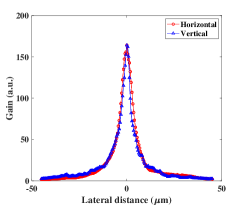
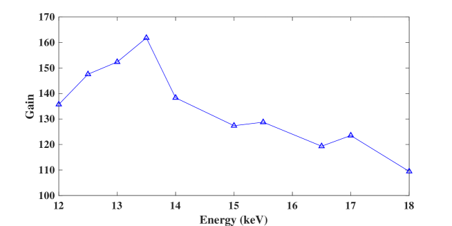
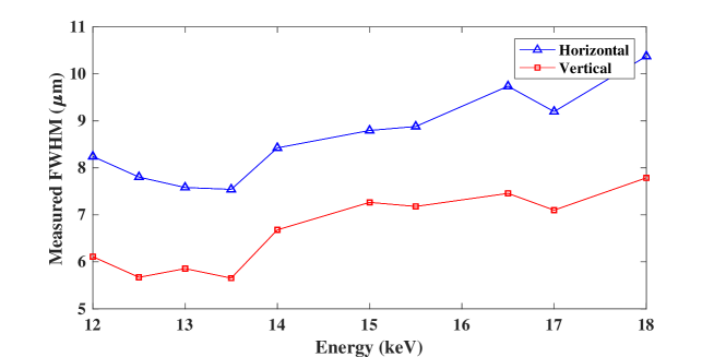
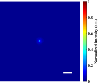
The minimum spot size and maximum intensity gain were obtained at an energy of 13.5 keV (Supplementary Fig. 1), for a lens-to-detector separation of 705 mm, compared to 717 mm for both simulation and numerical calculation results. The gain distribution in the focal plane (Fig. 4) is calculated by comparing intensity distributions with and without a lens. Just like the X-ray source, the measured focal spot is elliptical with FWHM of 7.2 and 5.3 in the horizontal and vertical direction, respectively, and the maximal intensity gain is around 164. The measured FWHM is around 50% wider and the gain is less than one third of the simulated values. Deconvolving with X-ray spot size and the detector’s PSF, the real spot size (FWHM) is estimated to be around 3 , which is far from the numerically calculated diffraction-limited resolution of 152 nm. These differences can be attributed to the deficiencies (such as prism profile, alignment, and so on) between the simulation model and the fabricated lens.
[]
 \sidesubfloat[]
 \sidesubfloat[]
\sidesubfloat[]
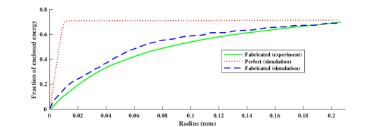
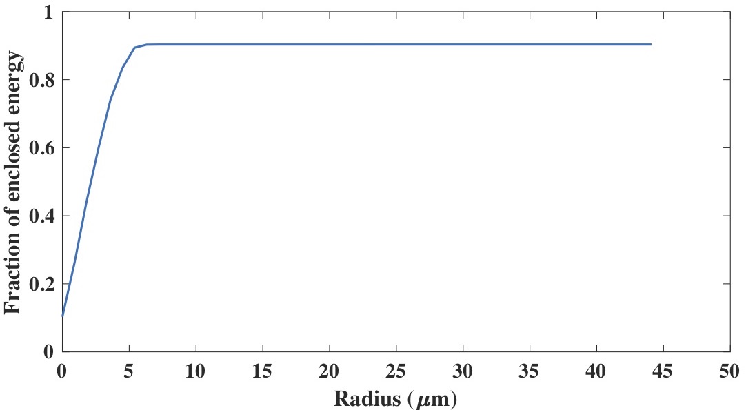
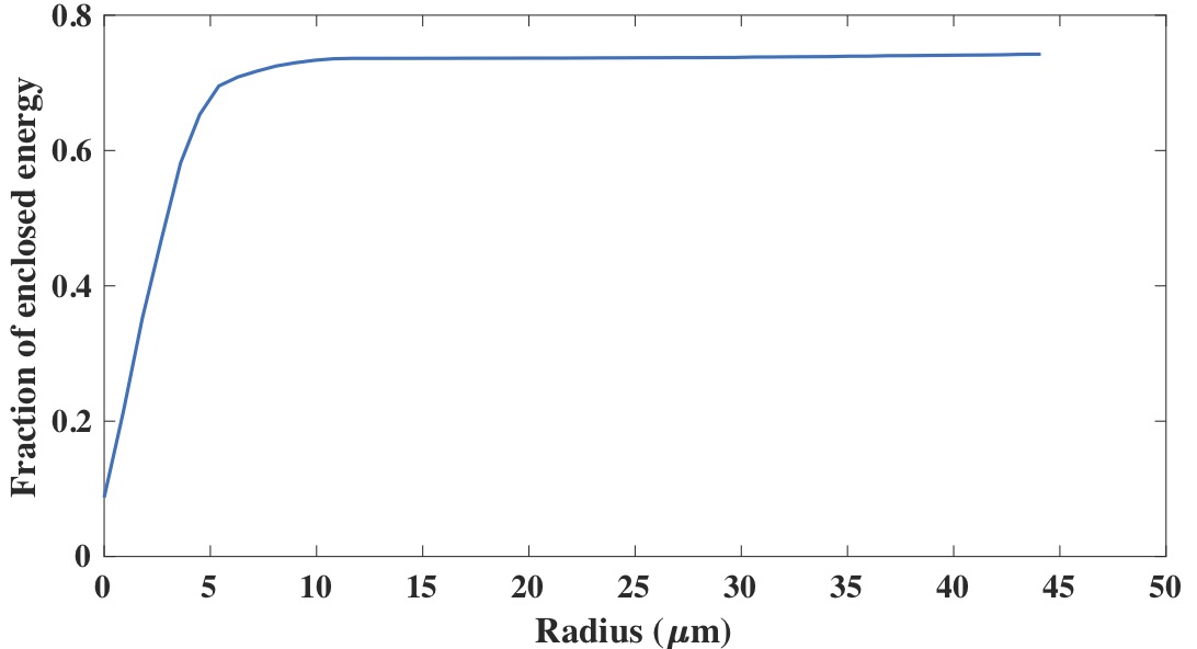
The focal properties for Stacked Prism Lens are analysed in more detail in Fig. 4, which shows the fraction of enclosed energy as a function of radius, obtained by integrating the intensity inside a certain position from the optical axis and comparing to the total illuminated flux. Besides resolution, efficiency is also an important property for hard X-ray optics. For the fabricated lens, the measured total efficiency is about 70%, compared to 69% and 71.5% for the simulation results of the fabricated and ideal lens, respectively. This means that the effective aperture is about of the geometric aperture, 352 . (For an ideal beryllium compound refractive lens with the same focal length and geometric aperture, the total efficiency is only 15%.) However, the energy inside the central peak (with a radius of around 10 ) is about 10%, which means only about 15% of the transmitted flux is refracted properly into the central peak. 50% of the transmitted flux is distributed over an area with a radius of around 43 , compared to around 35 and 5 for the simulation results of fabricated and ideal lenses, respectively.
The optical properties of the tested Stacked Prism Lens are slightly worse than the simulation result for the manufactured prism profile, but are not compatible with the simulation for an ideal prism profile. According to the simulations, the performance degradation is mainly due to profile aberration and alignment error, both arising from the equipment which is currently available in our lab. In the future, we will improve the fabrication processes by reducing the UV wavelength for lithography to avoid overexposure of tips (Supplementary Fig. 2) and using an accurate alignment machine when assembling. We expect that this will allow fabricated lenses to reach the theoretical performance values.
Hard X-ray telescope concept based on Stacked Prism Lens array.
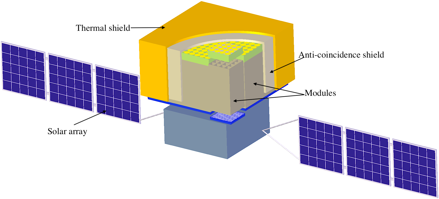
The basic concept for a hard X-ray focusing telescope based on the Stacked Prism Lens array is shown in Fig. 5,
[]
 \sidesubfloat[]
 \sidesubfloat[]
 \sidesubfloat[]
 \sidesubfloat[]
 \sidesubfloat[]
 \sidesubfloat[]

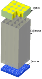
for which the instrumental part is built by an array of modules in a parallel arrangement (Fig. 5). Each module (Fig. 5) has its own optics plane and detector plane, supported by a multi-grid array collimator. Each grid element works as a miniature hard X-ray focusing telescope, consisting of a corresponding Stacked Prism Lens, a detector unit and a collimator aperture.
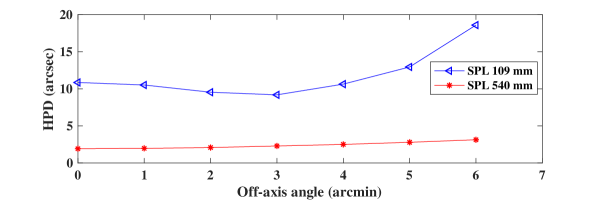
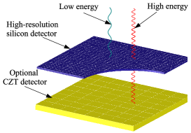
As is illustrated above, the optics plane consists of a Stacked Prism Lens array, manufactured by focused UV lithography using SU-8. The spatial resolution in half power diameter (HPD, defined as the diameter of the region that encompasses 50% of the focused flux) is around 4 at the optimum energy (Supplementary Fig. 3). The collimator comprises Tungsten or Molybdenum perforated with thousands of precisely aligned holes. The wall stops scattered stray X-rays and prevents crosstalk between adjacent grids (Fig. 5). We propose a 1 mm thick active pixel Silicon sensor with 2 spatial resolution[fossum1997cmos] and a partly event driven read-out, for a target power consumption of less than 1 . An alternative sensor design is a backlit CCD[soltau2000fabrication]. We do not expect the sensor to limit the performance of the telescope. A second sensor layer (Fig. 5) of 3 mm CZT would extend the upper energy limit to 200 keV, with coarser spatial resolution.
Compared with grazing incidence optics, a telescope based on a Stacked Prism Lens array has many advantages (Table 1).
| Parameters | NuSTAR | HXT(ASTRO-H) | XRT based on SPLs | XRT based on SPLs | ||||||||||||
|---|---|---|---|---|---|---|---|---|---|---|---|---|---|---|---|---|
| Optics | Wolter-I | Wolter-I |
|
|
||||||||||||
| Resolution HPD | 60′′ | 110′′ |
|
|
||||||||||||
| Resolution FWHM | 18′′ | 0.4′′ | 0.1′′@13.5 keV | 0.04′′@13.5 keV | ||||||||||||
| FoV | 12.5′ | 9′ | 9.8′ | 6.4′ | ||||||||||||
|
900 | 1 200 | 7.2 @13.5 keV | 8.5 @13.5 keV | ||||||||||||
| Energy range (keV) | 3-78.4 | 5-80 | 5-100 | 5-100 | ||||||||||||
| Focal length (m) | 10.15 | 12 | 0.109 | 0.54 | ||||||||||||
|
|
|
|
|||||||||||||
| Detector |
|
CZT | Si/CZT | Si/CZT | ||||||||||||
|
|
940 | 223 | 187 |
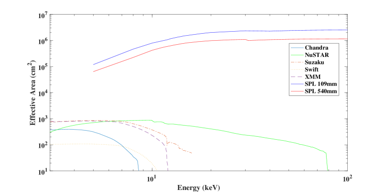
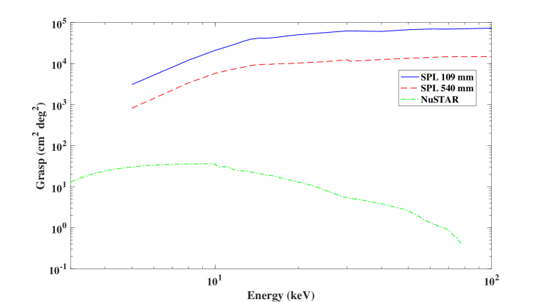
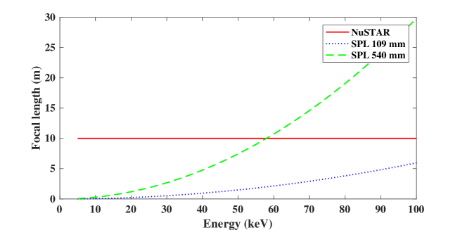
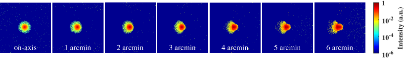
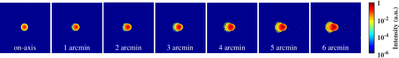
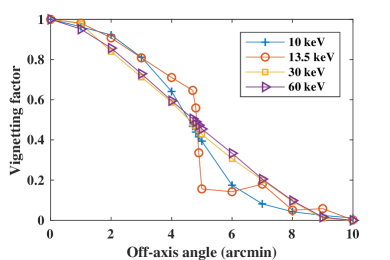
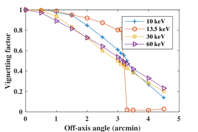
One advantage is higher angular resolution. The simulation suggests that for Stacked Prism Lenses with an ideal prism geometry, angular resolution better than 5′′ (HPD) and 0.1′′ (FWHM) can be achieved, a significant improvement compared to NuSTAR (Supplementary Fig. 4) and HXT(ASTRO-H). The PSF distorts as the off-axis angle increases, but the HPD remains approximately constant inside the FoV defined by the collimator (Supplementary Fig. 5). The use of linear prisms in the SPL results in the HPD significantly exceeding the FWHM (see discussion in Methods). The Stacked Prism Lens approach allows a modular hard X-ray focusing telescope to be designed. A major advantage of this approach is that the short focal length (e.g. 0.5 m, compared to 10 m for NuSTAR) means that a compact and lightweight (200 kg/m2) telescope is possible. There are many practical issues to resolve before realising the full scaleable potential of this approach. One such issue is the alignment and calibration of individual telescope assemblies within a module. We foresee that automated precision micro-fabrication techniques can be exploited here. When the full potential of the modular design is exploited, the resulting effective area and grasp (product of on-axis effective collecting area and effective FoV) stands to be significantly larger than offered by current missions (Supplementary Fig. 6 and Fig. 7).
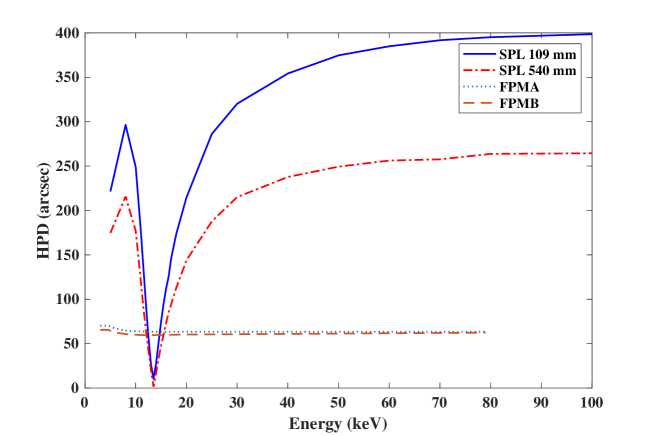
As a variant of the parabolic refractive lens, a Stacked Prism Lens is intrinsically chromatic since the focal length is proportional to (Supplementary Fig. 8), which means that high resolution is only achieved for X-rays with limited bandwidth around an optimum energy (Fig. 5). For X-rays with lower and higher energies (Fig. 5 and 5), the angular resolution is degraded (Supplementary Fig. 4). Thus, it appears very difficult to match the performance of a Wolter type XRT across a broad X-ray spectrum. This problem can be partially addressed by combining Stacked Prism Lenses designed for different optimum energies or by combining a diffractive phase Fresnel lens and a Stacking Prism Lens to correct the chromatic aberration [skinner2004design, wang2003achromatic].
Discussion
In this paper, we have demonstrated the feasibility and characterization of the Stacked Prism Lens for hard X-rays and investigate a practical application. By approximating the parabolic lens but partially removing the absorption materials, we can construct novel X-ray optics with point focusing and high resolution, high efficiency and large effective aperture size. The manufactured Stacked Prism Lenses comprise SU-8 discs embedded with variable numbers of prismatic rings. These discs were patterned using focused UV lithography, a technique which is simple, inexpensive, and suitable for mass production.
Through experiment, we show that the manufactured Stacked Prism Lens is able to match their expected performance on resolution, efficiency, and effective aperture. Although there were fabrication imperfections, we were still able to attain a focal spot of 5 7 (FWHM), total transmission of 70%, and a large effective aperture of 352 , for a geometric aperture of 420 at an optimum energy of 13.5 keV. Simulation studies suggest that significantly improved results can be achieved for ideal prisms with improved alignment between the prismatic ring elements. The fabrication process needs to be improved to achieve this.
A hard X-ray focusing telescope concept is introduced using an array of Stacked Prism Lenses and a two-layer detector arrangement. Compared with today’s state-of-the-art hard X-ray telescopes, it is more compact (due to the short focal length) and lightweight (with high efficiency and light polymer lenses leading to small mass per effective collecting area) with the modular approach having the potential to provide a significant increase both in effective area and grasp. Depending on the application the angular resolution can be improved around an optimum design energy over current Wolter optics, while sacrificing resolution towards higher energies. Despite drawbacks in terms of bandwidth, there is excellent scientific potential for a hard X-ray telescope based on Stacked Prism Lenses in hard X-ray astronomy as well as numerous applications in other areas, such as condenser lenses in X-ray microscopes[marschall2014x], optics for HyperSPECT system[tibbelin2012simulation], and so on.
Acknowledgements
We acknowledge the Diamond Light Source for provision of synchrotron radiation facilities and express our thanks to Oliver Fox and Kawal Sawhney for assistance in applying and using beamline B16. We thank Cheng Xu and Staffan Karlsson for taking part in the experiment at the Diamond Light Source, Christer Svensson for the detector design and power calculation and Le Mi for X-ray telescope concept drawing. W.M and M.D. acknowledge funding from Stiftelsen Olle Engkvist Byggm stare. M.P. acknowledges funding received from the Swedish Research Council (grant number 2016-04929).
Author contributions
W.M. performed the design, fabrication, test experiments and simulation of the Stacked Prism Lens, analyzed the experiment data and space application, and prepared the paper. P.N. contributed to the design of Stacked Prism Lens and the development of the simulation program, performed the X-ray experiments, and discussed the experiment results. M.P. discussed and developed the space application of Stacked Prism Lenses and assisted with the writing of the manuscript. M.D. managed the project, proposed applications for space and other areas, and together with the co-authors coordinated the writing of the manuscript.
Author information
Reprints and permissions information is available at www.nature.com/reprints. The authors declare that they have no competing financial interests. Correspondence and requests for materials should be addressed to Wujun Mi (email: wujunmi@mi.physics.kth.se).
Methods
Lens investigated.
Stacked Prism Lenses use prisms or curved prisms to focus X-rays. Each prism has a height, h, and a base, , where is a positive integer to ensure the phase continuity, is the wavelength, and is the refractive index decrement from unity for an X-ray of wavelength . The beam deflection angle when passing a single prism is[cederstrom2002multi]
| (2) |
The rays, hitting the lens at a distance from optical axis, will be deflected through an angle
| (3) |
where the square brackets denote rounding to the nearest integer. The rays near the edges pass through more prisms than the rays in the centre, thereby creating a focusing effect. However, the rays hitting the lens within the same columnar displacement, will be refracted with the same angle, i.e. perfect focusing is not possible with these linear prisms. A promising solution to this issue is to use prisms with a curved profile[jark2004focusing]. For the Stacked Prism Lens, is a free parameter and is not limited by the prism height. Smaller means a closer approximation to an ideal Fresnel pattern and thus smaller focal spot, but requires more accurate alignment and complicated fabrication. Similarly with the compound refractive lens, shorter focal length can be obtained by stacking several identical Stacked Prism Lenses, which results in
| (4) |
Here, is the number of Stacked Prism Lenses. Since , the focal length or . The projected material thickness of Stacked Prism Lenses at a distance to the optical axis can be expressed by
| (5) |
This shows that the thickness grows linearly with the distance to the optical axis. Taking geometric scattering[nillius2011large] into consideration results in the transmission function
| (6) |
where is the attenuation coefficient in the lens material, including Compton scattering and photo-electric absorption. The effective aperture, defined as the diameter of aperture that would transmit an equal amount of power throughout the whole geometric aperture, is an important parameter for X-ray optics. For Stacked Prism Lenses, it can be expressed by[nillius2012geometric]
| (7) |
And the maximum aperture is computed as
| (8) |
The corresponding diffraction-limited resolution[lengeler1999imaging] is
| (9) |
Lithographic process for the UV lens.
The fabrication method for the UV lens is grayscale e-beam lithography[mi2014efficient, mi2016fabrication]. The e-beam resist SML 1000 was used as structural material. The substrate was ITO-coated glass, which is almost transparent for near ultraviolet light. Before applying the SML 1000, a 40 nm-thick gold layer was deposited underneath the UV lens to form solid disks. A 1350 -thick layer of SML 1000 was then spin coated, baked at 180 for 3 minutes and then patterned with a 25 keV Raith 150 e-beam lithography system. A proximity-effect-correction method based on multivariate adaptive regression splines (MARS) was employed to calculate the variable dose required for the desired UV lens profile. The patterned resist was developed in methyl isobutyl ketone (MIBK) for 20 seconds, rinsed in isopropyl alcohol (IPA) for 30 seconds, and then dried with flowing nitrogen.
Lithographic process for discs.
The stacked discs were fabricated by focused UV lithography with SU-8 2100 photoresist. The fabrication process started with a Si wafer of 550 thickness. After pretreating, LOR 7B and SU-8 2100 were spin-coated on the wafer with a thickness of 1 and 84 , respectively. The lift-off resist LOR 7B was utilized as a sacrificial layer to release the SU-8 structures from the Si wafer. After relaxation, the sample was baked on a levelled hotplate at 65 for 3 hours. After cooling to room temperature, it was exposed with a Karl Suss MJB3 mask aligner equipped with an i-line filter in hard contact with the UV lens for 50 seconds. After post-exposure baking for 2 hours at 65 , the sample was then pre-developed in SU-8 developer PGMEA (Propylene Glycol Monomethyl Ether Acetate) for 10 seconds with the help of ultrasonic vibration. The SU-8 structure was released from the Si wafer using MicropositTM MF-319 developer and subsequently developed again in PGMEA at -20 for 1 hour, rinsed in IPA for 30 seconds and then dried at room temperature.
Lens simulation.
The software used to simulate the lens is custom-built, based on ray tracing and designed specifically for Stacked Prism Lenses. The regular structure of the Stacked Prism Lens is exploited to speed up the calculations, by storing the prisms in a regular grid structure, where each grid cell contains a small subset of the prisms. The prisms’ shapes are represented as rotationally symmetric surfaces, i.e. each side of the prism forms a conical surface in 3D. Intersections between the photon path and the surfaces are computed analytically, thus avoiding the need to approximate curved surfaces with piece-wise linear polygon meshes, and instead obtaining full precision at this step. At each surface intersection, the refraction and reflection are computed according to Snell’s law. Thereby, the full path of a photon can be traced through the lens and the optical system. The transmitted photons are gathered at a detector layer, where they are binned according to their position on the detector and the amount of attenuation. The attenuation of a photon path is computed according to the distance traveled in each material. Both photo-electric absorption and Compton scattering are considered. The Compton scattered photons are assumed be absorbed by the high-aspect-ratio collimator. The software is implemented in a combination of Matlab and C++ and the framework has been used to compare measurements with simulations in several previous works[nillius2012geometric, nillius2011large].
Data Availability
The data that support the plots within this paper and other findings of this study are available from the corresponding author upon reasonable request.
References
References
- [1] Karouzos, M. X-ray astronomy: Black holes in the sky with Chandra. Nature Astronomy 1, 0046 (2017).
- [2] Gorenstein, P. Focusing X-ray optics for astronomy. X-Ray Opt. Instrum. 2010 (2010).
- [3] Weisskopf, M. C., Tananbaum, H. D., Van Speybroeck, L. P. & O’Dell, S. L. Chandra X-ray Observatory (CXO): Overview. In X-Ray Optics, Instruments, and Missions III, vol. 4012, 2–17 (International Society for Optics and Photonics, 2000).
- [4] Jansen, F. et al. XMM-Newton observatory-I. The spacecraft and operations. Astron. Astrophys. 365, L1–L6 (2001).
- [5] Gehrels, N. et al. The Swift Gamma-Ray Burst Mission. Astrophys. J 611, 1005 (2004).
- [6] Nandra, K. et al. The Hot and Energetic Universe: A White Paper presenting the science theme motivating the Athena+ mission. arXiv:1306.2307 (2013).
- [7] Koglin, J. E. et al. NuSTAR hard X-ray optics design and performance. In Optics for EUV, X-Ray, and Gamma-Ray Astronomy IV, vol. 7437, 74370C (International Society for Optics and Photonics, 2009).
- [8] Koglin, J. E. et al. Development and production of hard X-ray multilayer optics for HEFT. In X-Ray and Gamma-Ray Telescopes and Instruments for Astronomy, vol. 4851, 607–619 (International Society for Optics and Photonics, 2003).
- [9] Harrison, F. A. et al. The nuclear spectroscopic telescope array (NuSTAR) high-energy X-ray mission. Astrophys. J. 770, 103 (2013).
- [10] Takahashi, T. et al. The ASTRO-H X-ray Observatory. In Space Telescopes and Instrumentation 2012: Ultraviolet to Gamma Ray, vol. 8443, 84431Z (International Society for Optics and Photonics, 2012).
- [11] Awaki, H. et al. The Hitomi (ASTRO-H) hard x-ray telescope (HXT): current status of calibration. In Optics for EUV, X-Ray, and Gamma-Ray Astronomy VIII, vol. 10399, 103990R (International Society for Optics and Photonics, 2017).
- [12] Cederström, B., Cahn, R. N., Danielsson, M., Lundqvist, M. & Nygren, D. R. Focusing hard X-rays with old LPs. Nature 404, 951 (2000).
- [13] Snigirev, A., Kohn, V., Snigireva, I. & Lengeler, B. A compound refractive lens for focusing high-energy X-rays. Nature 384, 49 (1996).
- [14] Chang, C. & Sakdinawat, A. Ultra-high aspect ratio high-resolution nanofabrication for hard X-ray diffractive optics. Nat. Commun. 5, 4243 (2014).
- [15] Sakdinawat, A. & Attwood, D. Nanoscale X-ray imaging. Nat. Photonics 4, 840–848 (2010).
- [16] Chao, W., Harteneck, B. D., Liddle, J. A., Anderson, E. H. & Attwood, D. T. Soft X-ray microscopy at a spatial resolution better than 15 nm. Nature 435, 1210 (2005).
- [17] Di Fabrizio, E. et al. High-efficiency multilevel zone plates for keV X-rays. Nature 401, 895 (1999).
- [18] Schneider, G. et al. Three-dimensional cellular ultrastructure resolved by X-ray microscopy. Nat. Methods 7, 985 (2010).
- [19] Shapiro, D. A. et al. Chemical composition mapping with nanometre resolution by soft X-ray microscopy. Nat. Photonics 8, 765 (2014).
- [20] Leontowich, A. F. & Hitchcock, A. P. Zone plate focused soft X-ray lithography. Appl. Phys. A 103, 1–11 (2011).
- [21] Larciprete, R. et al. Direct writing of fluorescent patterns on LiF films by X-ray microprobe. Appl. Phys. Lett. 80, 3862–3864 (2002).
- [22] Keskinbora, K. et al. Multilayer Fresnel zone plates for high energy radiation resolve 21 nm features at 1.2 keV. Opt. Express 22, 18440–18453 (2014).
- [23] Kang, H. C. et al. Focusing of hard X-rays to 16 nanometers with a multilayer Laue lens. Appl. Phys. Lett. 92, 221114 (2008).
- [24] Huang, X. et al. 11 nm hard X-ray focus from a large-aperture multilayer Laue lens. Sci. Rep. 3, 3562 (2013).
- [25] Kang, H. et al. Nanometer linear focusing of hard X rays by a multilayer Laue lens. Phys. Rev. Lett. 96, 127401 (2006).
- [26] Mohacsi, I. et al. Interlaced zone plate optics for hard X-ray imaging in the 10 nm range. Sci. Rep. 7 (2017).
- [27] Maser, J. et al. Near-field stacking of zone plates for hard X-ray range. In Design and Microfabrication of Novel X-Ray Optics, vol. 4783, 74–82 (International Society for Optics and Photonics, 2002).
- [28] Skinner, G. Diffractive-refractive optics for high energy astronomy-I. Gamma-ray phase Fresnel lenses. Astron. Astrophys. 375, 691–700 (2001).
- [29] Skinner, G. K. Diffractive-refractive optics for high energy astronomy - II. Variations on the theme. Astron. Astrophys. 383, 352–359 (2002).
- [30] Skinner, G. et al. The milli-arc-second structure imager (MASSIM): a new concept for a high angular resolution x-ray telescope. In SPIE Astronomical Telescopes+ Instrumentation, 70110T–70110T (International Society for Optics and Photonics, 2008).
- [31] Braig, C. & Predehl, P. Fresnel lens arrays for X-ray imaging spectroscopy. In SPIE Astronomical Telescopes+ Instrumentation, 77322N–77322N (International Society for Optics and Photonics, 2010).
- [32] Braig, C. & Predehl, P. Multiband imaging with Fresnel X-ray telescopes. In Proc. SPIE, vol. 7732, 77322M (International Society for Optics and Photonics, 2010).
- [33] Mi, W., Karlsson, S., Holmberg, A., Danielsson, M. & Nillius, P. Fabrication of circular sawtooth gratings using focused UV lithography. J. Micromech. Microeng. 26, 035001 (2016).
- [34] Cederström, B., Ribbing, C. & Lundqvist, M. Generalized prism-array lenses for hard X-rays. J. Synchrotron Radiat. 12, 340–344 (2005).
- [35] Jark, W. et al. Focusing X-rays with simple arrays of prism-like structures. J. Synchrotron Radiat. 11, 248–253 (2004).
- [36] Nillius, P., Karlsson, S., Cederström, B., Fredenberg, E. & Danielsson, M. Large-aperture focusing of high-energy X rays with a rolled polyimide film. Opt. Lett. 36, 555–557 (2011).
- [37] Jark, W., Matteucci, M., Menk, R., Rigon, L. & De Caro, L. The role of spatial coherence, diffraction and refraction in the focusing of X-rays with prism arrays of the Clessidra type. In Proceedings of SPIE, the International Society for Optical Engineering, 70771X–1 (Society of Photo-Optical Instrumentation Engineers, 2008).
- [38] Mi, W. & Nillius, P. Efficient proximity effect correction method based on multivariate adaptive regression splines for grayscale e-beam lithography. J. Vac. Sci. Technol. B 32, 031602 (2014).
- [39] Fossum, E. R. Cmos image sensors: Electronic camera-on-a-chip. IEEE Trans. Electron 44, 1689–1698 (1997).
- [40] Soltau, H. et al. Fabrication, test and performance of very large X-ray CCDs designed for astrophysical applications. Nucl. Instr. Meth. Phys. Res. 439, 547–559 (2000).
- [41] Skinner, G. K. Design and imaging performance of achromatic diffractive–refractive X-ray and gamma-ray Fresnel lenses. Appl. Optics 43, 4845–4853 (2004).
- [42] Wang, Y., Yun, W. & Jacobsen, C. Achromatic Fresnel optics for wideband extreme-ultraviolet and X-ray imaging. Nature 424, 50 (2003).
- [43] Marschall, F. et al. X-ray full field microscopy at 30 kev. In J. Phys. Conf. Ser., vol. 499, 012007 (IOP Publishing, 2014).
- [44] Tibbelin, S., Nillius, P. & Danielsson, M. Simulation of HyperSPECT: a high-resolution small-animal system with in-line X-ray optics. Phys. Med. Biol. 57, 1617 (2012).
- [45] Cederström, B. A multi-prism lens for hard X-rays. Ph.D. thesis, KTH (2002).
- [46] Nillius, P. Geometric scattering in prism-array lenses for hard X-rays: Measurements, simulations and models. In AIP Conf. Proc., vol. 1437, 111–115 (AIP, 2012).
- [47] Lengeler, B. et al. Imaging by parabolic refractive lenses in the hard X-ray range. J. Synchrotron Radiat. 6, 1153–1167 (1999).
Supplementary Figures
[]
 \sidesubfloat[]
[]
 \sidesubfloat[]
[]
 \sidesubfloat[]
 \sidesubfloat[]
 \sidesubfloat[]
[]
[]
[]
 \sidesubfloat[]
[]