Ion beam sputtering of silicon: Energy distributions of sputtered and scattered ions
Abstract
The properties of sputtered and scattered ions are studied for ion beam sputtering of Si by bombardment with noble gas ions. The energy distributions in dependence on ion beam parameters (ion energy: 0.5 - 1 keV; ion species: Ne, Ar, Xe) and geometrical parameters (ion incidence angle, polar emission angle, scattering angle) are measured by means of energy-selective mass spectrometry. The presence of anisotropic effects due to direct sputtering and scattering is discussed and correlated with process parameters. The experimental results are compared to calculations based on a simple elastic binary collision model and to simulations using the Monte-Carlo code SDTrimSP. The influence of the contribution of implanted primary ions on energy distributions of sputtered and scattered particles is studied in simulations. It is found that a 10% variation of the target composition leads to detectable but small differences in the energy distributions of scattered ions. Comparison with previously reported data for other ion/target configurations confirms the presence of similar trends and anisotropic effects: the number of high-energy sputtered ions increases with increasing energy of incident ions and decreasing scattering angle. The effect of the ion/target mass ratio is additionally investigated. Small differences are observed with the change of the primary ion species: the closer the mass ratio to unity, the higher the average energy of sputtered ions. The presence of peaks, assigned to different mechanisms of direct scattering, strongly depends on the ion/target mass ratio.
I Introduction
Ion beam sputter deposition (IBSD) is one of the well-known physical vapor deposition (PVD) techniques. In comparison to other PVD techniques, such as magnetron sputtering or evaporation, IBSD offers the opportunity to tailor the properties of film-forming particles, and, therefore, film properties by varying the parameters of ion beam and sputtering geometry over a wide range Behrisch and Eckstein (2007). In the IBSD system, the generation of energetic ions (ion beam source), formation of secondary particle fluxes (sputtered and scattered ones at the target), and the film growth area are locally separated. Change of ion beam parameters and sputtering geometry results in different angular and energy distributions of sputtered target and scattered primary particles. The working pressure is typically less than Pa, so the mutual interaction within the secondary particle fluxes is much weaker than in magnetron sputtering or evaporation.
Although IBSD has been used for decades, its full capabilities have not been studied systematically until recently. Typically, a beam of primary ions with energies up to 2 keV is used. Several groups performed angularly resolved measurements of energy/velocity distributions of sputtered atoms Goehlich and Döbele (1996); Franke et al. (1997); Goehlich, Niemöller, and Döbele (1997, 1999); Goehlich, Gillmann, and Döbele (2000); Goehlich, Niemöller, and Döbele (2000); Goehlich, Gillmann, and Döbele (2001); Stepanova and Dew (2001, 2002); Stepanova, Dew, and Soshnikov (2002); Stepanova and Dew (2004) in the mentioned energy range of primary ions. They reported deviations from the well-known Thompson formula Thompson (1968); Sigmund (1968), which were related to ion energy, ion incidence angle and ion species Stepanova and Dew (2001, 2002); Stepanova, Dew, and Soshnikov (2002), or to the target topography Stepanova and Dew (2004). At the same time, the influence of scattered primary ions was usually neglected. In recent works, it was shown that these ions can have high energy and a large impact on thin film properties Lautenschläger et al. (2017); Mateev et al. (2018). Previously, systematic investigations of ion beam sputtering were made for Ag, Ge, and Ti targets, bombarded by Ar, Xe or O2 ions. The trends and correlations between process parameters, particle and film properties for those IBSD configurations were discussed in a recent tutorial Bundesmann and Neumann (2018).
A quite appealing material for IBSD studies is Si, because of its importance in photovoltaics and microelectronics. Since systematic trends and differences in properties of thin films, produced with IBSD, were attributed to secondary particle properties Bundesmann and Neumann (2018), the measurements of their energy distributions are essential steps towards the deeper understanding of the process. There are some reports on the angular distributions Okutani et al. (1980); Chernysh et al. (2004) and energy distributions Wittmaack (1984) of Si sputtered by 1-3 keV Ar ions. However, the energy distributions of sputtered Si ions were measured only up to 80 eV. The present study focuses on energy distributions of sputtered and scattered ions in a significantly wider energy range, where needed up to 1000 eV, measured during bombardment of a Si target with primary ions of Ne, Ar and Xe. Measurements using energy-selective mass spectrometry are supplemented by simulations using the Monte-Carlo code SDTrimSP Mutzke et al. (2011) and calculations based on a simple elastic binary collision model. The correlations between parameters and properties, similarities and differences from other ion/target configurations are discussed.
II Experiment
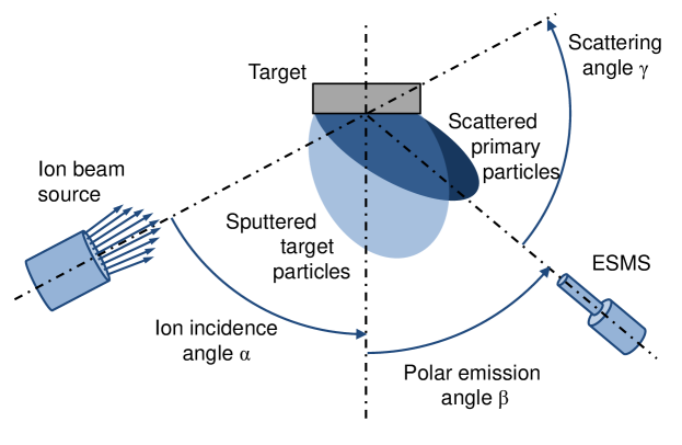
Figure 1 shows a schematic sketch of the ion beam sputter setup inside the vacuum chamber. The setup consists of a broad-beam ion source, a target holder and an energy-selective mass spectrometer (ESMS).
The ion beam source is based on a radio-frequency (RF) discharge with a three-grid multi-aperture extraction system with an open diameter of 16 mm Zeuner et al. (2001). Process gases were Ne, Ar, and Xe with a mass flow rate of 20 sccm, 3.5 sccm and 1.3 sccm respectively. The base pressure in the vacuum chamber was Pa, and the typical process pressure was about Pa. The RF-power was set to 105 W for Ne, 70 W for Ar, and 35 W for Xe, producing a total ion current of about 6 mA in all cases. The target was polycrystalline Si (diameter 100 mm, thickness 3 mm, purity 99.999%).
Energy distributions of sputtered and scattered ions were measured using the energy-selective mass spectrometer (ESMS) Hiden EQP. The differentially pumped ESMS was operated in the energy range from 0 eV up to 1000 eV. The ESMS was mounted at the chamber wall, and the orifice diameter was 0.3 mm.
The target and the ion source are mounted on rotary tables with a common rotation axis. The setup provided a possibility to vary the ion incidence angle and the polar emission angle . The energy distributions of sputtered Si and scattered Ne, Ar and Xe singly charged ions were measured at emission angles in steps of for primary ion energies of 0.5 keV and 1.0 keV, and incidence angles of and . The yields of multiply charged ions are orders of magnitude lower, and they were not considered.
III Modeling and calculations
Energy distributions were also simulated using the Monte Carlo code SDTrimSP Mutzke et al. (2011). This code is widely used for static and dynamic simulations of the sputtering process in various materials. It is based on the binary collision approximation when each collision between atoms is described as an elastic collision with an interaction potential. The energy transfer to electrons is considered as a separate inelastic energy loss.
All simulations were performed with primary ions to achieve sufficient statistics. Ion-solid interactions were described using the Kr-C potential Wilson, Haggmark, and Biersack (1977), and the inelastic energy loss model was equipartition of Lindhard-Scharff Lindhard and Scharff (1961) and Oen-Robinson models Oen and Robinson (1976). The composition of the target for static simulations was assumed to be 90% Si and 10% implanted particles. These numbers are estimates of the average fraction of implanted primary ions in the near-surface layers of the target. The estimates were obtained by dynamic SDTrimSP simulations. The influence of scattering at implanted ions was previously observed for different target materials Feder et al. (2013); Bundesmann et al. (2015); Feder et al. (2014); Lautenschläger et al. (2016). Please note that the code does not account for the formation of secondary ions. We use the resulting simulated distributions as being comprised of the sum of neutral atoms and ions. Later in the text, we will use the term particle to describe either a neutral atom or an ion where we cannot distinguish between them.
The sputtering process in the energy range around 1 keV is commonly described by redistribution of momentum and energy through linear collision cascades. At the same time, target atoms can be sputtered after a single collision, which is designated as directly sputtered. Similarly, the incoming ions can be directly scattered at particles of the surface or near-surface region. Those events can be identified as features in experimental and simulated energy distributions Feder et al. (2013); Bundesmann et al. (2015); Feder et al. (2014); Lautenschläger et al. (2016).
Direct sputtering and scattering can be described in a simplified manner by the conservation of momentum and energy in a binary elastic collision. With the incoming primary ion of mass and initial energy , and a target atom with mass at rest (), the energy of sputtered target particle and scattered primary particle are calculated as
| (1) | |||
| (2) |
where denotes the scattering angle. If , the scattering angles are restricted by . In case of Ar-Si interaction ( u, u), the limit is . If , angles are allowed for scattered particles, and for sputtered particles.
| Ne-Si | Ar-Si | Xe-Si | Ar-Ar; Ne-Ne; Xe-Xe | |||||
|---|---|---|---|---|---|---|---|---|
| [keV] | [∘] | [eV] | [eV] | |||||
| 0.5 | 100 | 57 | - | - | - | - | - | - |
| 80 | 117 | 15 | - | 15 | - | 9 | 15 | |
| 60 | 221 | 122 | - | 121 | - | 73 | 125 | |
| 40 | 350 | 286 | 188 | 284 | - | 170 | 293 | |
| 1.0 | 100 | 115 | - | - | - | - | - | - |
| 80 | 234 | 29 | - | 29 | - | 30 | 30 | |
| 60 | 442 | 243 | - | 242 | - | 250 | 250 | |
| 40 | 700 | 571 | 377 | 569 | - | 587 | 587 |
Eqs. 1 and 2 describe the ideal case. In reality, incident ions face additional energy losses. First, there is the inelastic energy loss to electrons of the target, the so-called ”electronic stopping”. It depends on the energy of incident ion and geometry. Assuming that direct sputtering happens in the 2-3 topmost atomic layers of the target, calculations by SRIM Ziegler, Biersack, and Ziegler (2013) yield values around 7 eV for Ne-Si, 11 eV for Ar-Si and 8 eV for Xe-Si interaction. Second, sputtered and scattered particles have to overcome the surface potential, described by the surface binding energy . For Si is determined to be 4.66 eV Mutzke et al. (2011), and for inert gas atoms the surface binding energy is close to zero.
Table 1 contains calculated energies of direct sputtering and scattering events between an incident primary ion and a Si target atom or an implanted primary ion using Eqs. (1) and (2). Considering Ar-Ar, Ne-Ne and Xe-Xe interaction, Equations (2) and (1) become identical. That means that sputtering and scattering events cannot be distinguished in the experimental energy distribution in this case.
IV Results and discussion
IV.1 Energy distributions of sputtered Si ions
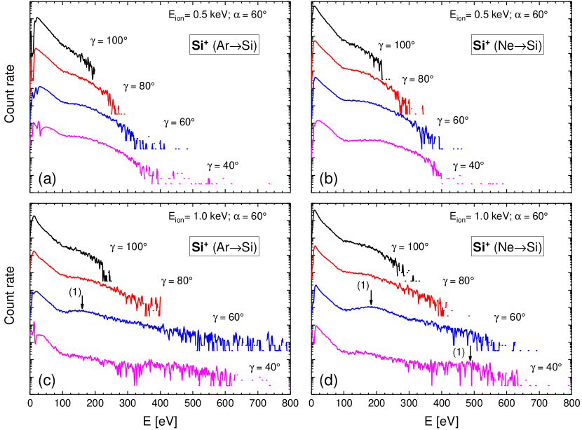
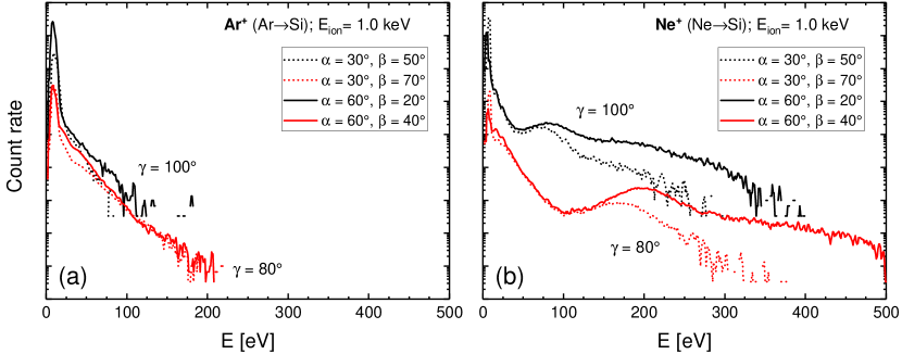
Figure 2 shows measured energy distributions of sputtered ions for the bombardment of a Si target with Ar and Ne ions. All distributions have a low-energy peak followed by a decay proportional to up to 100 eV.
At higher energies, a high energy tail evolves. With decreasing scattering angle, the tail becomes more prominent. The presence of the tail is explained by anisotropy effects Goehlich and Döbele (1996); Franke et al. (1997); Goehlich, Niemöller, and Döbele (1997, 1999); Goehlich, Gillmann, and Döbele (2000); Goehlich, Niemöller, and Döbele (2000); Goehlich, Gillmann, and Döbele (2001); Stepanova and Dew (2001, 2002); Stepanova, Dew, and Soshnikov (2002); Stepanova and Dew (2004). At scattering angles and , broad structures at high energies can be seen (marked by arrows). In previous studies with other target materials Feder et al. (2013); Bundesmann et al. (2015); Feder et al. (2014); Lautenschläger et al. (2016), this structure was associated with direct sputtering since the position of its maximum agreed well with the energy of a direct event (Eq. (1)). The label near the arrow in Figure refers to the cited equation.
Figs. 2(a,c) and 2(b,d) show distributions for various incident ion energies. The overall distribution shape stays almost the same if the same scattering angle is considered. Broad features and the high-energy tail are linearly shifted to higher energies, the distribution is ”stretched” when incident ions have higher energy.
With the change of the process gas from Ar to Ne (Figs. 2(a,b) and 2(c,d)), the shapes of the distributions change only slightly.
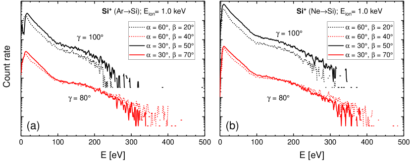
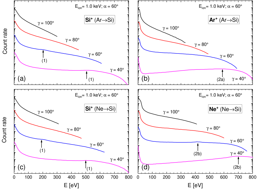
The distributions for various incidence angles in Figure 3 show that the shape of the distributions changes with the scattering angle , and only slightly depends on specific combinations of incident angle and emission angle .
IV.2 Energy distributions of scattered ions
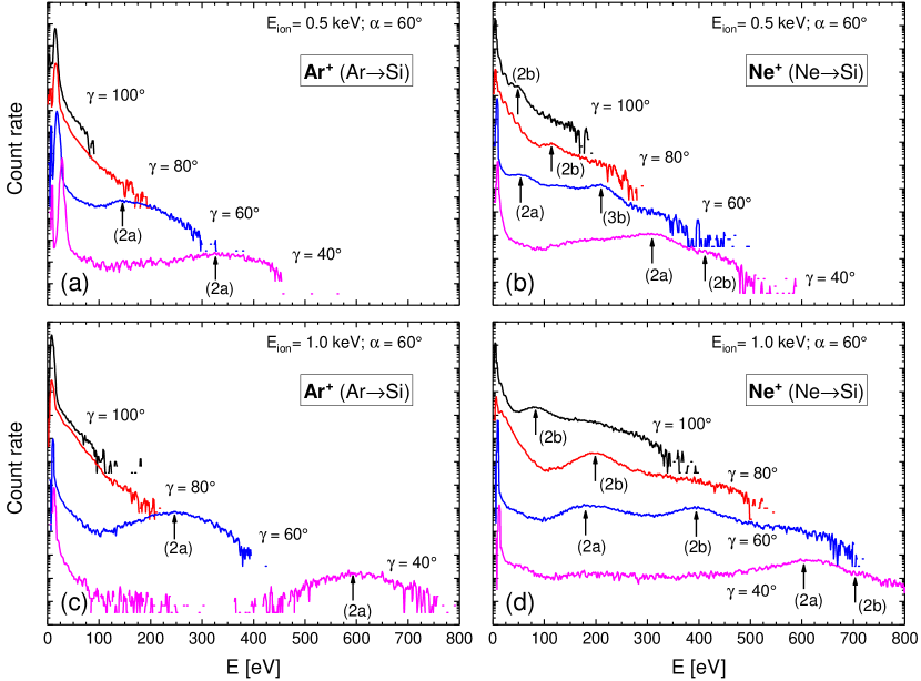
Figure 4 shows measured energy distributions of scattered Ar and Ne ions. The low-energy maximum is followed by an abrupt signal drop. The high-energy tail also extends to higher energies with decreasing scattering angles. At scattering angles and a broad structure with a local maximum appears. This structure (marked by arrows and the number (2a)) is assigned to direct scattering at implanted ions because its energy agrees well with the calculated energy according to the Table 1. In the case of Ne scattering, a second peak shows up at higher energies. This peak is related to direct Ne-Si scattering (Eq. (2)). Direct Ar-Si scattering can only occur for due to the higher atomic mass of Ar, and is indistinguishable from the noise. Implanted primary particles can be directly sputtered as well, but the energy position will coincide with Ar-Ar/Ne-Ne scattering and can therefore not be distinguished from these. Also, lighter Ne ions are scattered more efficiently than heavier Ar ions, therefore showing a more prominent high-energy tail in all cases.
The dependency of energy distributions on incident ion energy (Figs. 4(a,c) and 4(b,d)) is similar to that for sputtered atoms. At higher incident ion energies, the direct scattering features and high-energy tail are shifted to higher energies. The peak positions of the direct event features are in good agreement with the simple calculation (Table 1).
Distributions of scattered Ar ions are also almost independent of specific combinations of incidence and emission angles when curves for the same scattering angle are compared (Figure 5a). However, light Ne ions are directly scattered with higher energies at higher incidence angles (which means lower emission angles) than the heavier Ar ions, as can be seen from Figure 5b. This feature correlates with an increasing role of anisotropy effects for lower scattering angles and lower mass ratios, as was reported in Refs. Roosendaal and Sanders (1980); Lautenschläger et al. (2016).
IV.3 Simulated distributions of secondary particles
The simulated energy distributions in Figure 6 qualitatively reproduce the systematic trends of the measured data, namely peaks of direct scattering and sputtering, and decreasing steepness of the high-energy tail at smaller scattering angles. The positions of resolved peaks agree well with experimental findings and calculations using the simple model (Eqs. 1, 2).
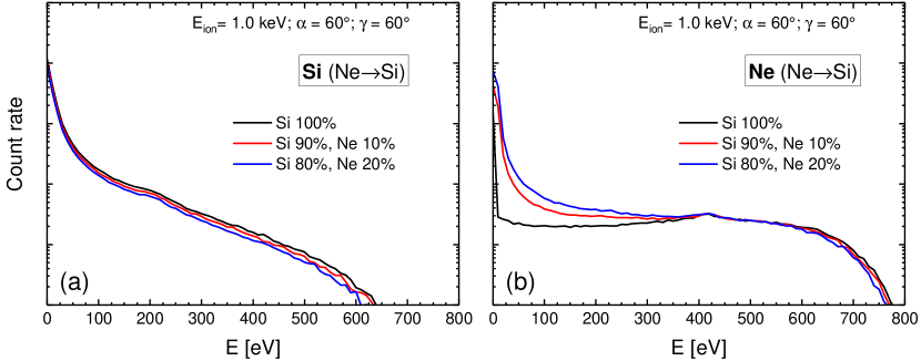
Previously it was specified that the target composition was assumed to contain 90% Si and 10% implanted primary ions, based on the estimates of dynamic simulations. It is interesting to vary the percentage of implanted ions in order to study its effect on the energy distributions of sputtered and scattered particles. Figure 7 shows the case of Ne-Si bombardment at a fixed scattering angle for three target compositions: Si1.0, Si0.9Ne0.1 and Si0.8Ne0.2. Sputtered particles show a slight dependence on the gas contribution. Scattered primary particles show a small increase in numbers in the low-energy part of the distribution with an increase of the gas contribution to the target. This increase is assigned to sputtering of previously implanted particles. The high energy tail stays the same, preserving the features of direct scattering.
IV.4 Discussion
It is interesting to consider systematic correlations between the present data and the results for Ag Feder et al. (2013); Bundesmann et al. (2015), Ge Feder et al. (2014) and Ti Lautenschläger et al. (2016), sputtered by Ar and Xe ions.
In all experiments, the average energy of the sputtered ions increases with decreasing scattering angle and increasing incident ion energy. The change of the primary ion species affects the distributions only slightly. The more important factor is the mass ratio between primary ion and target atom. The closer the ratio to unity, the higher is the maximum energy transferrable in a direct sputtering event (Eq. (1) with ).
In distributions of scattered ions, the broad peaks, assigned to direct scattering at implanted primary ions, were observed for all primary ion/target combinations. Positions of their maxima are independent of the combination, since particles of the same mass interact, but the peaks are higher for lighter atoms. In Ar-Ag, Ar-Ge and Ne-Si configurations, energy distributions also have narrow peaks, assigned to direct scattering on target atoms. In several cases, when the mass ratio is close to unity, the structures assigned to different scattering processes are mixed Lautenschläger et al. (2016).
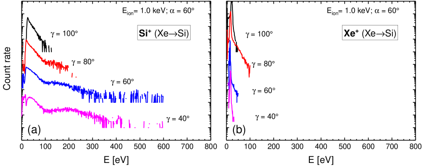
Those trends are additionally verified by measurements for Si bombarded by Xe ions (Figure 8). In contrast to Ne-Si and Ar-Si cases, the ion/target mass ratio is much higher than unity, the average energy of sputtered ions is smaller, and the scattering process is less efficient.
V Summary
In the present work, the energy distributions of sputtered and scattered ions in the ion beam sputtering process of Si were studied experimentally by energy-selective mass spectrometry, and by simulations using the SDTrimSP code in dependence on ion beam parameters and sputtering geometry.
The distributions of sputtered Si ions show similar dependencies as in previous IBSD configurations with other target materials: the average energy of the sputtered ions increases with increasing ion energy and decreasing scattering angle. Also, small differences are observed with the change of the primary species: the closer the mass ratio to unity, the higher the average energy of sputtered ions.
The distributions of scattered Ar ions show the importance of direct scattering on previously implanted primary ions and no signs of scattering at Si. This observation is supported by the fact that the Ar/Si mass ratio is higher than unity, therefore direct scattering happens only at oblique angles. At the same time, in case of the Ne-Si configuration, the distributions reveal the presence of both direct scattering channels. The average ion energy in both Ar and Ne energy distributions also increases with ion energy and decreasing scattering angle. Finally, lighter primary ions tend to scatter more efficiently and with higher average energy, as can be seen from the comparison of energy distributions of Ne+, Ar+ and Xe+ ions.
A comparison of experimental data with simulated energy distributions shows qualitative agreement and the same trends, and the presence of direct scattering and sputtering. Additional simulations show that a 10% variation of the contribution of the target composition does not lead to significant differences in the energy distributions of sputtered and scattered particles.
The results presented in this paper complement systematic studies of IBSD with a very important material. In principle, the discussed trends and effects may also be applicable to other materials. Due to great technological relevance, future measurements in the presence of oxygen will complement the current and recent studies of SiO2 films made with IBSD Mateev et al. (2018).
Acknowledgements.
The authors thank T. Amelal, R. Feder and F. Scholze for fruitful discussions. The software code SDTrimSP is kindly provided by the Max Planck Institute for Plasma Physics (IPP), Germany.References
- Behrisch and Eckstein (2007) R. Behrisch and W. Eckstein, Sputtering by Particle Bombardment (Springer, 2007).
- Goehlich and Döbele (1996) A. Goehlich and H. F. Döbele, “Angle resolved velocity distributions of sputtered aluminum atoms,” Nuclear Instruments and Methods in Physics Research Section B: Beam Interactions with Materials and Atoms 115, 489–492 (1996).
- Franke et al. (1997) E. Franke, H. Neumann, M. Zeuner, W. Frank, and F. Bigl, “Particle energy and angle distributions in ion beam sputtering,” Surface and Coatings Technology 97, 90–96 (1997).
- Goehlich, Niemöller, and Döbele (1997) A. Goehlich, N. Niemöller, and H. F. Döbele, “Angle resolved velocity distributions of sputtered medium Z atoms,” Journal of Nuclear Materials 241-243, 1160–1163 (1997).
- Goehlich, Niemöller, and Döbele (1999) A. Goehlich, N. Niemöller, and H. F. Döbele, “Determination of angle resolved velocity distributions of sputtered tungsten atoms,” Journal of Nuclear Materials 266-269, 501–506 (1999).
- Goehlich, Gillmann, and Döbele (2000) A. Goehlich, D. Gillmann, and H. F. Döbele, “Angular resolved energy distributions of sputtered atoms at low bombarding energy,” Nuclear Instruments and Methods in Physics Research Section B: Beam Interactions with Materials and Atoms 164-165, 834–839 (2000).
- Goehlich, Niemöller, and Döbele (2000) A. Goehlich, N. Niemöller, and H. F. Döbele, “Anisotropy effects in physical sputtering investigated by laser-induced fluorescence spectroscopy,” Phys. Rev. B 62, 9349–9358 (2000).
- Goehlich, Gillmann, and Döbele (2001) A. Goehlich, D. Gillmann, and H. F. Döbele, “An experimental investigation of angular resolved energy distributions of atoms sputtered from evaporated aluminum films,” Nuclear Instruments and Methods in Physics Research Section B: Beam Interactions with Materials and Atoms 179, 351–363 (2001).
- Stepanova and Dew (2001) M. Stepanova and S. K. Dew, “Estimates of differential sputtering yields for deposition applications,” Journal of Vacuum Science & Technology A 19, 2805–2816 (2001).
- Stepanova and Dew (2002) M. Stepanova and S. K. Dew, “Discrete-path transport theory of physical sputtering,” Journal of Applied Physics 92, 1699–1708 (2002).
- Stepanova, Dew, and Soshnikov (2002) M. Stepanova, S. K. Dew, and I. P. Soshnikov, “Sputtering from ion-beam-roughened Cu surfaces,” Phys. Rev. B 66, 125407 (2002).
- Stepanova and Dew (2004) M. Stepanova and S. K. Dew, “Anisotropic energies of sputtered atoms under oblique ion incidence,” Nuclear Instruments and Methods in Physics Research Section B: Beam Interactions with Materials and Atoms 215, 357–365 (2004).
- Thompson (1968) M. W. Thompson, “II. The energy spectrum of ejected atoms during the high energy sputtering of gold,” The Philosophical Magazine: A Journal of Theoretical Experimental and Applied Physics 18, 377–414 (1968).
- Sigmund (1968) P. Sigmund, “Theory of Sputtering. I. Sputtering Yield of Amorphous and Polycrystalline Targets,” Physical Review 184, 383 (1968).
- Lautenschläger et al. (2017) T. Lautenschläger, R. Feder, H. Neumann, C. Rice, M. Schubert, and C. Bundesmann, “Reactive ion beam sputtering of Ti: Influence of process parameters on angular and energy distribution of sputtered and backscattered particles,” Journal of Vacuum Science & Technology A: Vacuum, Surfaces, and Films 35, 041001 (2017).
- Mateev et al. (2018) M. Mateev, T. Lautenschläger, D. Spemann, A. Finzel, J. W. Gerlach, F. Frost, and C. Bundesmann, “Systematic investigation of the reactive ion beam sputter deposition process of SiO2,” European Physical Journal B 91, 45 (2018).
- Bundesmann and Neumann (2018) C. Bundesmann and H. Neumann, “Tutorial: The systematics of ion beam sputtering for deposition of thin films with tailored properties,” Journal of Applied Physics 124, 231102 (2018).
- Okutani et al. (1980) T. Okutani, M. Shikata, S. Ichimura, and R. Shimizu, “Angular distribution of Si atoms sputtered by keV Ar+ ions,” Journal of Applied Physics 51, 2884–2887 (1980).
- Chernysh et al. (2004) V. S. Chernysh, V. S. Kulikauskas, A. S. Patrakeev, K. M. Abdul-cader, and V. I. Shulga, “Angular distribution of atoms sputtered from silicon by 1–10 keV Ar ions,” Radiation Effects and Defects in Solids 159, 149–155 (2004).
- Wittmaack (1984) K. Wittmaack, “Angular dependence of secondary ion emission from silicon bombarded with inert gas ions,” Nuclear Instruments and Methods in Physics Research Section B: Beam Interactions with Materials and Atoms 2, 674–678 (1984).
- Mutzke et al. (2011) A. Mutzke, R. Schneider, W. Eckstein, and R. Dohmen, “SDTrimSP Version 5.00, IPP report 12/8,” Tech. Rep. (Max-Planck-Institut für Plasmaphysik, Garching, 2011).
- Zeuner et al. (2001) M. Zeuner, F. Scholze, B. Dathe, and H. Neumann, “Optimisation and characterisation of a TCP type RF broad beam ion source,” Surface and Coatings Technology 142-144, 39–48 (2001).
- Wilson, Haggmark, and Biersack (1977) W. D. Wilson, L. G. Haggmark, and J. P. Biersack, “Calculations of nuclear stopping, ranges, and straggling in the low-energy region,” Phys. Rev. B 15, 2458–2468 (1977).
- Lindhard and Scharff (1961) J. Lindhard and M. Scharff, “Energy Dissipation by Ions in the kev Region,” Phys. Rev. 124, 128–130 (1961).
- Oen and Robinson (1976) O. S. Oen and M. T. Robinson, “Computer studies of the reflection of light ions from solids,” Nuclear Instruments and Methods 132, 647–653 (1976).
- Feder et al. (2013) R. Feder, C. Bundesmann, H. Neumann, and B. Rauschenbach, “Ion beam sputtering of Ag - Angular and energetic distributions of sputtered and scattered particles,” Nuclear Instruments and Methods in Physics Research, Section B: Beam Interactions with Materials and Atoms 316, 198–204 (2013).
- Bundesmann et al. (2015) C. Bundesmann, R. Feder, T. Lautenschläger, and H. Neumann, “Energy Distribution of Secondary Particles in Ion Beam Deposition Process of Ag: Experiment, Calculation and Simulation,” Contributions to Plasma Physics 55, 737–746 (2015).
- Feder et al. (2014) R. Feder, C. Bundesmann, H. Neumann, and B. Rauschenbach, “Ion beam sputtering of germanium - Energy and angular distribution of sputtered and scattered particles,” Nuclear Instruments and Methods in Physics Research, Section B: Beam Interactions with Materials and Atoms 334, 88–95 (2014).
- Lautenschläger et al. (2016) T. Lautenschläger, R. Feder, H. Neumann, C. Rice, M. Schubert, and C. Bundesmann, “Ion beam sputtering of Ti: Influence of process parameters on angular and energy distribution of sputtered and backscattered particles,” Nuclear Instruments and Methods in Physics Research B 385, 30–39 (2016).
- Ziegler, Biersack, and Ziegler (2013) J. F. Ziegler, J. P. Biersack, and M. D. Ziegler, “SRIM - The Stopping and Range of Ions in Matter,” http://www.srim.org/ (2013).
- Roosendaal and Sanders (1980) H. E. Roosendaal and J. B. Sanders, “On the energy distribution and angular distribution of sputtered particles,” Radiation Effects 52, 137–143 (1980).