Designing modular D printed reinforcement of wound composite hollow beams with semidefinite programming
Abstract
Fueled by their excellent stiffness-to-weight ratio and the availability of mature manufacturing technologies, filament wound carbon fiber reinforced polymers represent ideal materials for thin-walled laminate structures. However, their strong anisotropy reduces structural resistance to wall instabilities under shear and buckling. Increasing laminate thickness degrades weight and structural efficiencies and the application of a dense internal core is often uneconomical and labor-intensive. In this contribution, we introduce a convex linear semidefinite programming formulation for truss topology optimization to design an efficient non-uniform lattice-like internal structure. The internal structure not only reduces the effect of wall instabilities, mirrored in the increase of the fundamental free-vibration eigenfrequency, but also keeps weight low, secures manufacturability using conventional three-dimensional printers, and withstands the loads induced during the production process. We showcase a fully-automatic procedure in detail for the design, prototype manufacturing, and verification of a simply-supported composite machine tool component, including validation with roving hammer tests. The results confirm that the 3D-printed optimized internal structure almost doubles the fundamental free-vibration eigenfrequency, allowing to increase working frequency of the machine tool, even though the ratio between elastic properties of the carbon composite and the ABS polymer used for 3D printing exceeds two orders of magnitude.
keywords:
Topology optimization , internal structure , semidefinite programming , additive manufacturing , elastic instabilities , experimental validation1 Introduction
Offering excellent stiffness-to-weight ratios, high damping, and a low sensitivity to fatigue and corrosion, carbon fiber reinforced polymers (CFRPs) are employed in high-tech applications, including bodies of racing cars in automotive [1], propulsors and turbines in naval [2, 3], wing boxes and ailerons in aerospace [4], and rocket bodies in the space industry [5]. Considerable attention has been therefore paid to methods for optimizing structural performance of these laminates, particularly the laminate layup [6, 7]. To concurrently maximize bending stiffness and keep weight low, the outer dimensions of these structures tend to be maximized, while the wall thickness is minimized. The “thin-walledness” of the resulting structures, combined with their anisotropy, renders them highly sensitive to shear and wall buckling instabilities manifested in low fundamental free-vibration eigenfrequencies.
Below, we review common approaches to topology optimization that reduce wall instabilities by designing an internal structure, Section 1.1. Section 1.2 provides a brief introduction to semidefinite programming and highlights several applications in structural optimization. Finally, Section 1.3 reveals the merits of designing internal structures using semidefinite programming.
1.1 Topology optimization
Topology optimization techniques [8] provide the means for reducing wall instabilities when designing sufficiently stiff yet lightweight structures. In the simplest setting—beam cross section optimization—we search an optimal two-dimensional cross-sectional shape or a stiffening of structures whose outer shape is predefined [9]. Blasques [10], for example, maximized the fundamental free-vibration eigenfrequency while accounting for the mass and shear center position constraints; Nguyen et al. [11] optimized cross-sections of prismatic beams to maximize their buckling loads.
The design of optimal core sandwich structures, whose skins are stiffened by a thick core is a related challenge. For honeycomb, solid, truss, and foam rectangular panels under in-plane compression or shear loads, optimal periodic topologies can be found analytically by considering the optimality criterium of all failure modes occurring simultaneously [12]. For complex boundary conditions, parametric shape-optimization studies are usually performed. Wang and McDowell [13] studied the geometry of a metal honeycomb sandwich beam core under torsion and bending and Xu and Qiu [14] optimized the lattice core of a composite sandwich panel to increase the fundamental eigenfrequency while accounting for uncertainties in the model. They concluded that bending eigenfrequencies increase with increasing strut thicknesses, with an increase in the elastic and shear modulus of the composite, and with a decrease in density. Although Daynes et al. [15] optimized spatially-graded lattice structures within a single sandwich panel domain, surprisingly, almost no prior research seems to have stepped beyond parametric intuition-based designs [16, 17], the rare exception being the multi-scale topology optimization approach investigated by Coelho and Rodrigues [18].
Questioning whether, where, and how to stiffen already engineered designs in order to further improve their structural performance constitutes the central question of the reinforcement problem [19, 20], superseding the former dimensional reduction and periodicity assumptions. Initial studies in this area have considered maximization of the fundamental eigenfrequency [20] and improving the structural frequency response of plane elastic structures [21] using the homogenization and optimality criteria methods, respectively.
Using the ground structure approach for topology optimization of truss structures, Bendsøe et al. [22] fixed cross-sectional areas of a set of bars and searched for their stiffest truss reinforcement, a (non-smooth) convex quadratic programming formulation. Alternatively, the effect of a fixed boundary structure has been approximated by an appropriate application of nodal forces to the ground structure [23, 24], but this choice influences, however, the optimized design.
In the setting of continuous topology optimization, Luo and Gea [25] developed a systematic optimization approach for the topology and orientation design of composite stiffeners of plates and shells in both static and dynamic settings, and Wang et al. [26] optimized the overall structural rigidity of an automobile body through a maximization of the fundamental eigenfrequency. In aerospace applications, Maute and Allen [27] optimized a wing’s internal structure, subjected to fluid-surface interactions; Aage et al. [28] performed an extremely large-scale optimization of the internal structure of a Boeing 777 wing, while avoiding the traditional rib and spar designs [29]. In military applications, topology optimization was the basis for the design of additively-manufactured lattice-reinforced penetrative warheads [30] and for optimizing the layout weight of stiffeners in composite submarines subjected to nonsymmetric wave slap loads [31].
Other methods relevant to internal structure design have arisen in conjunction with recently introduced coating and infill optimization problems. Clausen et al. [32] developed a formulation for the optimization of (uniformly) coated structures, wherein a base material, infill, was surrounded by another material at the interfaces, finding a porous, complex infill significantly improves both structural buckling resistance and robustness to local perturbations when compared to optimized solid structures of equal weight and similar stiffnesses [33, 34]. In three dimensions, optimized designs further exploit the merits of closed shell surfaces through the sandwich effect [34].
Inspired by natural, bone-like microstructures, Wu et al. [35] optimized a spatially non-uniform porous infill, Wang et al. [36] developed a sequential approach for generating graded lattice mesostructures, and Zhu et al. [37] introduced a novel asymptotic-analysis-based homogenization approach. All these methods automatically design stiff yet porous infills for additive manufacturing products while superseding the traditional pattern-based designs [38]. Finally, Wu et al. [39] extended their approach to the ultimate setting of a concurrent optimization of coated structures and porous infills, and Groen et al. [40] have developed a homogenization-based method to accelerate solutions.
1.2 Semidefinite programming
It has been shown in recent decades that several structural optimization problems can be modeled as semidefinite programs. Linear semidefinite programming (SDP) is a subset of convex optimization of the form
| (1a) | ||||
| (1b) | ||||
| (1c) | ||||
and involves minimization of a linear function (1a) over a spectrahedron, which is an intersection of an affine space (1b) with the cone of symmetric positive semidefinite matrices (1c). In (1c), the notation “” enforces positive semidefiniteness of the left hand side. Due to the linear dependence of on (1b), (1c) is commonly referred to as a linear matrix inequality (LMI).
Applications of semidefinite programming to structural design were pioneered by Ben-Tal and Nemirovski [41], de Klerk et al. [42], and Vandenberghe and Boyd [43] who developed formulations for minimum-compliance and weight truss topology optimizations. The main added value of SDP lies in its ability to effectively avoid the non-differentiability of multiple eigenvalues for free-vibrations [44, 45] and buckling [46, 47], robust optimization [48], and bounds improvement for optimization problems in a discrete setting [49]. Semidefinite programming has also found applications in optimal materials design, the Free Material Optimization approach [50], or in the limit analyses [51].
1.3 Aims and novelty
In this contribution, we consider an industrial problem of designing the least-weight internal structure of a thin-walled filament-wound composite machine tool component prone to shear and buckling wall instabilities. The beam laminate was designed for bearing dynamic loads, allowing us to describe the wall instabilities naturally in terms of free-vibrations eigenfrequencies.
In current production process, the wall instabilities are reduced by inserting a uniform foam core structure into the beam interior, an uneconomical and labor-intensive process. Conversely, we have aimed to automatically design a structurally-efficient internal structure which can easily be manufactured using conventional low-cost D printers.
To this goal, we extended the convex (linear) semidefinite programming formulation introduced by Ohsaki et al. [44] and Ben-Tal and Nemirovski [48] to design globally-optimal least-weight lattice-like internal structures and apply it to increasing the fundamental eigenfrequency and decreasing the compression-molding compliance of a thin-walled composite beam prototype. Note that Achtziger and Kočvara [45] avoided prescribed structural elements but allowed for a non-structural mass and Ohsaki et al. [44] did not consider prescribed mass or stiffness.
After introducing the case study of a simply-supported CFRP beam design in Section 2, we develop its finite element representation in Section 3.1. For this representation, a semidefinite programming formulation for truss topology optimization of internal structures is developed in Section 3.2. Having designed the optimal internal structure, we post-process the optimization outputs and export, in a fully-automated way, the internal structure for additive manufacturing in Section 3.3. During manufacturing, the internal structure serves as the support for carbon fibers in the filament-winding production phase, and a prototype is created. Section 4 describes verification and experimental validation of the prototype and concludes that its response agreed well with the model prediction.
2 Case study
| Layer | [GPa] | [GPa] | [GPa] | [-] | [-] | [] | [kg/m3] | [mm] |
|---|---|---|---|---|---|---|---|---|
| (casing) |
As the basic structure, we consider a prismatic, laminated composite beam mm long, with a mm thin-walled cross-section mm thick, Fig. 1(b). According to current manufacturing technology, beam production consists of several steps, in which a supporting structure made of manually processed high-density foam is wound biaxially with a combination of ultra high modulus (UHM) and high modulus (HM) carbon fibers saturated with epoxy resin. The supporting structure prevents cross-section distortions induced by compression-molding loads as shown in Fig. 1(c). Subsequently, the beam is cured, the supporting structure is pulled out, and the beam outer surface is finalized.
The final product is exposed primarily to loads that induce bending. For this purpose, most of the carbon fibers are aligned with the beam’s longitudinal axis (layer in Table 1), denoted by in Fig. 1(a), whereas the remaining layers reduce the susceptibility to delamination. See Table 1, where all layers are listed by their orientations relative to the beam’s longitudinal axis, . This layered composition reliably transmits the design forces to the supports, and is thus fully sufficient in this sense.
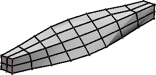
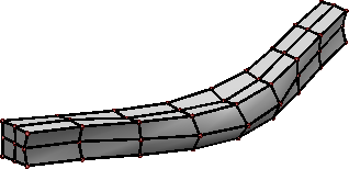
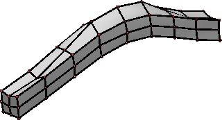
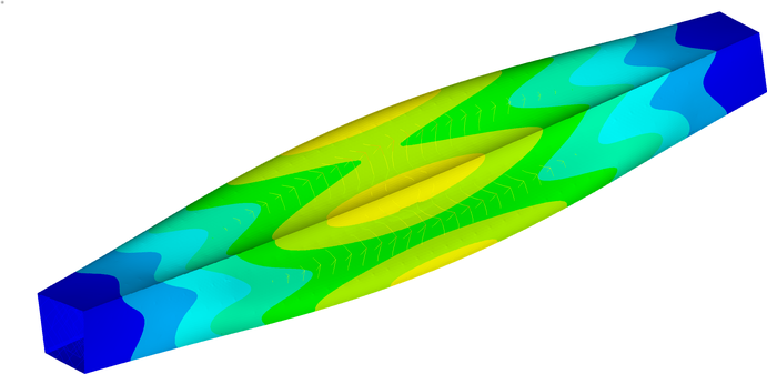
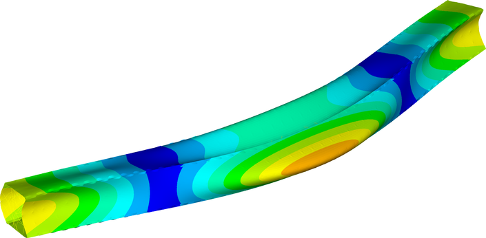
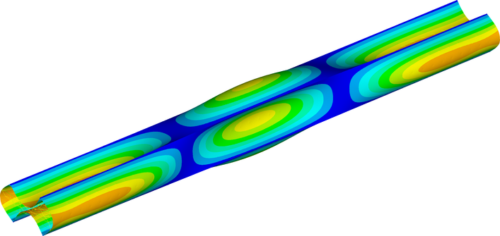
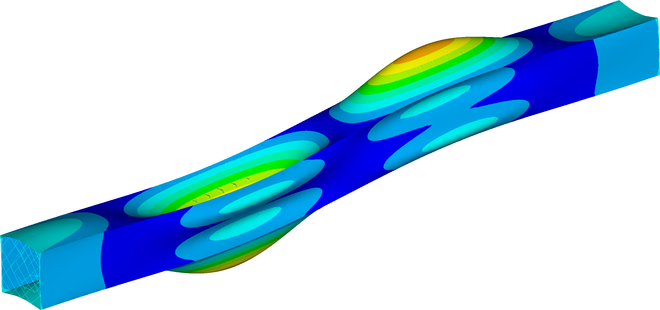
Attributed to transversely isotropic material properties, the beam’s walls are, however, prone to elastic wall instabilities under shear and buckling, which also manifests in free-vibration modes and frequencies of the non-reinforced beam. Figure 2 confirms that the first fundamental eigenmode with a frequency of Hz corresponds to shear wall instabilities, whereas the second eigenmode combines bending with buckling; all higher eigenmodes (not shown) exhibit similar wall instabilities. Because the fundamental eigenfrequency limits the maximum working frequency of the machine part, its increase is of considerable interest.
Although the effect of these instabilities can be reduced by additional laminate layers or by also keeping the uniform foam structure for operational loads, the added weight, decrease in the bending eigenfrequencies, and labor-intensive production process render these approaches both time-inefficient and uneconomical.
3 Optimal design of internal structure
The aim of this section is to cast the optimal internal structure design problem in the form of a linear semidefinite program (1). The internal structure has to withstand compression molding loads with a maximum deflection bound, while the internal structure is temporarily supported by a steel mandrel passing through the beam interior, Fig. 1(c). Most importantly, the internal structure is supposed to increase the beam fundamental eigenfrequency via reduction of wall instabilities.
In this section, we first describe the finite element model of the composite beam. This finite element model serves then as the basis for establishing the optimization problem formulation, yielding an optimal internal structure design. The section is concluded by discussing post-processing steps necessary to maintain manufacturability of the design.
3.1 Finite element model
The outer composite beam surface is discretized with shell elements which are supplied with the material properties from Table 1. The beam internal structure is modeled by bar (truss) elements, with the isotropic Acrylonitrile Butadiene Styrene (ABS) material properties [52]: elastic modulus GPa, Poisson ratio , and density kg/m3.
Special care needs to be paid to establishing a rigid connection between the internal structure and the carbon composite. The so-called casing, see Fig. 3, which is a mm thin layer of printed beam walls, further prevents leaking of the epoxy resin into the beam’s interior. Casing is modeled as the bottom layer of the laminate composition, recall Table 1.
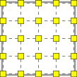
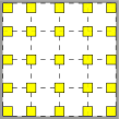
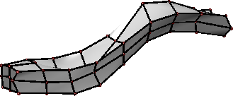
The finite element model for the optimization part was developed in Matlab. In this model, the outer laminate was modeled with four-node Mitc4 elements [53]. The composite beam interior was discretized into the ground structure [54], a set of admissible truss111Based on comparative simulations (not shown), modeling internal structure with trusses or beams leads to an insignificant difference in the structural response which enabled us to employ truss topology optimization approaches in Section 3.2. elements, whose cross-sections we search in the optimization part. The ground structure was constructed from modular building blocks shown in Fig. 4, to guarantee manufacturability of the entire internal structure with D printing. Note that the bars placed within the location of the steel mandrel were removed from the ground structure and that the shell element nodes coincided with the ground structure nodes, resulting in a rather coarse discretization of the outer layer.
3.2 Formulation of the optimization problem
3.2.1 Non-convex formulation
Adopting the previously described discretization, our goal is to find the cross-sectional areas of bars in the minimum-weight (or volume) ground structure, such that the fundamental eigenfrequency exceeds the user-defined lower threshold , taken as Hz in what follows, while exhibiting limit displacements of the reinforced structure during the compression molding load case. This leads to the following optimization problem
| \linenomathWithnumbersAMS | ||||||
| (2a) | ||||||
| (2b) | ||||||
| (2c) | ||||||
| (2d) | ||||||
| (2e) | ||||||
with
| (3) |
In this formulation, the vector appearing in the objective function (2a) collects the bar lengths in the truss ground structure. The Rayleigh quotient in (2b) involves stiffness, , and mass, , matrices of the outer shell structure for free-vibration analysis together with stiffness, , and mass, , matrices of the internal structure. The design-dependent contributions of the internal structure are obtained as
| (4) |
where and stand for the stiffness and mass matrix of individual bars in the free-vibration (fv) setting, respectively; is the -th component of and the limit fundamental free-vibrations eigenvalue.
The constraints (2c) and (2d) address the compression-molding (cm) load case, recall Fig. 1(c). Specifically, (2c) introduces the generalized nodal displacements in response to the generalized load vector corresponding to the compressive load, and denotes the displacement components of . The stiffness matrix corresponding to this load case consists again of the design-independent, , and design-dependent, , parts; the latter is obtained as in (4). The symbol denotes a column vector of all ones. Notice that the stiffness matrices in (2b) and (2c) differ because of different boundary conditions in the operational, Fig. 1(a), and manufacturing, Fig. 1(c), load cases. The constraint (2d) requires the displacement components of to remain smaller than the user-defined limit value , considered to be mm in this study. Finally, (2e) requires the cross-sectional areas of the bars to be non-negative and smaller than mm2, a value set by the additive manufacturing constraints.
A closer comparison of the optimization problem of Eq. (2) and that of Eq. (1) reveals that the problem of Eq. (2) lacks the structure of a semidefinite program. Namely, the objective function (2a) and the matrices in the constraints depend affinely on the design variables, . However, the constraints (2b) and (2c) are non-convex as the stiffness and mass matrices may become singular when the zero lower-bound for cross-sectional areas is attained in (2e). Moreover, (2b) might become non-differentiable when an eigenvalue with multiplicity higher than one is encountered. Altogether, this renders the problem (2) extremely difficult to solve in its original form. In the following section, we show how to re-cast the problem of Eq. (2) as a linear semidefinite programming problem.
3.2.2 Convex semidefinite program
Similar eigenvalue constraints such as (2b) have already been studied in detail by Ohsaki et al. [44] and Achtziger and Kočvara [45]. Their results allow us to rewrite (2b) equivalently as a convex LMI
| (5) |
where the left hand side expression is a linear function of . This constraint also avoids the non-differtiability of multiple eigenvalues, see, e.g., [45], and effectively eliminates the kinematic variables from the problem formulation.
To attain convexity of the final formulation, the compression molding constraints (2c)–(2d) must be enforced only approximately in the form of the LMI [42, 43, 48]:
| (6) |
in which denotes a prescribed upper bound on compliance (work done by external forces) of the compression molding load case. As found from parametric studies (not shown), an appropriate value of the bound is provided as
| (7) |
where stands for the compliance of the non-reinforced structure:
| (8) |
Here, and are constructed from and , respectively, by application of appropriate boundary conditions. For this particular problem, this compliance bound resulted in a maximum deflection of mm.
The final linear semidefinite programming formulation eventually reads as
| \linenomathWithnumbersAMS | ||||||
| (9a) | ||||||
| (9b) | ||||||
| (9c) | ||||||
| (9d) | ||||||
This formulation now possesses the structure of the linear semidefinite program introduced in Section 1.2, and thus can be solved efficiently via modern interior-point methods.
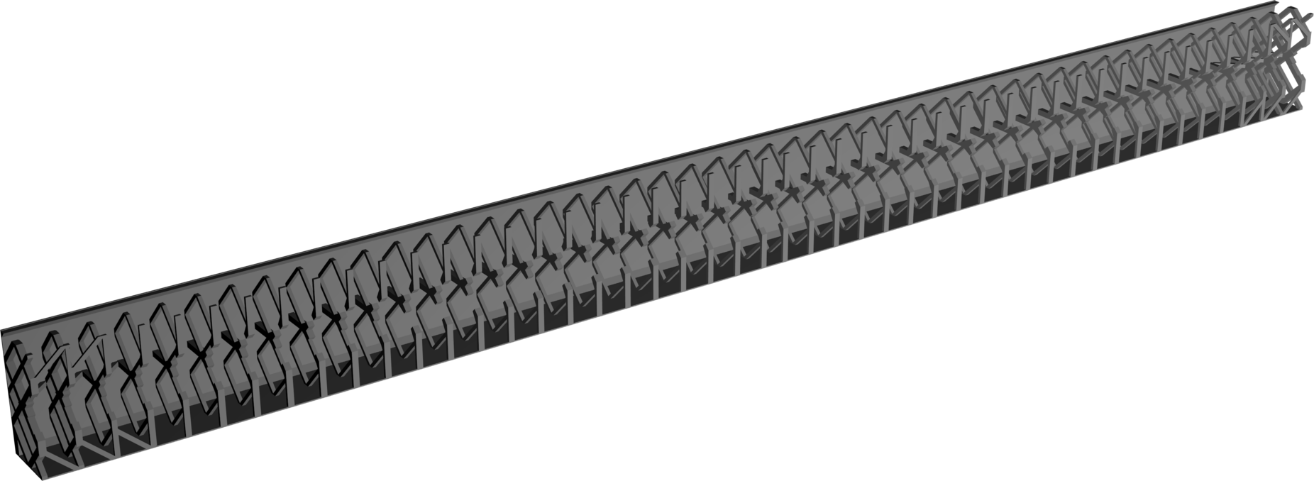
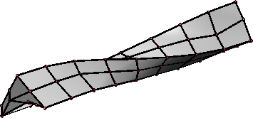
For numerical solution, we adopted the state-of-the-art industrial optimizer Mosek [55]. After discretization, the problem in Eq. (9) has admissible bars in total, with the corresponding sizes of the linear matrix inequalities (free-vibration, Eq. (9b)) and (compliance, Eq. (9c)). After tweaking the optimization problem with the steps outlined in the following subsection, the optimization process itself required GB of memory, and terminated after core hours running on Intel Xeon Gold 6130 processors at the MetaCentrum222https://metavo.metacentrum.cz/ virtual organization cluster. The resulting distribution of the optimal internal structure is shown in Fig. 5. Note that the internal structure increased the original weight of the beam, g, by an additional g ( g of casing and g of reinforcing bars).
Improving solver performance
To reduce the number of iterations and time per iteration to solve problem (9), we rescale the cross-sectional areas to obtain the optimal values of the order of mm. Second, to improve both the numerical stability and convergence of the algorithm considerably, we rescale Eqs. (9b) and (9c) with the square root of the Frobenius norm estimates of (Eq. (9b)), and (Eq. (9c)). Finally, using the static condensation, Appendix A, and Schur complement, Appendix B, decomposition techniques, the sizes of LMIs reduce to (free-vibration, Eq. (9b)) and (compliance, Eq. (9c)). Consequently, memory usage was decreased from GB to GB, and the solution process was accelerated by (from to core hours).
3.3 Post-processing
Manufacturing of the optimal design is preceded by three preprocessing steps addressing individual bars, segmentation into modules, and conversion to a solid model. Note that we checked that none of the steps led to the constraint violation and have a rather negligible impact on the objective function, i.e., after all post-processing steps, the internal structure volume increased from cm3 to cm3.
Bars post-processing
In the initial step of module post-processing, we assign square cross-sections to each bar with the square side length according to the optimal area, . Next, we check potential intersection of bars and place a node at each intersection, which subdivides them into two and defines the new element lengths. Third, for each bar, we set the cross-sectional size to at least , because more slender bars are difficult to manufacture with the Prusa D printers used in this study. In addition to the optimized bars, the internal structure is extended with short L-shaped beams that ensure mechanical interaction between the internal structure and the steel mandrel, thus defining an empty mm space along the beam longitudinal axis for its insertion, see Figs. 9 and 8a.
re-alignment
left end center right end left end center right end
Segmentation
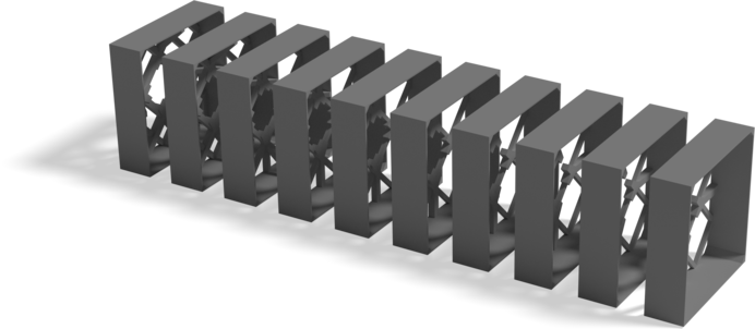
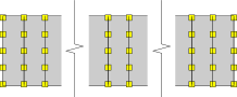
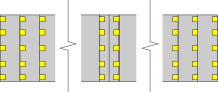
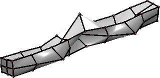
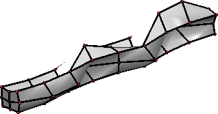
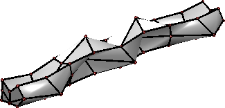
To enable parallel manufacturing with conventional 3D printers, we split the optimized internal structure into segments of approximately 20 mm in length, see Fig. 6 where ten selected segments are shown, to be assembled later on the steel mandrel. Such segmentation requires re-alignment of bars within each beam cross-section and along the beam longitudinal axis to ensure the correct external beam dimension and a clearly defined interface among adjacent modules, see Fig. 7 for an illustration. Note that segment production does not require any supporting material when printed along the beam longitudinal axis , which would be impossible when printing the internal structure as a single-piece product.
Solid conversion
Axial model conversion is performed independently and in parallel for each node of the ground
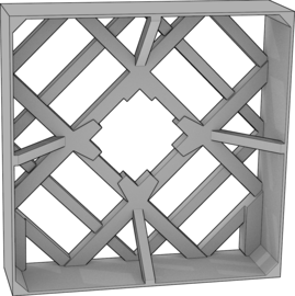
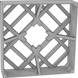
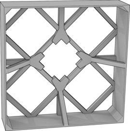
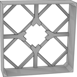
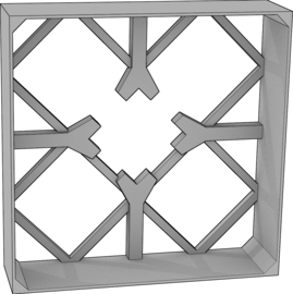
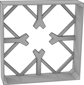
structure. We determine first all bars attached to the considered node, elongate them by one half of their cross-sectional side lengths at both of their ends, and cut the more distant half of each of these bars off. These half-bars are then modeled by a mesh-based representation. Geometries of individual nodes then result from the mesh-boolean operations performed with the Cork333https://github.com/gilbo/cork library. Finally, the overall segment geometry consists of the union of all nodal geometries, see Fig. 9 for typical topologies of post-processed segments, and can be readily exported to patch-based Stl file format, for example.
4 Results
4.1 Manufacturing
After the automated export of the optimized internal structure into Stl format, the part was additively manufactured using the Fused Deposition Modeling method with Prusa i3 MK3 printers. Printed segments were inserted on a mm steel mandrel of mm wall thickness, with its surface lubricated with Vaseline to simplify the pull-out process, and connected with acetone etching and a thin layer of epoxy glue.
The prototype beam was produced by CompoTech Plus company using the filament winding technology with axial fiber placement. This technology relies on the positioning of the tows of carbon fibers impregnated by the epoxy resin on the casing, placed in specified directions and specified quantity to reach expected dimensions and mechanical properties of the final product. The casing defines the internal shape of the beam and acts as an internal mold. After the fiber placement operation, the product (with still liquid resin) is placed into the press, the outer shape is formed, and the composite is consolidated. In the press, the product hardens at the room temperature. Finally, the prototype, Fig. 10, is postcured at the elevated temperature of C.
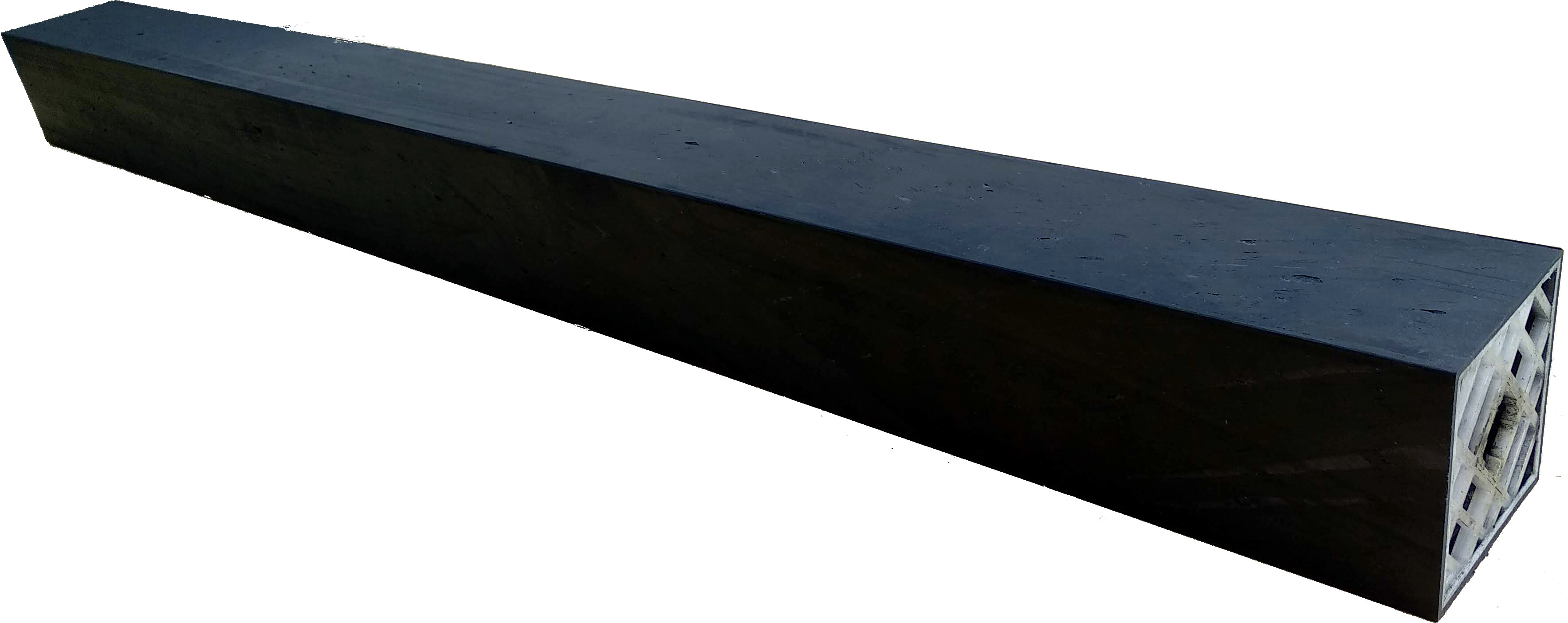
The successful manufacturing process was followed by inspection of the prototype using an endoscope camera. Video and photograph sequences, see Fig. 8, revealed that the internal structure successfully withstood the compression molding pressure without any significant visual defects. The minor deviations from the assumed model reside in a small amount of Vaseline residue and slight leakage of the epoxy resin through casing interfaces. Another difference appeared in the increased outer dimensions of the beam, mm on average, caused by an insufficiently closed press cover. The total prototype weight of kg was therefore g higher than the model predictions due to the additional epoxy resin.
4.2 Verification
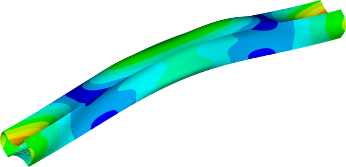
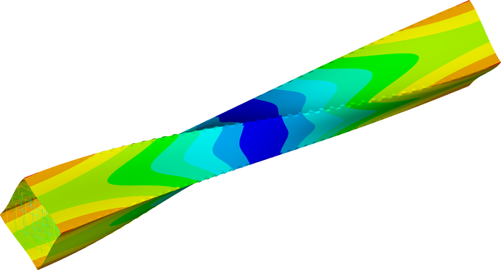
Recall that in the optimization we required increasing the fundamental free-vibration eigenfrequency above Hz. To check this value, we employed an independent model in Ansys. Compared to the model used for optimization, this model employs the dimensions measured in-situ, more refined discretization of the outer shells (element type Shell181), and models the internal structure with beam elements (Beam188) instead of trusses. Besides, the composite shells are supplemented with an additional layer of epoxy resin to account for the increased epoxy content. As a result, the model predicts that the beam fundamental eigenfrequency was increased by % from Hz to Hz, compare Figs. 2 and 11. The effect of wall instabilities was reduced jointly in all the remaining eigenmodes (not shown).
Even though the fundamental eigenfrequency did not exceed the limit value, we find these results satisfactory because of two reasons: First, we attribute this discrepancy mainly to the manufacturing imperfections, which can be attributed to the prototype character of the manufacturing process and can be easily resolved in serial production. Second, the constraint violation is comparable to the difference between numerics and experiments as shown in the next section.
4.3 Validation
Dynamic response was validated with the roving hammer test in the free-free-vibration setting because it eliminates the need to reproduce the simply supported kinematic boundary condition in the experiment. To this goal, the beam was suspended at one of its ends, three piezoelectric acceleration transducers Type 4507B005 Brüel&Kjaer were placed on the beam’s outer surface, two of which were located in the middle of adjacent sides of the beam’s cross-section at one-eighth of the beam’s length, and the third one was placed at the corner of the beam, Fig. 12. Two adjacent sides of the beam surface were marked with a regularly spaced grid of points, on each side. These points then served as the excitation points for the impact hammer Type 8206 Brüel&Kjaer equipped with a force transducer.
Measurement was realized using data acquisition front-end hardware Type 3560B Brüel&Kjaer. The frequency response functions (FRFs) were evaluated from the recorded response (acceleration) and excitation (force) using the Fast Fourier Transform for all 54 points. The natural frequencies and mode shapes were evaluated from the FRFs with MEscope software developed by the Vibrant Technology company.
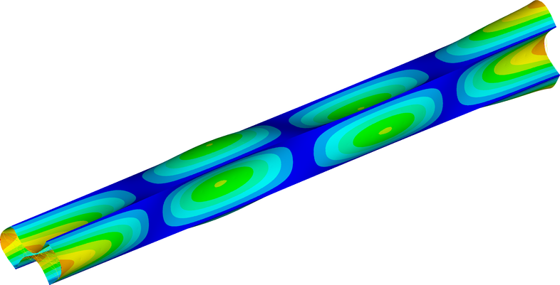
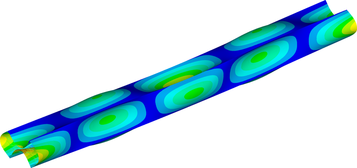
Experimentally determined natural modes and the values of natural eigenfrequencies, Fig. 13 top, were compared with the results of numerical simulations, Fig 13 bottom. Direct comparison in Table 2 reveals sufficient agreement of up to for eigenfrequencies of shear, bending, and torsional eigenmodes. In the case of buckling, we failed to measure the first and second buckling natural modes, and for the higher eigenmodes, the model predictions underestimate the natural frequencies by more than . We attribute these deviations to the overall difficulty of measuring the buckling natural modes and to the manufacturing defects discussed in the previous section.
| Eigenmode | [Hz] | [Hz] | [Hz] | [] |
|---|---|---|---|---|
| First shear | ||||
| First bending | ||||
| First bending | ||||
| Third buckling | ||||
| First torsion | ||||
| Fourth buckling | ||||
| Fifth buckling | ||||
| Sixth buckling | ||||
| Second bending |
5 Summary and outlook
This contribution introduces and investigates a unique, fully-automatized procedure from an idea to prototyping, with applications to the manufacturing of thin-walled structural composite hollow beams. In particular, the considered prototype product is stiffened with a low weight internal structure designed by an efficient convex linear semidefinite programming formulation. This formulation increased the fundamental free-vibration eigenfrequency above a specified threshold value while avoiding the traditional issue of non-differentiability of multiple eigenvalues [45], and limited structural compliance of a compression-molding load case. The optimization output of the non-uniformly distributed lattice-like internal structure was further automatically post-processed and converted into a solid model ready for support-less additive manufacturing.
Our methodology was verified by designing and producing the simply-supported CFRP beam prototype. Optimization yielded an internal structure of g which increased the fundamental eigenfrequency by and limited the effect of wall instabilities. Moreover, the deflections within the compression-molding load case were limited to mm.
After a successful prototype production, the structural response was validated using the roving hammer test, which showed that bending, torsional, and shear eigenmodes exhibited good agreement with model predictions. For the wall buckling eigenmodes, however, the finite element model underestimated the natural frequencies by almost . We attribute this to difficulties in measuring these natural modes and to manufacturing defects associated with compression-molding deformations of the casing.
Improving the structural response with a material more than two orders of magnitude more compliant when compared to CFRP suggests concentrating on substituting ABS with high-stiffness continuous carbon fiber in future studies. Another essential future enhancement resides in accelerating the optimization algorithm by exploiting the range-space sparsity [56] associated with the segment-based internal-structure decomposition.
Acknowledgments
We thank Edita Dvořáková for providing us with her implementation of the Mitc4 shell elements [57], and Ondřej Rokoš and Stephanie Krueger for a critical review of the initial versions of this manuscript.
The work of Jan Novák and Robin Poul was supported by the Technology Agency of the Czech Republic, through the project TAČR TH02020420. Marek Tyburec, Jan Zeman, and Matěj Lepš acknowledge the support of the Czech Science Foundation project No. 19-26143X.
Access to computing and storage facilities owned by parties and projects contributing to the National Grid Infrastructure MetaCentrum provided under the program ”Projects of Large Research, Development, and Innovations Infrastructures” (CESNET LM2015042), is greatly appreciated.
Data availability
The raw/processed data required to reproduce these findings cannot be shared at this time due to legal or ethical reasons.
Appendix A. Static condensation of static LMI
Consider the equilibrium equation
| (10) |
split into two sets of equations
| (11) |
such that only the principal submatrix depends affinely on 444In the context of this article, the matrix comprises the degrees of freedom of the truss ground structure, contains the remaining (rotational) degrees of freedom, and is the coupling term.. Assuming that the system (10) is solvable uniquely for some , i.e., it holds that , where “” denotes positive definiteness of the left hand side. Note that is sufficient for verification that no rigid movement within the structure can occur. Because is therefore invertible, the degrees of freedom can be expressed from the second row in terms of
| (12) |
and inserted back into the first row,
| (13) |
Structural compliance (work done by external forces) is expressed as
| (14) |
After inserting (12) and acknowledging that is Hermitian, we obtain
| (15) |
i.e., compliance of the condensed problem (13) and a constant term. Because the compliance of the condensed problem is positive by definition, the constant term represents a non-negative lower bound on compliances achievable by the internal structure design.
Appendix B. Reducing size of free-vibration LMI
In the case of the free-vibration constraint, we need to directly apply the (generalized) Schur complement lemma. Beginning with reordering of rows and columns, we split the symmetric LMI (9b) such that only the and matrices are functions of , and the other blocks are constant,
| (19) |
For the (standard) Schur complement trick we require [58, Proposition 16.1]. Since (boundary conditions exclude rigid motions), and by definition, we only need to secure that the fundamental eigenfrequency of the generalized eigenvalue problem
| (20) |
with , is strictly greater than .
Let us therefore first assume that . Then, the inverse of exists and (19) can be rewritten equivalently using the Schur complement lemma into a smaller-sized LMI
| (21) |
Second, consider that . Because the matrix is indefinite for any , which renders the original LMI (19) infeasible, the eigenfrequency constitutes an upper bound for achievable fundamental eigenfrequencies of the reinforced structure. From the mechanical point of view, the eigenmodes associated with excite degrees of freedom not reinforced by the internal structure, and therefore the associated eigenfrequencies can not be increased by any admissible internal structure design (given the specific discretization).
In the case , reduction of (19) relies on the generalized Schur complement lemma [58, Theorem 16.1], so that (19) is equivalent to
| (22a) | ||||
| (22b) | ||||
where denotes the Moore-Penrose pseudo-inverse of , and is the identity matrix. The second condition (22b) holds iff the columns of are in the image of . Indeed, (22b) can then be rewritten to
| (23) |
with the columns of being the coefficients of linear combinations of the columns of , making the term in the square brackets vanish [58, Lemma 14.1].
Because by [58, Lemma 13.1], it is spanned by
| (24) |
Clearly, might be achieved iff the columns of the coupling term are orthogonal to the eigenmodes occurring in (20) at . From the mechanical point of view, induction of these eigenmodes would result in a decrease of the associated eigenfrequencies. Note that in practice, equation (22b) can be verified numerically, but it does not guarantee a feasible solution to (22a), because other (higher) eigenfrequencies associated with eigenmodes of (20) may decrease below due to the coupling term.
References
- Friedrich and Almajid [2013] K. Friedrich, A. A. Almajid, Manufacturing aspects of advanced polymer composites for automotive applications, Applied Composite Materials 20 (2) (2013) 107–128, ISSN 0929189X, doi:10.1007/s10443-012-9258-7.
- Challis et al. [2001] K. Challis, P. Burchill, A. P. Mouritz, E. Gellert, Review of advanced composite structures for naval ships and submarines, Composite Structures 53 (1) (2001) 21–42, doi:10.1016/S0263-8223(00)00175-6.
- Young et al. [2016] Y. L. Young, M. R. Motley, R. Barber, E. J. Chae, N. Garg, Adaptive Composite Marine Propulsors and Turbines: Progress and Challenges, Applied Mechanics Reviews 68 (6) (2016) 060803, ISSN 0003-6900, doi:10.1115/1.4034659.
- Irving [2015] E. Irving, Polymer composites in the aerospace industry, Woodhead Publishing, Kidlington, UK, ISBN 978-0-85709-523-7, doi:10.1016/C2013-0-16303-9, 2015.
- Vasiliev et al. [2012] V. V. Vasiliev, V. A. Barynin, A. F. Razin, Anisogrid composite lattice structures - Development and aerospace applications, Composite Structures 94 (3) (2012) 1117–1127, ISSN 02638223, doi:10.1016/j.compstruct.2011.10.023.
- Ghiasi et al. [2009] H. Ghiasi, D. Pasini, L. Lessard, Optimum stacking sequence design of composite materials Part I: Constant stiffness design, Composite Structures 90 (1) (2009) 1–11, ISSN 02638223, doi:10.1016/j.compstruct.2009.01.006.
- Ghiasi et al. [2010] H. Ghiasi, K. Fayazbakhsh, D. Pasini, L. Lessard, Optimum stacking sequence design of composite materials Part II: Variable stiffness design, Composite Structures 93 (1) (2010) 1–13, ISSN 02638223, doi:10.1016/j.compstruct.2010.06.001.
- Bendsøe and Sigmund [2003] M. P. Bendsøe, O. Sigmund, Topology optimization: Theory, methods, and applications, Springer Berlin Heidelberg, Berlin, Heidelberg, ISBN 978-3-642-07698-5, doi:10.1007/978-3-662-05086-6, 2003.
- Kim and Kim [2000] Y. Y. Kim, T. S. Kim, Topology optimization of beam cross sections, International Journal of Solids and Structures 37 (3) (2000) 477–493, ISSN 00207683, doi:10.1016/S0020-7683(99)00015-3.
- Blasques [2014] J. P. Blasques, Multi-material topology optimization of laminated composite beams with eigenfrequency constraints, Composite Structures 111 (2014) 45–55, ISSN 02638223, doi:10.1016/j.compstruct.2013.12.021.
- Nguyen et al. [2018] H.-D. Nguyen, G.-W. Jang, D.-M. Kim, Y. Y. Kim, Finite prism method based topology optimization of beam cross section for buckling load maximization, Structural and Multidisciplinary Optimization 57 (1) (2018) 55–70, ISSN 1615-147X, doi:10.1007/s00158-017-1860-8.
- Vinson [2005] J. R. Vinson, Structural optimization to obtain minimum weight sandwich panels, in: Plate and Panel Structures of Isotropic, Composite and Piezoelectric Materials, Including Sandwich Construction, vol. 120 of Solid Mechanics and Its Applications, chap. 17, Springer, Dordrecht, 345–377, doi:10.1007/1-4020-3111-4_17, 2005.
- Wang and McDowell [2003] A.-J. Wang, D. McDowell, Optimization of a metal honeycomb sandwich beam-bar subjected to torsion and bending, International Journal of Solids and Structures 40 (9) (2003) 2085–2099, ISSN 00207683, doi:10.1016/S0020-7683(03)00033-7.
- Xu and Qiu [2013] M. Xu, Z. Qiu, Free vibration analysis and optimization of composite lattice truss core sandwich beams with interval parameters, Composite Structures 106 (2013) 85–95, ISSN 02638223, doi:10.1016/j.compstruct.2013.05.048.
- Daynes et al. [2017] S. Daynes, S. Feih, W. F. Lu, J. Wei, Optimisation of functionally graded lattice structures using isostatic lines, Materials & Design 127 (2017) 215–223, ISSN 02641275, doi:10.1016/j.matdes.2017.04.082.
- Birman and Kardomateas [2018] V. Birman, G. A. Kardomateas, Review of current trends in research and applications of sandwich structures, Composites Part B: Engineering 142 (2018) 221–240, ISSN 13598368, doi:10.1016/j.compositesb.2018.01.027.
- Helou and Kara [2018] M. Helou, S. Kara, Design, analysis and manufacturing of lattice structures: An overview, International Journal of Computer Integrated Manufacturing 31 (3) (2018) 243–261, ISSN 13623052, doi:10.1080/0951192X.2017.1407456.
- Coelho and Rodrigues [2015] P. G. Coelho, H. C. Rodrigues, Hierarchical topology optimization addressing material design constraints and application to sandwich-type structures, Structural and Multidisciplinary Optimization 52 (1) (2015) 91–104, ISSN 1615-147X, doi:10.1007/s00158-014-1220-x.
- Olhoff and Taylor [1983] N. Olhoff, J. E. Taylor, On structural optimization, Journal of Applied Mechanics 50 (4b) (1983) 1139, ISSN 00218936, doi:10.1115/1.3167196.
- Díaaz and Kikuchi [1992] A. R. Díaaz, N. Kikuchi, Solutions to shape and topology eigenvalue optimization problems using a homogenization method, International Journal for Numerical Methods in Engineering 35 (7) (1992) 1487–1502, ISSN 0029-5981, doi:10.1002/nme.1620350707.
- Ma et al. [1993] Z. D. Ma, N. Kikuchi, I. Hagiwara, Structural topology and shape optimization for a frequency response problem, Computational Mechanics 13 (3) (1993) 157–174, ISSN 0178-7675, doi:10.1007/BF00370133.
- Bendsøe et al. [1994] M. P. Bendsøe, A. Ben-Tal, J. Zowe, Optimization methods for truss geometry and topology design, Structural and Multidisciplinary Optimization 7 (3) (1994) 141–159, ISSN 0934-4373, doi:10.1007/bf01742459.
- Balabanov and Haftka [1996] V. Balabanov, R. T. Haftka, Topology optimization of transport wing internal structure, Journal of Aircraft 33 (1) (1996) 232–233, ISSN 0021-8669, doi:10.2514/3.46926.
- Opgenoord and Willcox [2018] M. M. Opgenoord, K. E. Willcox, Aeroelastic tailoring using additively manufactured lattice structures, in: 2018 Multidisciplinary Analysis and Optimization Conference, American Institute of Aeronautics and Astronautics, Reston, Virginia, ISBN 978-1-62410-550-0, doi:10.2514/6.2018-4055, 2018.
- Luo and Gea [1998] J. Luo, H. C. Gea, A systematic topology optimization approach for optimal stiffener design, Structural Optimization 16 (4) (1998) 280–288, ISSN 0934-4373, doi:10.1007/BF01271435.
- Wang et al. [2004] L. Wang, P. K. Basu, J. P. Leiva, Automobile body reinforcement by finite element optimization, Finite Elements in Analysis and Design 40 (8) (2004) 879–893, ISSN 0168874X, doi:10.1016/S0168-874X(03)00118-5.
- Maute and Allen [2004] K. Maute, M. Allen, Conceptual design of aeroelastic structures by topology optimization, Structural and Multidisciplinary Optimization 27 (1-2) (2004) 27–42, ISSN 1615-147X, doi:10.1007/s00158-003-0362-z.
- Aage et al. [2017] N. Aage, E. Andreassen, B. S. Lazarov, O. Sigmund, Giga-voxel computational morphogenesis for structural design, Nature 550 (7674) (2017) 84–86, doi:10.1038/nature23911.
- Stanford and Dunning [2015] B. K. Stanford, P. D. Dunning, Optimal topology of aircraft rib and spar structures under aeroelastic loads, Journal of Aircraft 52 (4) (2015) 1298–1311, ISSN 0021-8669, doi:10.2514/1.C032913.
- Provchy et al. [2018] Z. A. Provchy, A. N. Palazotto, P. J. Flater, Topology optimization for projectile design, Journal of Dynamic Behavior of Materials 4 (1) (2018) 129–137, ISSN 2199-7446, doi:10.1007/s40870-018-0143-9.
- Rais-Rohani and Lokits [2007] M. Rais-Rohani, J. Lokits, Reinforcement layout and sizing optimization of composite submarine sail structures, Structural and Multidisciplinary Optimization 34 (1) (2007) 75–90, ISSN 1615-147X, doi:10.1007/s00158-006-0066-2.
- Clausen et al. [2015] A. Clausen, N. Aage, O. Sigmund, Topology optimization of coated structures and material interface problems, Computer Methods in Applied Mechanics and Engineering 290 (2015) 524–541, ISSN 00457825, doi:10.1016/j.cma.2015.02.011.
- Clausen et al. [2016] A. Clausen, N. Aage, O. Sigmund, Exploiting additive manufacturing infill in topology optimization for improved buckling load, Engineering 2 (2) (2016) 250–257, ISSN 20958099, doi:10.1016/J.ENG.2016.02.006.
- Clausen et al. [2017] A. Clausen, E. Andreassen, O. Sigmund, Topology optimization of 3D shell structures with porous infill, Acta Mechanica Sinica 33 (4) (2017) 778–791, ISSN 0567-7718, doi:10.1007/s10409-017-0679-2.
- Wu et al. [2017] J. Wu, A. Clausen, O. Sigmund, Minimum compliance topology optimization of shell-infill composites for additive manufacturing, Computer Methods in Applied Mechanics and Engineering 326 (2017) 358–375, ISSN 00457825, doi:10.1016/j.cma.2017.08.018.
- Wang et al. [2018] Y. Wang, L. Zhang, S. Daynes, H. Zhang, S. Feih, M. Y. Wang, Design of graded lattice structure with optimized mesostructures for additive manufacturing, Materials & Design 142 (2018) 114–123, ISSN 02641275, doi:10.1016/j.matdes.2018.01.011.
- Zhu et al. [2019] Y. Zhu, S. Li, Z. Du, C. Liu, X. Guo, W. Zhang, A novel asymptotic-analysis-based homogenisation approach towards fast design of infill graded microstructures, Journal of the Mechanics and Physics of Solids 124 (2019) 612–633, ISSN 00225096, doi:10.1016/j.jmps.2018.11.008.
- Livesu et al. [2017] M. Livesu, S. Ellero, J. Martínez, S. Lefebvre, M. Attene, From 3D models to 3D prints: An overview of the processing pipeline, Computer Graphics Forum 36 (2) (2017) 537–564, ISSN 14678659, doi:10.1111/cgf.13147.
- Wu et al. [2018] J. Wu, N. Aage, R. Westermann, O. Sigmund, Infill optimization for additive manufacturing–Approaching bone-like porous structures, IEEE Transactions on Visualization and Computer Graphics 24 (2) (2018) 1127–1140, ISSN 1077-2626, doi:10.1109/TVCG.2017.2655523.
- Groen et al. [2019] J. P. Groen, J. Wu, O. Sigmund, Homogenization-based stiffness optimization and projection of 2D coated structures with orthotropic infill, Computer Methods in Applied Mechanics and Engineering 349 (2019) 722–742, doi:10.1016/j.cma.2019.02.031.
- Ben-Tal and Nemirovski [2000] A. Ben-Tal, A. Nemirovski, Structural Design, in: H. Wolkowicz, R. Saigal, L. Vandenberghe (Eds.), Handbook of semidefinite programming, chap. 15, Springer, Boston, MA, 443–467, doi:10.1007/978-1-4615-4381-7_15, 2000.
- de Klerk et al. [1995] E. de Klerk, C. Roos, T. Terlaky, Semi-definite problems in truss topology optimization (Report 95-128), URL https://pdfs.semanticscholar.org/dd6b/8a14a816adba3aa31c6c8553ef51f2219c6f.pdf.
- Vandenberghe and Boyd [1996] L. Vandenberghe, S. Boyd, Semidefinite programming, SIAM Review 38 (1) (1996) 49–95, ISSN 0036-1445, doi:10.1137/1038003.
- Ohsaki et al. [1999] M. Ohsaki, K. Fujisawa, N. Katoh, Y. Kanno, Semi-definite programming for topology optimization of trusses under multiple eigenvalue constraints, Computer Methods in Applied Mechanics and Engineering 180 (1-2) (1999) 203–217, ISSN 00457825, doi:10.1016/S0045-7825(99)00056-0.
- Achtziger and Kočvara [2007] W. Achtziger, M. Kočvara, On the maximization of the fundamental eigenvalue in topology optimization, Structural and Multidisciplinary Optimization 34 (3) (2007) 181–195, ISSN 1615147X, doi:10.1007/s00158-007-0117-3.
- Ben-Tal et al. [2000] A. Ben-Tal, F. Jarre, M. Kočvara, A. Nemirovski, J. Zowe, Optimal design of trusses under a nonconvex global buckling constraint, Optimization and Engineering 1 (2) (2000) 189–213, doi:10.1023/A:1010091831812.
- Kočvara [2002] M. Kočvara, On the modelling and solving of the truss design problem with global stability constraints, Structural and Multidisciplinary Optimization 23 (3) (2002) 189–203, ISSN 1615147X, doi:10.1007/s00158-002-0177-3.
- Ben-Tal and Nemirovski [1997] A. Ben-Tal, A. Nemirovski, Robust truss topology design via semidefinite programming, SIAM Journal on Optimization 7 (4) (1997) 991–1016, ISSN 1052-6234, doi:10.1137/S1052623495291951.
- Cerveira et al. [2011] A. Cerveira, F. Bastos, V. Real, Semidefinite relaxations and Lagrangean duality in truss topology design problem, International Journal of Mathematics and Statistics™ 9 (2011) 12–25, URL http://www.ceser.in/ceserp/index.php/ijms/article/view/2759.
- Ben-Tal et al. [1999] A. Ben-Tal, M. Kočvara, A. Nemirovski, J. Zowe, Free material design via semidefinite programming: The multiload case with contact conditions, SIAM Journal on Optimization 9 (4) (1999) 813–832, ISSN 1052-6234, doi:10.1137/S1052623497327994.
- Bisbos and Pardalos [2007] C. D. Bisbos, P. M. Pardalos, Second-order cone and semidefinite representations of material failure criteria, Journal of Optimization Theory and Applications 134 (2) (2007) 275–301, ISSN 0022-3239, doi:10.1007/s10957-007-9243-8.
- Cantrell et al. [2017] J. T. Cantrell, S. Rohde, D. Damiani, R. Gurnani, L. DiSandro, J. Anton, A. Young, A. Jerez, D. Steinbach, C. Kroese, P. G. Ifju, Experimental characterization of the mechanical properties of 3D-printed ABS and polycarbonate parts, Rapid Prototyping Journal 23 (4) (2017) 811–824, ISSN 1355-2546, doi:10.1108/RPJ-03-2016-0042.
- Dvorkin and Bathe [1984] E. N. Dvorkin, K.-J. Bathe, A continuum mechanics based four-node shell element for general non-linear analysis, Engineering Computations 1 (1) (1984) 77–88, ISSN 0264-4401, doi:10.1108/eb023562.
- Dorn [1964] W. S. Dorn, Automatic design of optimal structures, Journal de Mecanique 3 (1964) 25–52.
- MOSEK ApS [2017] MOSEK ApS, The MOSEK optimization toolbox for MATLAB manual. Version 8.1., URL http://docs.mosek.com/8.1/toolbox/index.html, 2017.
- Kim et al. [2011] S. Kim, M. Kojima, M. Mevissen, M. Yamashita, Exploiting sparsity in linear and nonlinear matrix inequalities via positive semidefinite matrix completion, Mathematical Programming 129 (1) (2011) 33–68, ISSN 0025-5610, doi:10.1007/s10107-010-0402-6.
- Dvořáková [2015] E. Dvořáková, Finite elements for analysis of plates and shells, Master’s thesis, Czech Technical University in Prague, Prague, Czech Republic, URL https://mech.fsv.cvut.cz/wiki/images/f/f3/DP_Dvorakova.pdf, 2015.
- Gallier [2011] J. Gallier, Geometric Methods and Applications, Springer New York, doi:10.1007/978-1-4419-9961-0, 2011.