Coherent long-range transfer of angular momentum between magnon Kittel modes by phonons
Abstract
We report ferromagnetic resonance in the normal configuration of an electrically insulating magnetic bi-layer consisting of two yttrium iron garnet (YIG) films epitaxially grown on both sides of a 0.5 mm thick non-magnetic gadolinium gallium garnet (GGG) slab. An interference pattern is observed and it is explained as the strong coupling of the magnetization dynamics of the two YIG layers either in-phase or out-of-phase by the standing transverse sound waves, which are excited through the magneto-elastic interaction. This coherent mediation of angular momentum by circularly polarized phonons through a non-magnetic material over macroscopic distances can be useful for future information technologies.
The renewed interest in using acoustic oscillators as coherent signal transducers Bienfait et al. (2019); Moores et al. (2018); Tsaturyan et al. (2017) stems from the extreme finesse of acoustic signal transmission lines. The low sound attenuation factor benefits the interconversion process into other wave forms (with damping ) as measured by the cooperativity, Al-Sumaidae et al. (2018); Spethmann et al. (2015), leading to strong coupling as defined by even when the coupling strength is small. Here we present experimental evidence for coherent long-distance transport of angular momentum via the coupling to circularly polarized sound waves that exceeds previous benchmarks set by magnon diffusion Cornelissen et al. (2015); Oyanagi et al. (2019); Lebrun et al. (2018) by orders of magnitude.
The material of choice for magnonics is yttrium iron garnet (YIG) with the lowest magnetic damping reported so far Spencer et al. (1959); Cherepanov et al. (1993). The ultrasonic attenuation coefficient in garnets is also exceptional, i.e. up to an order of magnitude lower than that in single crystalline quartz LeCraw and Comstock (1965); Spencer et al. (1962). Spin-waves (magnons) hybridize with lattice vibrations (phonons) by the magnetic anisotropy and strain dependence of the magneto-crystalline energy Kittel (1958); Bömmel and Dransfeld (1959); Damon and van de Vaart (1965); Seavey (1965); Dreher et al. (2012); Zhang et al. (2016). Although often weak in absolute terms, the magneto-elasticity leads to new hybrid quasiparticles (“magnon polarons”) when spin-wave (SW) and acoustic-wave (AW) dispersions (anti)cross Gurevich and Melkov (1996); Dötsch et al. (1978); Wago et al. (1998). This coupling has been exploited in the past to produce microwave acoustic transducers Pomerantz (1961); Reeder and Winslow (1969), parametric acoustic oscillators Chowdhury et al. (2015) or nonreciprocal acoustic wave rotation Popa and Cummer (2014); Matthews and LeCraw (1962). Recent studies have identified their beneficial effects on spin transport in thin YIG films by pump-and-probe Kerr microscopy Ogawa et al. (2015); Hashimoto et al. (2017) and in the spin Seebeck effect Kikkawa et al. (2016). The adiabatic conversion between magnons and phonons in magnetic field gradients proves their strong coupling in YIG Holanda et al. (2018).
But phonons excited by magnetization dynamics can also transfer their angular momentum into an adjacent non-magnetic dielectrics Comstock and LeCraw (1963); Garanin and Chudnovsky (2015). When the latter acts as a phonon sink, the “phonon pumping” increases the magnetic damping Streib et al. (2018). The substrate of choice for YIG is single crystal gadolinium gallium garnet (GGG) which in itself has very long phonon mean-free path Spencer et al. (1963); Dutoit and Bellavance (1972) and small impedance mismatch with YIG Polzikova et al. (2019), raising the hope of a phonon-mediated dynamic exchange of coherence through a non-magnetic insulating layer Streib et al. (2018).
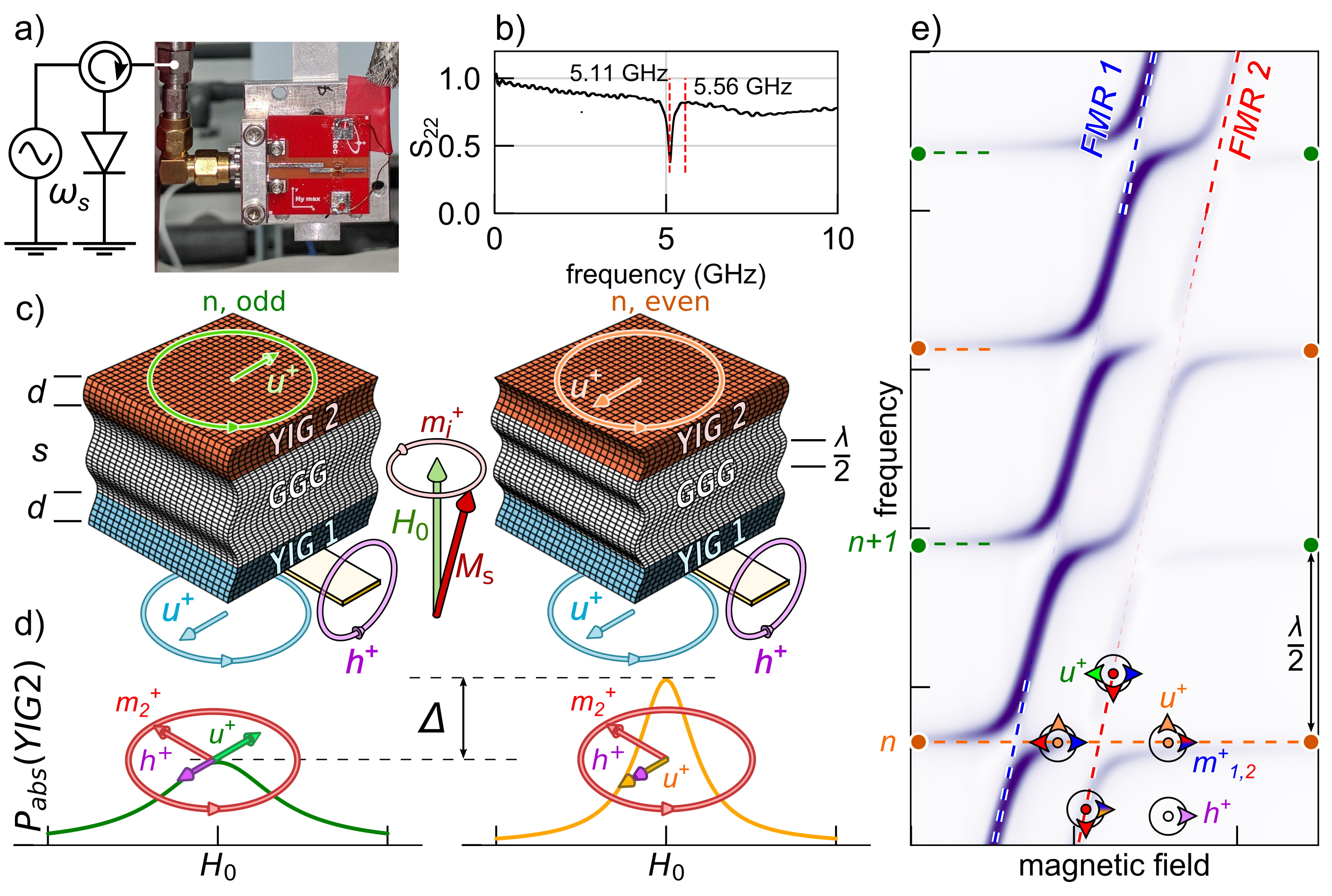
Here we report ferromagnetic resonance experiments (FMR) of a “dielectric spin-valve” stack consisting of half a millimeter thick single-crystal GGG slab coated on both sides by thin YIG films. We demonstrate that GGG can be an excellent conductor of phononic angular momentum currents allowing the coherent coupling between the two magnets over millimeter distance. Figure 1a illustrates the experimental setup in which an inductive antenna monitors the coherent part of the magnetization dynamics. The spectroscopic signature of the dynamic coupling between the two YIG layers is a resonant contrast pattern as a function of microwave frequency (see intensity modulation along FMR2 in Figure 1e).
Before turning to the experimental details, we sketch a simple phenomenological model that captures the dynamics of the fields as described by the continuum model for magneto-elasticity with proper boundary conditions Streib et al. (2018). The perpendicular dynamics of a trilayer with in-plane translational symmetry can be mapped on three coupled harmonic oscillators, viz. the Kittel modes of the two magnetic layers and the -th mechanical mode, , in the dielectric, which obey the coupled set of equations
| (1a) | ||||
| (1b) | ||||
| (1c) | ||||
Here , where is the AW velocity and is a half wavelength that fits into the total sample thickness, with being an integer (mode number). The dynamic quantities are circularly polarized magnetic complex amplitudes ( being the imaginary unit) precessing anti-clockwise around the equilibrium magnetization at Kittel resonance frequencies . In our notation are the magnetic/acoustic relaxation rates Rückriegel et al. (2014) and the constants and are the magneto-elastic interaction and inductive coupling to the antenna, respectively. Coherence effects between and can be monitored by the power as a function of the microwave frequency of the driving field with circular amplitude 111the antenna produces a linear rf field, which decomposes in both a left and right circulating field with only one component coupling to the magnetization dynamics. Note that Eq.(1) holds when the characteristic AW decay length exceeds the film thickness (see below).
The acoustic modes with odd and even symmetry couple with opposite signs, i.e. (see Figure 1c), which affects the dynamics as sketched in Figure 1d. When is odd (even), the top layer returns (absorbs) the power from the electromagnetic field, because the phonon amplitude is out-of(in) phase with the direct excitation, corresponding to destructive (constructive) interference. In other words, the phonons pumped by the dynamics of the layer 1 are reflected vs. absorbed by layer 2. According to Eq.(1), a contrast should emerge between tones separated by half a wavelength. This is illustrated in Figure 1e by plotting the calculated modulation of the magnetic absorption when two Kittel modes with slightly different resonance frequencies and different inductive coupling to the antenna interact via strong coupling to coherent phonons (see below values in Table.(1)). In the figure the effect is more visible around the resonance of the layer with weaker coupling to the antenna (FMR2, red dashed line) since, according to the model, the amplitude of the contrast is proportional to the amplitude ratio of the microwave magnetic fields felt by the two YIG layers: . We employ here a stripline with width ( mm) that couples strongly to the lower layer YIG1, while still allowing to monitor the FMR absorption of YIG2.222We disregard the inhomogeneity in the driving field generated by the local antenna.
Figure 1a is a picture of the bow-tie -resonator (with reflectivity spectrum shown in Figure 1b) with which we perform spectroscopy around GHz. The later fulfills the “half-wave condition” of the phonon relative to the YIG thickness that maximizes the phonon pumping Streib et al. (2018). The sample was grown by liquid phase epitaxy, i.e. by immersing a GGG monocrystal substrate with thickness mm and orientation (111) into molten YIG. The concomitant growth leads to nominally identical YIG layers, with thickness nm on both sides of the GGG. The Gilbert damping parameter , measured as the slope of the frequency dependence of the line width, is evidence for the high crystal quality. All experiments have been carried out at room temperature and on the same sample. Because of that, the results shall be presented in inverse chronological order.
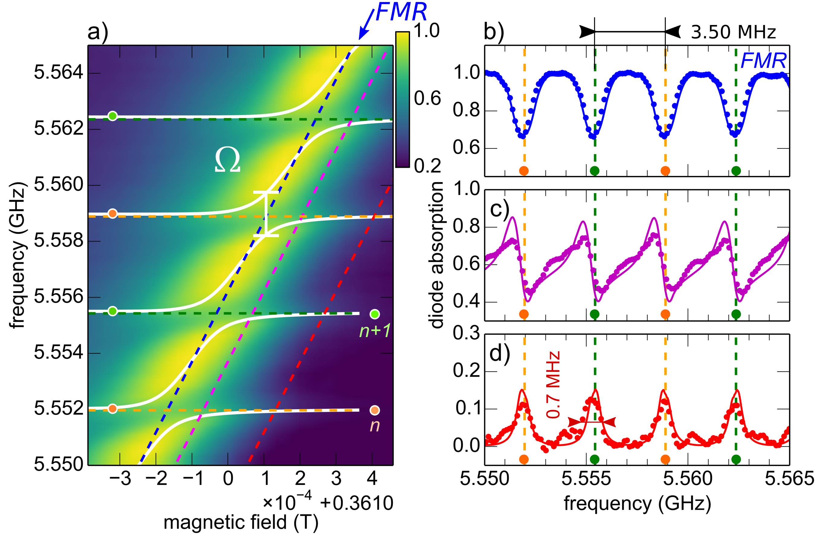
Having removed YIG2 by mechanical polishing, we first concentrate on the dynamic behavior of a single magnetic layer. Figure 2a shows the FMR absorption of YIG1GGG bilayer Gulyaev et al. (1981); Ye et al. (1988); Litvinenko et al. (2015); Tikhonov and Nikitov (2017) around GHz i.e. for a detuned antenna having weak inductive coupling. These spectra are acquired in the perpendicular configuration, where the magnetic precession is circular, by magnetizing the sample with a sufficiently strong external magnetic field, , applied along the normal of the films. Figure 2a provides a detailed view of the fine structure within the FMR absorption that is obtained when one sweeps the field/frequency in tiny steps of 0.01 mT/0.1 MHz, respectively.
The FMR mode (see arrow) follows the Kittel equation 333The exact expression is more complicated and contains cubic/uniaxial anistropies of mT/ mT respectively., with GHz/T, the gyromagnetic ratio and T, the saturation magnetization, but its intensity vs. frequency is periodically modulated Ye et al. (1988); Ye and Dötsch (1991) which we explain by the hybridization with the comb of standing shear AWs described by Eq.(1) truncated to one magnetic layer.
We ascribe the periodicity of 3.50 MHz in the signal of Figures 2 to the equidistant splitting of standing phonon modes governed by the transverse sound velocity of GGG along (111) of m/s Ye et al. (1988); Ye and Dötsch (1991); Khivintsev et al. (2018) via MHz 444the total crystal thickness reduces to after polishing. This value thus separates two phononic tones, which differ by half a wavelength. At 5.5 GHz, the intercept between the transverse AW and SW dispersion relations occurs at cm-1, which corresponds to a phonon wavelength of about nm with index number . The modulation is strong evidence for the high acoustic quality that allows elastic waves to propagate coherently with a decay length exceeding twice the film thickness, i.e. 1 mm. For later reference we point out that the absorption is the same for odd and even phonon modes, whose eigen-values are indicated here by green and orange dots.
In Figures 2bcd we focus on the line shapes at detunings parallel to the FMR resonance as a function of field and frequency indicated by the blue, magenta, and red cuts in Figure 2a. The amplitude of the main resonance (blue line) in Figure 2b dips and the lines broaden at the phonon frequencies Ye et al. (1988); Ye and Dötsch (1991). The minima transform via dispersive-looking signal (magenta in 2ac) into peaks (red 2ad) once sufficiently far from the Kittel resonance as expected from the complex impedance of two detuned resonant circuits, illustrating a constant phase between and along these cuts. The are circularly polarized fields rotating in the gyromagnetic direction, that interact only with acoustic waves with the same polarity, as implemented in Eq. (1) Holanda et al. (2018).
The observed line shapes can be used to extract the lifetime parameters in Eq. (1). We first concentrate on the observed MHz full line width of the acoustic resonances in Figure 2d. Far from the Kittel condition, the absorbed power is governed by the sound attenuation. According to Eq. (1), the absorbed power at large detuning reduces to . The AW decay rate MHz is obtained as the half line width of the acoustic resonance, leading to a characteristic decay length mm for AW excited around 5.5 GHz. The acoustic amplitude therefore decays by over the half millimeter film thickness. The sound amplitude in both magnetic layers are therefore roughly the same, as assumed in Eq.(1). This figure is consistent with the measured ultrasonic attenuation in GGG: 0.70 dB/s at 1GHz Dutoit and Bellavance (1972); Dutoit (1974), i.e., a lifetime of about 0.5 s at 5GHz.
The SW lifetime follows from the broadening of the absorbed power at the Kittel condition which contains a constant inhomogeneous contribution and a frequency-dependent viscous damping term. When plotted as function of frequency, the former is the extrapolation of the line widths to zero frequency, in our case 5.7 MHz (or 0.2 mT). On the other hand, the Gilbert phenomenology (see above) of the homogeneous broadening corresponds to a MHz at 5.5 GHz. The dominantly inhomogeneous broadening is here caused by thickness variations, a spatially dependent magnetic anisotropy, but also by the inhomogeneous microwave field.
Conspicuous features in Figure 2a are the clearly resolved avoided-crossing of SW and AW dispersion relations, which prove the strong coupling between two oscillators. Fitting by hand the dispersions of two coupled oscillators through the data points (white lines), we extract a gap of MHz and a large cooperativity . From the overlap integral between a standing shear AW confined in a layer of thickness and the Kittel mode confined in a layer of thickness , one can derive the analytical expression for the magneto-elastic coupling strength Khymyn et al. (2019); Ye et al. (1988):
| (2) |
where Spencer et al. (1963) J/m3, with and being the magneto-elastic coupling constants for a cubic crystal, and g/cm3 is the mass density of YIG. From Eq.(2) we infer that coherent SW excited around GHz have a dynamic coupling to shear AW of the order of MHz, close to the value extracted from the experiments.
The material parameters extracted for our YIGGGG are summarized in Table (1). Numerical solutions of Eq. (1) using these values are shown as solid lines in Figure 2bcd. The agreement with the data is excellent, confirming the validity of the model and parameters.
| 40 | 3.50 | 1.0 | 0.50 | 0.35 |
|---|
The other needed parameter for solving Eq.(1) in the general case is the attenuation ratio deducted from a factor of 50 decreased power when flipping the single YIG layer sample upside down on the antenna. The layer is then separated 0.5 mm from the antenna, and the observed reduction agrees with numerical simulations using electromagnetic field solvers.
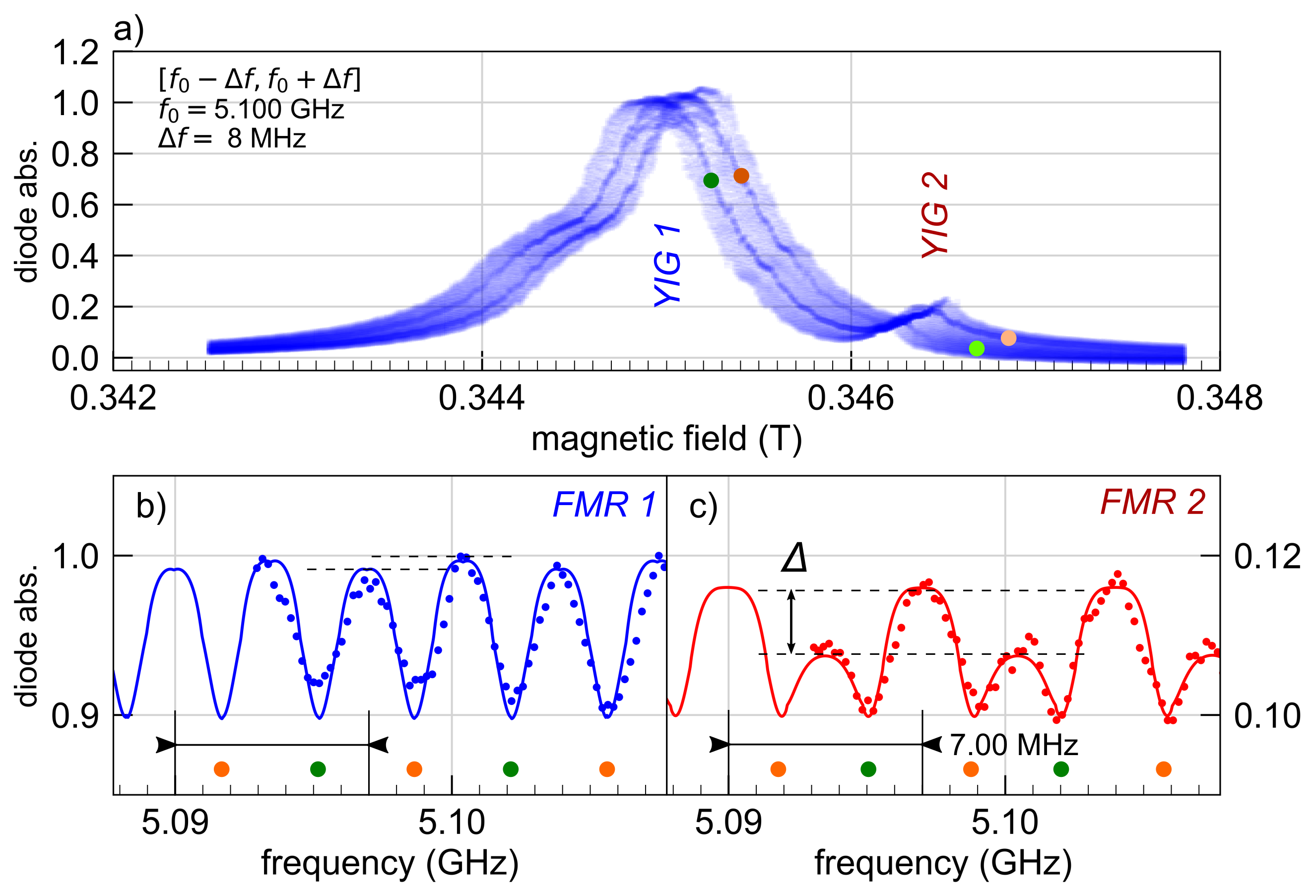
We turn now our attention to the magnetic sandwich in which YIG1 touches the antenna and the nominally identical YIG2 is 0.5 mm away, where a slight difference in uniaxial anisotropy causes separate resonance frequencies. Since we want to detect also the resonance of the top layer, we have to compensate for the decrease in inductive coupling by tuning the source frequency to the antenna resonance at 5.11 GHz (see Figure 1b). This enhances the signal by the quality factor of the cavity at the cost of an increased radiative damping of the bottom layer signal Bloembergen and Pound (1954).
Figure 3a is a transparent overlay of field sweeps for frequency steps of 0.1 MHz in the interval GHz. We attribute the two peaks separated by 1.4 mT (or 40 MHz) to the bottom and top YIG Kittel resonances, the later shifted due to a slight difference in effective magnetization T. Note that the detuning between the two Kittel modes is large compared to the strength of the magneto-elastic coupling . In Figure 3b and Figure 3c we compare the measured modulation of the resonance amplitude for respectively the bottom YIG1 layer and top YIG2 layers. This corresponds to performing 2 cuts at the resonance condition FMR1 and FMR2 in the same fashion as Figure 2b. The top YIG2 signal is modulated with a period of 7.00 MHz (Figure 3c) with a contrast between even and odd modes. This agrees with the prediction of Eq.(1) (see solid lines) due to constructive/destructive couplings mediated by even/odd phonon modes, the modulation period of the absorbed power doubles along the resonance of the top layer (FMR2), when compared to the case of a single YIG layer (Figure 2). Figure 3b illustrates also that the strong coupling to the antenna hinders clear observation of this modulation in the bottom YIG1 layer resonance. Nevertheless, the anticipated sign change of (by the inverted phase of relative to in Eq.(1)) between FMR1 and FMR2 remains observable.
We now address the acoustic resonances revealed by the dark lines in Figure 3a for odd/even indices labeled by green/orange circles in the wings. The phonon line with even index (orange marker) progressively disappears when approaching the YIG2 Kittel resonance from the low field (left side) of the resonance, while the opposite behavior is observed for the odd index feature (green marker), which disappears when approaching the YIG2 Kittel resonance from the high field (right side). This behavior agrees with the model in Figure 1e. The contrast in the acoustic resonance intensity mirrors the contrast of the amplitude of the FMR resonance.
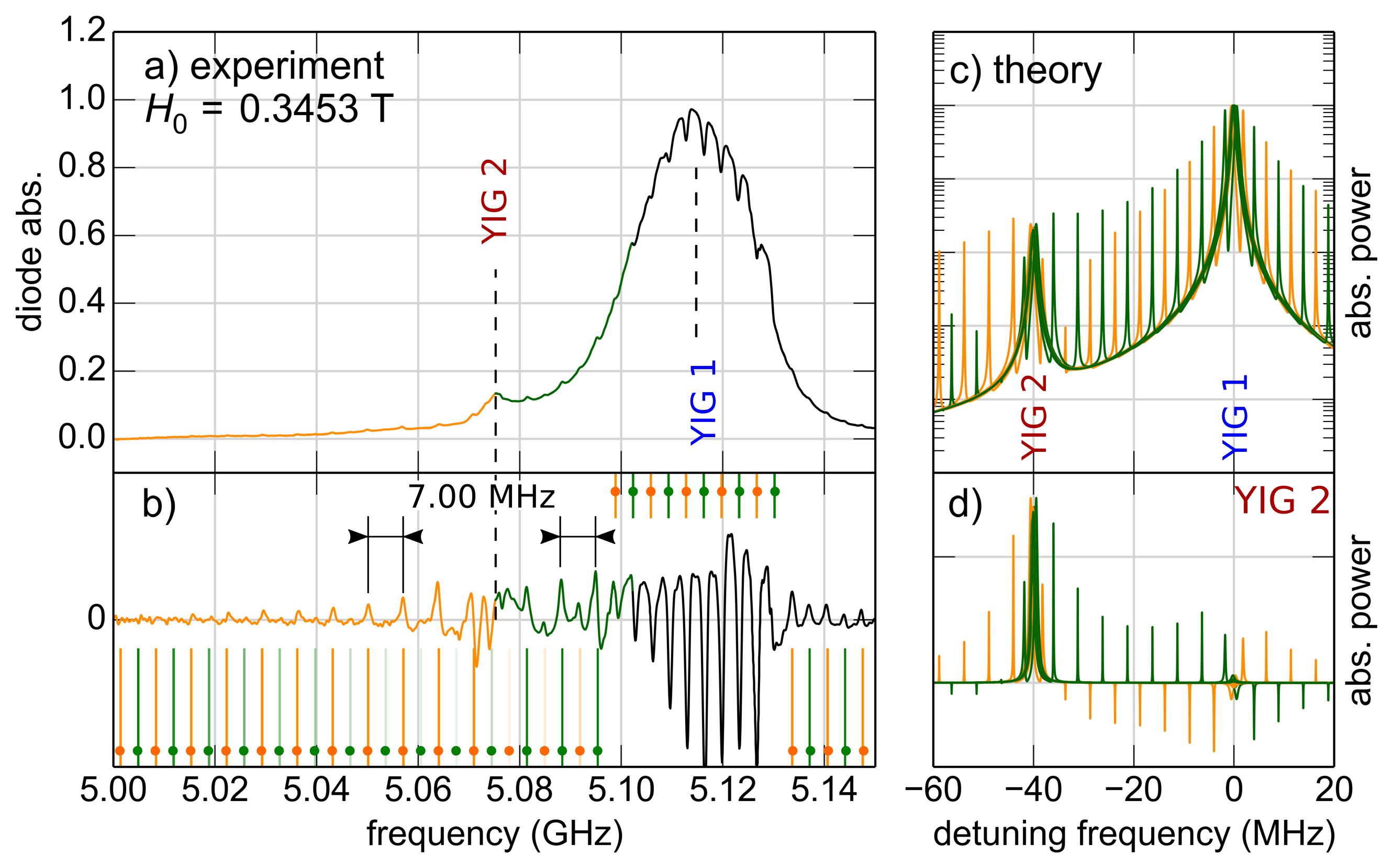
Figure 4a shows the observed FMR absorption spectrum around 5.11 GHz measured at fixed field T. We enhance the fine structure in Figure 4b by subtracting the FMR envelope and progressively amplifying the weak signals in the wings. The orange/green color code emphasizes the constructive/destructive interference of the even/odd acoustic resonances in the top-layer signal. This feature can be explained by Eq. (1), as shown by the calculated curves in Figure 4cd. The acoustic modes change character from even to odd (or vice versa) across the FMR frequency, which is caused by the associated phase shift by 180∘ of the acoustic drive, again explaining the experiments. The absorption by the YIG2 top layer in Figure 4d may even become negative so the phonon current from YIG1 drives the magnetization in YIG2. This establishes both angular momentum and power transfer of microwave radiation via phonons.
In summary, we report interferences between the Kittel resonances of two ferromagnets over macroscopic distance through the exchange of circularly polarized coherent shear waves propagating in a nonmagnetic dielectric. We show that magnets are a source and detector for phononic angular momentum currents and that these currents provide a coupling, analogous to the dynamic coupling in metallic spin valves Heinrich et al. (2003), but with an insulating spacer, over much larger distances, and in the ballistic/coherent rather than diffuse/dissipative regime. This should lead to the creation of a dynamical gap between collective states when the two Kittel resonances are tuned within the strength of the magneto-elastic coupling. Our findings might have implications on the non-local spin transport experiments Cornelissen et al. (2017), in which phonons provide a parallel channel for the transport of angular momentum. While the present experiments are carried out at room temperature and interpreted classically, the high acoustic quality of phonon transport and the strong coupling to the magnetic order in insulators may be useful for quantum communication.
This work was supported in part by the Grants No.18-CE24-0021 from the ANR of France, No. EFMA-1641989 and No. ECCS-1708982 from the NSF of the USA, by the Oakland University Foundation, the NWO and Grants-in-Aid of the Japan Society of the Promotion of Science (Grant 19H006450). V.V.N. acknowledges support from UGA through the invited Prof. program and from the Russian Competitive Growth of KFU. We would like to thank Simon Streib for illuminating discussions.
References
- Bienfait et al. (2019) A. Bienfait, K. J. Satzinger, Y. P. Zhong, H.-S. Chang, M.-H. Chou, C. R. Conner, É. Dumur, J. Grebel, G. A. Peairs, R. G. Povey, and A. N. Cleland, Science 364, 368 (2019).
- Moores et al. (2018) B. A. Moores, L. R. Sletten, J. J. Viennot, and K. Lehnert, Physical Review Letters 120 (2018), 10.1103/physrevlett.120.227701.
- Tsaturyan et al. (2017) Y. Tsaturyan, A. Barg, E. S. Polzik, and A. Schliesser, Nature Nanotechnology 12, 776 (2017).
- Al-Sumaidae et al. (2018) S. Al-Sumaidae, M. H. Bitarafan, C. A. Potts, J. P. Davis, and R. G. DeCorby, Optics Express 26, 11201 (2018).
- Spethmann et al. (2015) N. Spethmann, J. Kohler, S. Schreppler, L. Buchmann, and D. M. Stamper-Kurn, Nature Physics 12, 27 (2015).
- Cornelissen et al. (2015) L. J. Cornelissen, J. Liu, R. A. Duine, J. B. Youssef, and B. J. van Wees, Nat Phys 11, 1022 (2015).
- Oyanagi et al. (2019) K. Oyanagi, S. Takahashi, L. J. Cornelissen, J. Shan, S. Daimon, T. Kikkawa, G. E. W. Bauer, B. J. van Wees, and E. Saitoh, Nature Communications 10 (2019), 10.1038/s41467-019-12749-7.
- Lebrun et al. (2018) R. Lebrun, A. Ross, S. A. Bender, A. Qaiumzadeh, L. Baldrati, J. Cramer, A. Brataas, R. A. Duine, and M. Kläui, Nature 561, 222 (2018).
- Spencer et al. (1959) E. G. Spencer, R. C. LeCraw, and A. M. Clogston, Phys. Rev. Lett. 3, 32 (1959).
- Cherepanov et al. (1993) V. Cherepanov, I. Kolokolov, and V. L’vov, Physics Reports 229, 81 (1993).
- LeCraw and Comstock (1965) R. LeCraw and R. Comstock, in Physical Acoustics vol. 3 (Elsevier, 1965) pp. 127–199.
- Spencer et al. (1962) E. G. Spencer, R. T. Denton, and R. P. Chambers, Physical Review 125, 1950 (1962).
- Kittel (1958) C. Kittel, Physical Review 110, 836 (1958).
- Bömmel and Dransfeld (1959) H. Bömmel and K. Dransfeld, Physical Review Letters 3, 83 (1959).
- Damon and van de Vaart (1965) R. Damon and H. van de Vaart, Proceedings of the IEEE 53, 348 (1965).
- Seavey (1965) M. Seavey, Proceedings of the IEEE 53, 1387 (1965).
- Dreher et al. (2012) L. Dreher, M. Weiler, M. Pernpeintner, H. Huebl, R. Gross, M. S. Brandt, and S. T. B. Goennenwein, Physical Review B 86 (2012), 10.1103/physrevb.86.134415.
- Zhang et al. (2016) X. Zhang, C.-L. Zou, L. Jiang, and H. X. Tang, Science Advances 2, e1501286 (2016).
- Gurevich and Melkov (1996) A. G. Gurevich and G. A. Melkov, Magnetization Oscillations and Waves (CRC Press, 1996).
- Dötsch et al. (1978) H. Dötsch, P. Röschmann, and W. Schilz, Applied Physics 15, 167 (1978).
- Wago et al. (1998) K. Wago, D. Botkin, C. S. Yannoni, and D. Rugar, Applied Physics Letters 72, 2757 (1998).
- Pomerantz (1961) M. Pomerantz, Physical Review Letters 7, 312 (1961).
- Reeder and Winslow (1969) T. Reeder and D. Winslow, IEEE Transactions on Microwave Theory and Techniques 17, 927 (1969).
- Chowdhury et al. (2015) P. Chowdhury, P. Dhagat, and A. Jander, IEEE Transactions on Magnetics 51, 1 (2015).
- Popa and Cummer (2014) B.-I. Popa and S. A. Cummer, Nature Communications 5 (2014), 10.1038/ncomms4398.
- Matthews and LeCraw (1962) H. Matthews and R. C. LeCraw, Physical Review Letters 8, 397 (1962).
- Ogawa et al. (2015) N. Ogawa, W. Koshibae, A. J. Beekman, N. Nagaosa, M. Kubota, M. Kawasaki, and Y. Tokura, Proceedings of the National Academy of Sciences 112, 8977 (2015).
- Hashimoto et al. (2017) Y. Hashimoto, S. Daimon, R. Iguchi, Y. Oikawa, K. Shen, K. Sato, D. Bossini, Y. Tabuchi, T. Satoh, B. Hillebrands, G. E. W. Bauer, T. H. Johansen, A. Kirilyuk, T. Rasing, and E. Saitoh, Nature Communications 8, 15859 (2017).
- Kikkawa et al. (2016) T. Kikkawa, K. Shen, B. Flebus, R. A. Duine, K. ichi Uchida, Z. Qiu, G. E. Bauer, and E. Saitoh, Physical Review Letters 117 (2016), 10.1103/physrevlett.117.207203.
- Holanda et al. (2018) J. Holanda, D. S. Maior, A. Azevedo, and S. M. Rezende, Nature Physics (2018), 10.1038/s41567-018-0079-y.
- Yap et al. (2013) Y. S. Yap, H. Yamamoto, Y. Tabuchi, M. Negoro, A. Kagawa, and M. Kitagawa, Journal of Magnetic Resonance 232, 62 (2013).
- Comstock and LeCraw (1963) R. L. Comstock and R. C. LeCraw, Journal of Applied Physics 34, 3022 (1963).
- Garanin and Chudnovsky (2015) D. A. Garanin and E. M. Chudnovsky, Physical Review B 92 (2015), 10.1103/physrevb.92.024421.
- Streib et al. (2018) S. Streib, H. Keshtgar, and G. E. Bauer, Physical Review Letters 121 (2018), 10.1103/physrevlett.121.027202.
- Spencer et al. (1963) E. G. Spencer, R. T. Denton, T. B. Bateman, W. B. Snow, and L. G. V. Uitert, Journal of Applied Physics 34, 3059 (1963).
- Dutoit and Bellavance (1972) M. Dutoit and D. Bellavance, in 1972 Ultrasonics Symposium (IEEE, 1972).
- Polzikova et al. (2019) N. Polzikova, S. Alekseev, V. Luzanov, and A. Raevskiy, Journal of Magnetism and Magnetic Materials 479, 38 (2019).
- Rückriegel et al. (2014) A. Rückriegel, P. Kopietz, D. A. Bozhko, A. A. Serga, and B. Hillebrands, Physical Review B 89 (2014), 10.1103/physrevb.89.184413.
- Note (1) The antenna produces a linear rf field, which decomposes in both a left and right circulating field with only one component coupling to the magnetization dynamics.
- Note (2) We disregard the inhomogeneity in the driving field generated by the local antenna.
- Gulyaev et al. (1981) Y. V. Gulyaev, P. E. Zil’berman, G. T. Kazakov, V. G. Sysoev, V. V. Tikhonov, Y. A. Filimonov, B. P. Nam, and A. S. Khe, JETP Lett. 34, 500 (1981).
- Ye et al. (1988) M. Ye, A. Brockmeyer, P. E. Wigen, and H. Dötsch, Le Journal de Physique Colloques 49, C8 (1988).
- Litvinenko et al. (2015) A. N. Litvinenko, A. V. Sadovnikov, V. V. Tikhonov, and S. A. Nikitov, IEEE Magnetics Letters 6, 1 (2015).
- Tikhonov and Nikitov (2017) V. V. Tikhonov and S. A. Nikitov, Bulletin of the Russian Academy of Sciences: Physics 81, 969 (2017).
- Note (3) The exact expression is more complicated and contains cubic/uniaxial anistropies of mT/ mT respectively.
- Ye and Dötsch (1991) M. Ye and H. Dötsch, Physical Review B 44, 9458 (1991).
- Khivintsev et al. (2018) Y. V. Khivintsev, V. K. Sakharov, S. L. Vysotskii, Y. A. Filimonov, A. I. Stognii, and S. A. Nikitov, Technical Physics 63, 1029 (2018).
- Note (4) The total crystal thickness reduces to after polishing.
- Dutoit (1974) M. Dutoit, Journal of Applied Physics 45, 2836 (1974).
- Khymyn et al. (2019) R. S. Khymyn, V. S. Tiberkevich, and A. N. Slavin, to be published (2019).
- Bloembergen and Pound (1954) N. Bloembergen and R. V. Pound, Physical Review 95, 8 (1954).
- Heinrich et al. (2003) B. Heinrich, Y. Tserkovnyak, G. Woltersdorf, A. Brataas, R. Urban, and G. E. W. Bauer, Physical Review Letters 90, 187601 (2003).
- Cornelissen et al. (2017) L. J. Cornelissen, K. Oyanagi, T. Kikkawa, Z. Qiu, T. Kuschel, G. E. W. Bauer, B. J. van Wees, and E. Saitoh, Physical Review B 96 (2017), 10.1103/physrevb.96.104441.