Precise Mirror Alignment and Basic Performance of the RICH Detector of the NA62 Experiment at CERN
Abstract
The Ring Imaging Cherenkov detector is crucial for the identification of charged particles in the NA62 experiment at the CERN SPS. The detector commissioning was completed in 2016 by the precise alignment of mirrors using reconstructed tracks. The alignment procedure and measurement of the basic performance are described. Ring radius resolution, ring centre resolution, single hit resolution and mean number of hits per ring are evaluated for positron tracks. The contribution of the residual mirror misalignment to the performance is calculated.
1 Introduction
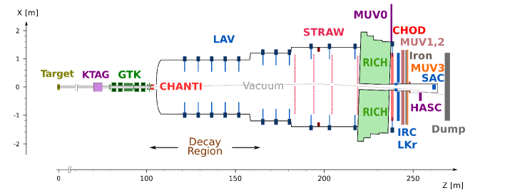
The NA62 experiment at CERN is aimed at measuring the ultra rare decay (BR10-10). The BR measurement with 10 precision will allow to probe New Physics at mass scales up to O(100) TeV. The experimental setup is shown in figure 1 and described in detail in [1]. A 400 GeV/c proton beam from the CERN SPS impinging on a Beryllium target produces a 750 MHz hadron beam of 75 GeV/c with 6 of K+ particles. Kaons are identified by the KTAG detector, a differential Cherenkov counter. The momentum of beam particles is measured by the beam tracker (GTK). The momentum of secondary particles is measured by a magnetic spectrometer with Straw chambers (STRAW) operating in vacuum. The system of hodoscope counters (CHOD) consisting of scintillator slabs and tiles measures the track crossing time and contributes to the L0 trigger, as well as the Ring Imaging CHerenkov detector (RICH). The iron/scintillator calorimeters (MUV1,2) identify pions and muons, while the electron/positron identification (ID) is performed by the electromagnetic calorimeter filled with Liquid Krypton (LKr). A fast muon veto (MUV3) identifies muons and provides L0 trigger signals. The photon veto system covers the angular range up to 50 mrad and includes four detectors: LAV, LKr, IRC and SAC. The CHANTI detector placed after the third station of GTK identifies upstream inelastic interactions and muon halo. Additional veto detectors MUV0 and HASC are used to detect pions from the decay escaping from the STRAW acceptance.
2 RICH detector
One of the main backgrounds to the decay comes from which is suppressed by applying specific selection criteria on kinematic variables and making use of the different stopping power of muons and pions in MUV1 and MUV2. The RICH detector is needed to further reject the muon contamination in the pion sample by a factor of at least 100 in the momentum range between 15 and 35 GeV/c. The upper bound of this range is driven by the kinematic suppression of the other principal background, the (K2) decay. To distinguish between muons and pions at 35 GeV/c, the RICH should have a Cherenkov threshold for pions around 12–13 GeV/c which means that the full efficiency of the RICH is achieved at 15 GeV/c. The choice of this lower bound is also favoured by studies of other backgrounds.
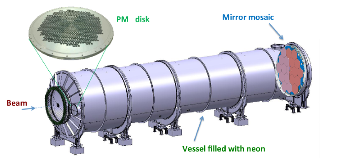
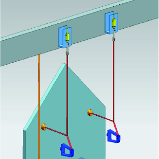
The RICH detector is shown in figure 2. The core part of the detector is the mirror system [2]. It consists of 18 hexagonal (350 mm side) and two semi-hexagonal mirrors which are placed in the central part and cut to accomodate the beam pipe. The focal length of all mirrors is =17 m. The mirror orientation is provided by two stabilizing aluminium ribbons connected to the mirror at one end (at a distance of 250 mm from the barycentre) and to a piezo motor at the other end via the transmission tool. A third anti-rotating ribbon prevents the mirror rotation around the longitudinal axis. The ribbon arrangement is shown in figure 3. Piezo motors move ribbons with 1 nm step.
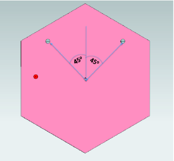
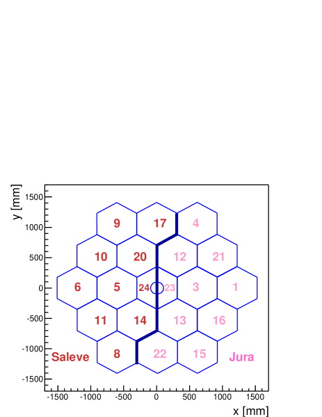
To avoid the loss of the reflected light interacting with the beam pipe, the mirrors are divided in two groups referred to as Jura and Saleve with centres of curvature of mirror surface, respectively, to the right and to the left of the beam pipe, as seen from the downstream part of the setup. Figure 4 illustrates the mirror numbering and Jura–Saleve orientation. The Jura group is shown in light pink, the Saleve one is in dark pink, the same colors are used in figure 2.
Two photomultiplier (PM) disks are placed in the focal plane of each mirror orientation group and are located at about 1.5 m to the left and to the right of the beam pipe, outside the area illuminated by charged particles from kaon decays in the fiducial volume. Each disk contains 976 PMs. The PM disk diameter is 600 mm. To enhance light collection, Winston cones [3] with the outer diameter dcone=18 mm are carved in the disks and covered with aluminized Mylar (one cone per PM). The inner diameter of Winston cones is equal to the diameter of the PM sensitive area dPM=7.5 mm.
3 Precise mirror alignment
3.1 Alignment procedure
The best performance of the RICH detector is achieved when the mirrors are aligned with the highest possible precision. During the installation a preliminary laser alignment was performed for each mirror with the accuracy of 500 rad in terms of mirror orientation [2]. For a more precise alignment using reconstructed tracks a dedicated procedure has been developed. For each orientation group (Jura or Saleve, see figure 4) a reference mirror was chosen and all other mirrors were aligned with respect to that mirror. A natural choice for the reference mirror is a semihexagonal one, for which the remotely controlled rotation is limited to one degree of freedom, i.e. only one ribbon can be moved using piezo motors.
The fine alignment procedure consists of three steps. It starts from the measurement of the absolute misalignment (i.e. with respect to the nominal orientation) of all 20 mirrors. Events with one track in the STRAW and one RICH ring candidate are selected for the analysis. The RICH ring is required to be completely within the PM acceptance. A circle at the mirror plane centered on the track impact point and having the same radius as the ring is required to be within a single mirror (“single mirror “ condition). The absolute misalignment of a mirror is the mean value of the difference between the real ring centre position from the ring fit and the expected position. The latter corresponds to the nominal mirror orientation and is obtained by extrapolating the track to the PM plane as if it were a photon with the direction of the track reflected by a mirror with the nominal centre of curvature.
At the second step, the relative misalignment of each hexagonal mirror is calculated. The relative misalignment is defined as the difference in the absolute misalignment between a mirror and the reference mirror of a corresponding group. Using a simple model with the ideal ribbon geometry [2], it is linearly translated to the piezo motor movement needed to compensate the relative misalignment:
| (3.1) |
Here and are the relative misalignment values, and are the movements of piezo motors L and R needed to compensate this misalignment, is the distance between the ribbon connection point to the mirror and the mirror barycentre (for the definition of L, R and see figure 3), is the mirror focal length. Each mirror is rotated by moving two piezo motors according to the calculated values and . After the first movement the misalignment is measured again, and the change in the relative misalignment is translated back to the effective movement of piezo motors and (i.e. the piezo motor movement which would produce that change in the misalignment in case of the ideal ribbon geometry). For each piezo motor a calibration constant is calculated by comparing the effective and real movement: c for a left motor, c for a right one. Further piezo movements are performed taking into account these constants, i.e. and calculated from (3.1) are multiplied by cL and cR respectively.
The final step of the procedure is the calculation of global offsets and the residual misalignment. A global offset is the average absolute misalignment of a group of mirrors with the same centre of curvature (Jura or Saleve). To calculate a global offset, events with hits in a single PM disk (and hence only one group of mirrors illuminated) are selected (“single mirror “ condition is not applied), and the absolute misalignment is measured. The difference between the absolute misalignment of a mirror and the global offset is referred to as the residual misalignment.
For rings with photons from a single group of mirrors the performance does not depend on how the global offset of that group is defined, while for rings where mirrors of both groups are illuminated such definition of global offsets provides the minimal average spread of hit coordinates due to the residual misalignment and hence the best single hit resolution. A simpler alternative could be to define a global offset as the absolute misalignment of the reference mirror (the residual misalignment in this case would be equal to the relative one), but in this case the best performance will be achieved only for rings with hits from reference semihexagonal mirrors, while for rings with hits from hexagonal Jura and Saleve mirrors (for example, 13–14 or 12–20 in figure 4) a larger relative misalignment will take place, that will result in a worse single hit resolution.
The procedure of piezo motor movement is repeated iteratively until the final accuracy is achieved: 1 mm in terms of the relative misalignment, or 30 rad in terms of the mirror angular orientation. The latter number comes from the relation , where is the mirror rotation, r is the corresponding movement of the ring centre in the focal plane and m is the mirror focal length. At each iteration step the global offsets calculated at the previous step are used as initial global offsets.
Global offsets and residual misalignment values are stored in a metadata file and used in the analysis chain. At the RICH reconstruction level (when only the RICH hits are used, no track information is available) global offsets are subtracted from hit coordinates before the standalone ring fit is performed. At the analysis level the ring fit can be improved by using the track information. In this case the absolute misalignment (i.e. the sum of the global offset and the residual misalignment) of the track-pointed mirror is subtracted from the hit coordinates before the track-seeded ring fit. Such offset subtraction is driven by the fact that the main part of photons is reflected by the mirror where the track points. This can be easily obtained from geometrical considerations assuming a uniform spatial density of photons in the mirror plane. Moreover, due to the properties of the Cherenkov radiation (dN/dz=const and hence dN/dr=const, where r is the radial coordinate with respect to the track impact point of a photon emitted at z) this density is proportional to 1/r, which leads to even higher photon concentration around the impact point.
3.2 Alignment in 2016
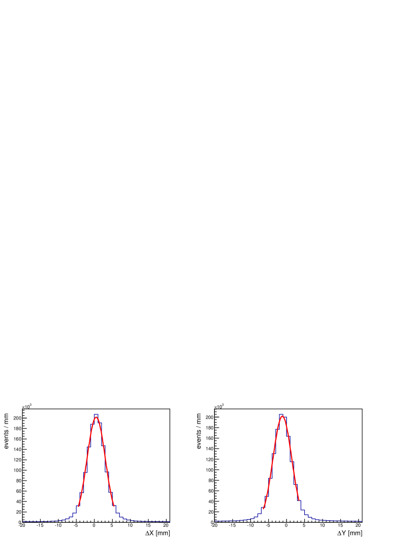
In 2016 the alignment procedure was fully accomplished for the first time. A typical measurement of the absolute misalignment is shown in figure 5. The accuracy of the misalignment measurement is estimated to be 0.1 mm, the main contribution coming from the fitting procedure. Two contributions determine the width of the X and Y distribution: the uncertainty of ring centre and spectrometer resolution. The latter is small and can be estimated by multiplying the mirror focal length by the STRAW angular resolution or . In the assumption that , where the value is taken from [1], the spectrometer contribution to the widths does not exceed 0.6 mm.
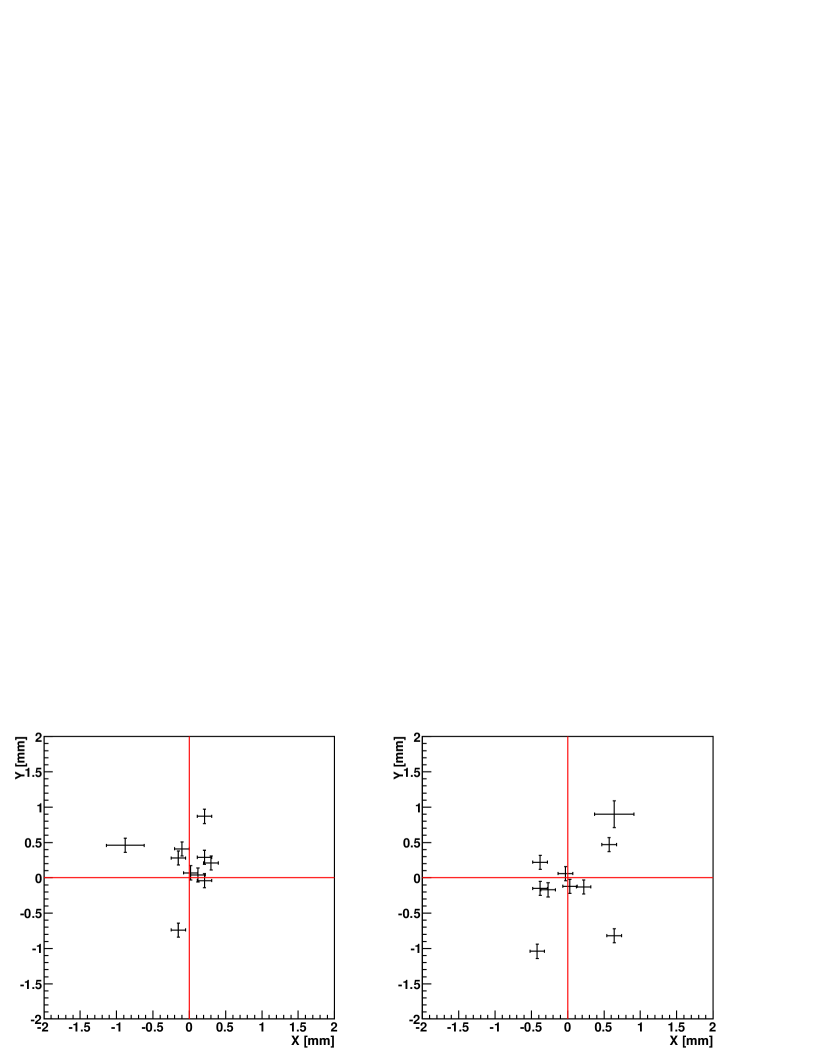
The global offsets (Xglobal, Yglobal) at the end of the alignment procedure were equal to (20.0, 20.1) mm for Jura and (20.1, 9.5) mm for Saleve. The final results of the residual misalignment measurement are shown in figure 6. The precision of the overall procedure is 1 mm and is limited by hysteresis effects in the ribbon-mirror system: for small movements there is no longer linearity between piezo motor and ring centre movement, so the iterative procedure does not necessarily converge. The values of the residual misalignment are given in appendix (table 2).
In 2017 the mirror alignment was monitored on a monthly basis and remained stable during the data taking period.
4 Basic performance in 2016
The RICH detector was designed to provide the muon suppression at the level of O(100) in the pion sample and measure the downstream time with O(100) ps precision. The corresponding performance characteristics (i.e. pion ID efficiency, muon mis-ID probability, event time resolution) depend on the event selection and their measurement is beyond the scope of this paper. The preliminary results are reported in [1]. Apart from the event selection, these characteristics are determined by more fundamental performance parameters like single hit resolution and the average number of hits per event which are traditionally evaluated for electron/positron tracks in order to avoid the momentum dependence.
In this section the measurement of the basic performance of the RICH detector is described which has been performed on rings fully contained in the detector acceptance (to avoid edge effects) and includes the following parameters: ring radius resolution, ring centre resolution, single hit resolution and mean number of hits per ring.
4.1 Event selection
The positron sample has been collected by the tight selection of the (Ke3) decay events. The selection criteria can be grouped into four categories: one track selection, particle ID, kinematics and RICH selection.
The one track selection requires one track events with a track including hits from all chambers and lying in the acceptance of each STRAW station, LKr, CHOD and MUV3. Other track requirements are: time within 10 ns from the trigger time, less than 20, momentum between 12 and 40 GeV/c.
The positron ID is based on the information from calorimeters and contains the following requirements: track is associated with LKr with E/p between 0.96 and 1.03, there are no hits in MUV3 associated with the track.
The kinematics of the Ke3 decay is used to further clean the sample. The kaon is identified by a KTAG candidate close in time with the trigger: ns. Each kaon is assigned the average momentum obtained from a sample of fully reconstructed K decays, instead of the value measured by the GTK, since the GTK performance was not optimal in 2016. The kaon and positron tracks are required to form a vertex with m and 25 mm, where dmin is the minimal distance between the tracks. The neutral pion is reconstructed from two clusters in LKr not associated with the track, with no signal in photon veto detectors (LAV, IRC, SAC). The missing mass squared, assuming the positron hypothesis for the track, is requested to be close to 0: 0.01 GeV2/c4. To reject the residual background from the K2 decay, the missing mass squared, assuming the pion hypothesis, is required to be outside the interval (0, 0.04) GeV2/c4.
Finally, the RICH selection is performed to have a sample of single ring events. The number of hits per ring is requested to be greater than three. The ring is required to lie within PM acceptance. A corresponding circle at the mirror plane, constructed as explained in section 3.1, is requested to be within the mirror acceptance. Also, to avoid possible light loss, the selection contains the requirement for Cherenkov cones not to have intersection with the beam pipe (the latter condition is checked for the largest cone corresponding to the most upstream light emission point).
To precisely measure the ring parameters and correctly calculate the number of hits, a standalone iterative single ring fit algorithm has been developed. At each step a standard single ring fit is performed: the sum is minimized, where is the distance between the i-th hit position and the ring centre, R is the ring radius, =4.7 mm is the single hit resolution (see section 4.4). After the ring fit, a special is calculated for each hit: . Here ti is the i-th hit time, is the average hit time, =0.28 ns is the hit time resolution. The hit with the largest (iter) is removed and the ring fit is repeated unless one of the following conditions is satisfied:
-
•
(iter) < 16 for each hit;
-
•
N5;
-
•
Nhits=4.
The iterative procedure allows to effectively remove noise hits that are far from the main bulk of hits in space and/or time. On average, 0.8 hits per event are rejected.
4.2 Ring radius resolution

The ring radius distribution is shown in figure 7. The ring resolution is obtained from the gaussian width of the distribution.
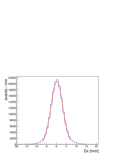
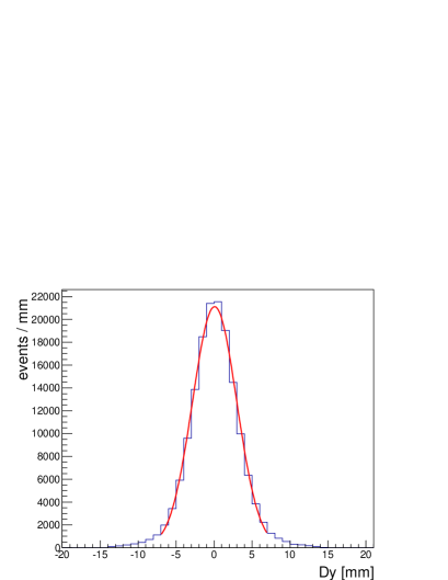
4.3 Ring centre resolution
To estimate the ring centre resolution, the difference between the measured and expected ring centre position (in X and Y) is plotted and fitted by a gaussian, see figure 8. The uncertainty of the expected ring centre position is determined by the STRAW angular resolution (see 3.2) and is much smaller than the measured widths 3 mm, hence and are used to estimate the ring centre resolution.
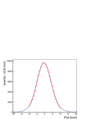
4.4 Single hit resolution
The single hit resolution is estimated from the gaussian width of the pull distribution. The pull is defined as follows: Pull = (R - Rexp). Here R is the ring radius, Rexp is the radius calculated from the momentum assuming the positron mass, (Nhits-3) is the number of degrees of freedom of the single ring fit, where 3 is the number of fit parameters (ring radius and two ring centre coordinates). The pull distribution is shown in figure 9; the obtained value is =4.66 mm.
The main contribution to the single hit resolution comes from the geometry, i.e. from the size of outer and inner Winston cone diameter. In case of the full light collection by the cone the geometry contribution is equal to mm. In the opposite case (absorbing cone surface) it is determined by the diameter of the sensitive region of PMs: mm. The mean cone reflectivity is estimated by averaging the Mylar reflectivity over the real photon spectrum. This spectrum is obtained taking into account all possible effects: the emission spectrum of Cherenkov photons, mirror reflectivity, transmission of quartz windows located between cones and PMs, PM quantum efficiency. A simple simulation of the hit coordinate spread, taking into account the calculated mean reflectivity and assuming not more than one reflection per photon on the cone with the nominal diameter , gives the following estimate: 4.45 mm.
The second contribution comes from the mirror misalignment and is calculated from the quadratic difference between the single hit resolution measured on a standard and “single mirror “ selection (see section 4.6): =2.1 mm.
The contribution due to the neon dispersion [4] can be calculated from the standard deviation of (n-1): , where is the Cherenkov angle, . The value of is obtained by averaging (n-1) and (n-1)2 over the real photon spectrum. With , this results in 0.6 mm which is small compared to other contributions.
By quadratically subtracting and from the measured value , the real geometry contribution can be extracted: 4.14 mm which is smaller than . It could be due to light losses in multiple reflections of photons that are incident on the cone periphery, as described in [3].
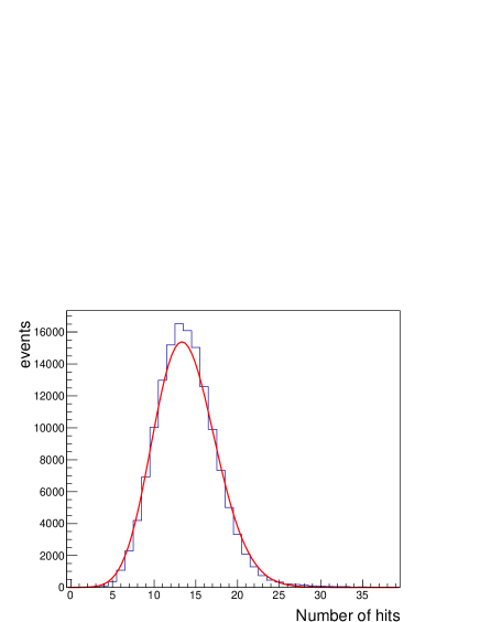
4.5 Number of hits per ring and figure of merit
The distribution of the number of hits per ring is shown in figure 10. From the average value of <Nhits> one can calculate the figure of merit N0 used to evaluate the performance of RICH detectors: N, where L is the vessel length and is the Cherenkov angle. The obtained value is N65 cm-1.
4.6 Contribution of the residual mirror misalignment to the performance
To estimate the contribution of the residual misalignment to the resolutions of ring parameters, the parameter calculation is repeated for the events where all the light comes from a single mirror. The contribution due to the mirror misalignment is given by the quadratic difference between the initial and single mirror value.
Table 1 summarizes the performance measurements and the contributions due to the residual mirror misalignment.
| Parameter | all events | single mirror events | misalignment contribution |
|---|---|---|---|
| <R>, mm | 189.6 | 189.1 | – |
| , mm | 1.47 | 1.31 | 0.7 |
| , mm | 2.96 | 2.82 | – |
| , mm | 2.92 | 2.83 | – |
| , mm | 4.66 | 4.18 | 2.1 |
| <Nhits> | 13.8 | 14.1 | – |
A higher <Nhits> value for single mirror events is due to the fact that in this case the mirror edges with worse reflectivity are not illuminated.
5 Conclusion
The procedure of the precise RICH mirror alignment has been developed and successfully accomplished in 2016. The achieved residual misalignment is 1 mm in terms of the ring centre position (30 rad in terms of the mirror angular orientation).
The basic performance parameters have been measured for positron tracks. The ring radius resolution is 1.5 mm, the ring centre resolution is 3.0 (2.9) mm for X (Y) coordinate, the single hit resolution is 4.7 mm, the average number of hits per ring is 13.8. The contribution of the residual mirror misalignment to the single hit resolution is 2.1 mm and less than 1 mm to the ring radius resolution.
Acknowledgments
The authors are grateful to the staff of the CERN laboratory and the technical staff of participating universities and laboratories for their valuable help during the mirror alignment procedure. The present work was completed thanks to the dedication of the whole NA62 Collaboration in operating the experiment in data-taking conditions and later in providing results from the off-line data processing.
Appendix A Residual misalignment of all mirrors
In this appendix the residual misalignment of all mirrors at the end of the alignment procedure is summarized in a table.
| Mirror | Group | X, mm | X, mm | Y, mm | Y, mm |
|---|---|---|---|---|---|
| 1 | Jura | -0.9 | 0.3 | 0.5 | 0.1 |
| 3 | Jura | 0.2 | 0.1 | 0.9 | 0.1 |
| 4 | Jura | 0.1 | 0.1 | 0.0 | 0.1 |
| 5 | Saleve | 0.6 | 0.1 | -0.8 | 0.1 |
| 6 | Saleve | -0.4 | 0.1 | -1.0 | 0.1 |
| 8 | Saleve | 0.0 | 0.1 | -0.1 | 0.1 |
| 9 | Saleve | -0.4 | 0.1 | -0.1 | 0.1 |
| 10 | Saleve | -0.3 | 0.1 | -0.2 | 0.1 |
| 11 | Saleve | 0.0 | 0.1 | 0.1 | 0.1 |
| 12 | Jura | 0.2 | 0.1 | 0.0 | 0.1 |
| 13 | Jura | -0.1 | 0.1 | 0.3 | 0.1 |
| 14 | Saleve | 0.6 | 0.1 | 0.5 | 0.1 |
| 15 | Jura | 0.2 | 0.1 | 0.3 | 0.1 |
| 16 | Jura | 0.3 | 0.1 | 0.2 | 0.1 |
| 17 | Saleve | -0.4 | 0.1 | 0.2 | 0.1 |
| 20 | Saleve | 0.2 | 0.1 | -0.1 | 0.1 |
| 21 | Jura | -0.1 | 0.1 | -0.7 | 0.1 |
| 22 | Jura | 0.0 | 0.1 | 0.1 | 0.1 |
| 23 | Jura | -0.1 | 0.1 | 0.4 | 0.1 |
| 24 | Saleve | 0.6 | 0.3 | 0.9 | 0.2 |
References
- [1] NA62 Collaboration, E. Cortina Gil et al., The Beam and detector of the NA62 experiment at CERN, 2017 JINST 12 P05025 [arXiv:1703.08501].
- [2] D. Aisa et al, Mirror system of the RICH detector of the NA62 experiment, 2017 JINST 12 P12017.
- [3] H. Hinterberger and R. Winston, Efficient light coupler for threshold Cherenkov counters, Rev. Sci. Instrum. 37 (1966) 1094.
- [4] A. Bideau-Mehu et al, Measurement of the refractive indices of neon, argon, krypton and xenon in the 253.7–140.4 nm wavelength range. Dipsersion relations and estimated oscillator strengths of the resonance lines, J. Quant. Spectrosc. Radiat. Transfer 25 (1981) 395.