Tunable High Gradient Quadrupoles For A Laser Plasma Acceleration Based FEL11footnotemark: 1
Abstract
Laser Plasma Acceleration (LPA) is capable of producing a GeV beam within a cm accelerating distance, but with a rather high initial divergence and large energy spread. COXINEL aims to demonstrate a compact Free Electron Laser using such a source, where a specific transport line with adequate elements is used, such as tunable high gradient quadrupoles for handling the divergence. An innovative permanent magnet based quadrupole (QUAPEVA) made of two quadrupoles superimposed capable of generating a gradient of 200 T/m is presented. The first quadrupole consists of magnets shaped as a ring and attaining a constant gradient of 155 T/m, and the second one made of four cylindrical magnets surrounding the ring and capable of rotating around their axis to achieve a gradient tunability of 46 T/m. Each tuning magnet is connected to a motor and controlled independently, enabling the gradient to be tuned with a rather good magnetic center stability (10 m) and without any field asymmetry. The measurements and field optimization of seven quadrupoles with different magnetic lengths are reported. A set of QUAPEVA triplet, installed at COXINEL, achieved good focusing and enabled beam based alignment.
keywords:
Permanent magnet, quadrupoleMSC:
[2010] 00-01, 99-001 Introduction
Laser Plasma Acceleration (LPA) performance has exceeded that of conventional RF accelerators regarding accelerating distance[1, 2]. It can now generate several GeV beam within a very short accelerating distance (few centimeters), high peak current 10 kA and short bunch duration (few fs), however the divergence is quite large (few mrads) as well as the energy spread (few percent). Thus this application has a requirement of quadrupoles with gradient up to 200 T/m to handle such a beam. With the use of permanent magnet technology, one is able to reduce the bore aperture of the quadrupole and thus attain a larger gradient. Permanent Magnet Quadrupoles (PMQs) achieve gradients of the order of hundreds T/m with compactness, and also with the absence of power supplies makes them a solution for future sustainable green society.
Several Halbach [3] ring based PMQs with fixed gradient were designed and built: at CESR [4]; at Kyoto University / SLAC [5]; at CORNELL [6]; at the department fr Physik [7]; at ESRF [8]. As for introducing gradient tunability in PMQs, original designs were proposed and developed to provide a variable gradient, such as at SLAC / Fermilab collaboration [9]; at Kyoto U. / SLAC collaboration [10]; at STFC Daresbury Laboratory / CERN for the CLIC project [11].
In this paper, a hybrid permanent magnet based quadrupole with tunable gradient (QUAPEVA) developed at Synchrotron SOLEIL in collaboration with SIGMAPHI is presented. Its design provides a high tunable gradient strength 156 46 T/m and small magnetic center excursions within 10 in both transverse planes. Seven systems have been built with different magnetic lengths, a first set of triplet (26 mm, 40.7 mm, 44.7 mm), a second triplet (47.1 mm, 61 mm, 81.1 mm), and a prototype (100 mm). Simulation models are presented alongside the mechanical design. Different magnetic measurements are used to characterize the field quality and are compared with the simulation models. Finally, three QUAPEVAs have been used for the COXINEL project [12, 13].
2 Magnetic Design
The QUAPEVA consists of two superimposed quadrupoles, where the first quadrupole placed in the center is a Halbach hybrid ring with a fixed gradient surrounded by a second one composed of four cylindrical magnets capable of rotating around their axis providing the gradient tunability. The geometry and magnetic characteristics of the QUAPEVA are optimized using two numerical tools: RADIA [14] a magnetostatic code based on boundary integral method(see Fig. 1-a) and TOSCA [15] a finite element magnetostatic code (see Fig. 1-b). The magnet and pole characteristics are shown in Table 1.
| Parameter | Value | Unit |
|---|---|---|
| Remanent Field | 1.26 | T |
| Coercivity | 1830 | kA/m |
| Pole saturation | 2.35 | T |
| Radius for Good Field Region (GFR) | 4 | mm |
| at GFR |
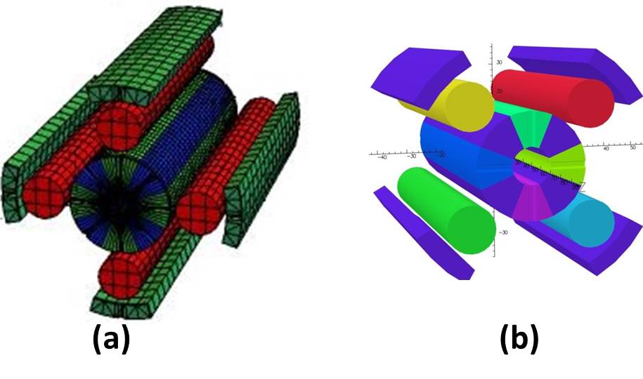
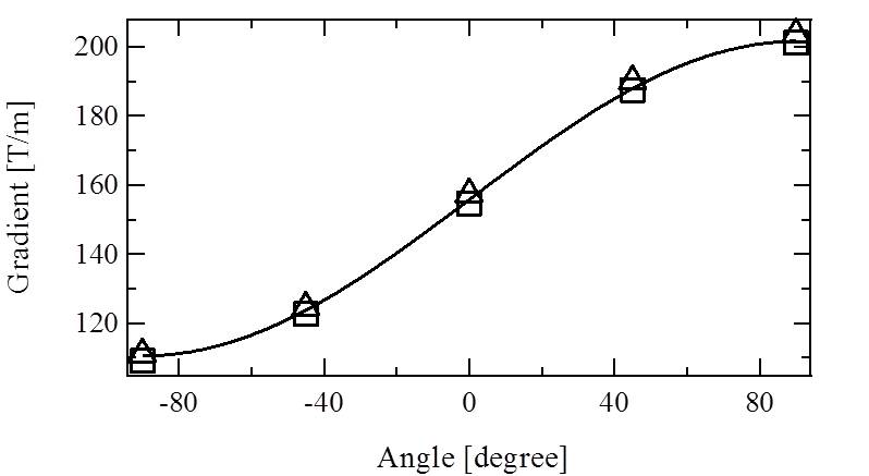
Fig. 2 shows the simulated gradient evolution with tuning magnet angle in the case of the prototype, where the gradient reaches a maximum and a minimum value between -90 and +90 degrees. Simulation results of RADIA and TOSCA models are in good agreement. The evolution is fitted with a sinus function , where is the gradient contribution of the main magnets (tuning magnets are in their reference position), the gradient contribution of all the tuning magnets, and their corresponding angle. In the case of the prototype (100 mm magnetic length), =155 T/m and =46 T/m are found. The gradient variation from peak to peak is 92 T/m and the maximum gradient reached is 201 T/m. The maximum gradient and tunability of each system are shown in Table. 2.
| Magnetic length | [T/m] | [T/m] |
|---|---|---|
| 100 mm | 201 | 92 |
| 81.1 mm | 195 | 89 |
| 61 mm | 190 | 88 |
| 47.1 mm | 184 | 86 |
| 44.7 mm | 183 | 86 |
| 40.7 mm | 180 | 85 |
| 26 mm | 164 | 78 |
3 Mechanical Design
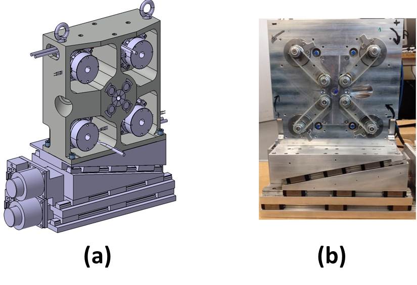
The quadrupole is supported by a translation table to compensate for the residual shift of the magnetic center in both transverse planes as the gradient is varied, and is built into an Aluminum support frame to maintain the magnetic elements in their positions. Each cylindrical magnet is connected to one motor preventing a break of symmetry whilst changing the gradient. The motors are placed at the corners to avoid perturbations of the magnetic field, and are connected to the cylindrical magnets by non-magnetic belts that transmit the rotation movement. The chosen motors (HARMONIC DRIVE, FHA-C mini motors) have sufficient torque to counteract the magnetic forces, are very compact (48.5 x 50 x 50 mm3), and have an encoder of 31 resolution. Fig. 3 presents the mechanical design (a) along side an assembled QUAPEVA (b).
4 Magnetic measurements of QUAPEVA
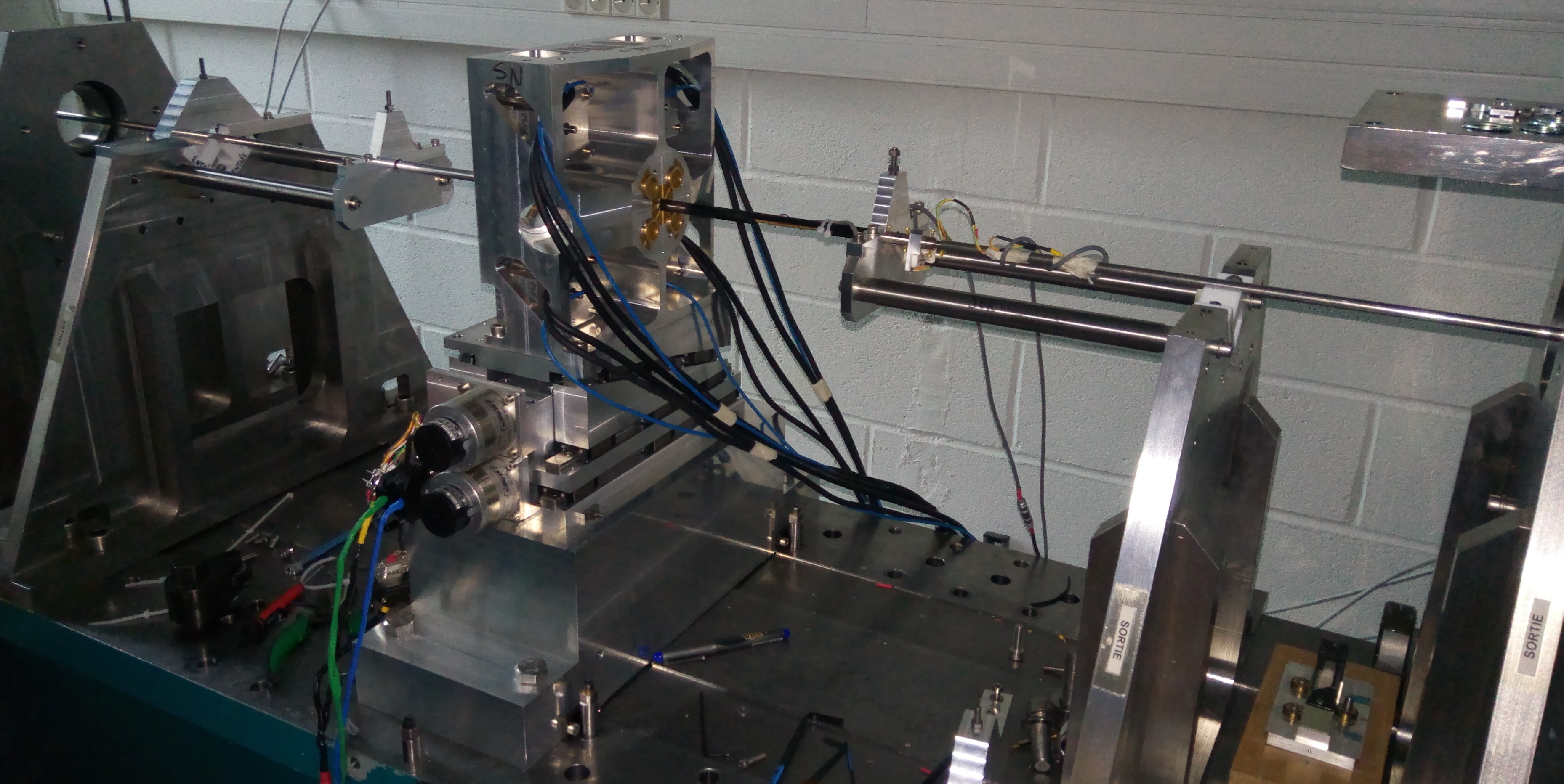
Different measurement methods have been used to characterize the magnetic field of the QUAPEVA. A rotating coil, built for the SOLEIL magnet characterization bench [16] shown in Fig. 4, to measure the field integral, and thus determine the gradient and magnetic center. A single stretched wire to measure the field integral which is similar to the rotating coil method concept. A pulsed wire method, where one applies a square current pulse through a wire and the use of a laser sensor to track the wire deflection that is proportional to the field[17].
While varying the gradient, some asymmetry will occur and cause magnetic center excursion. This excursion should be kept as small as possible due to the fact that the QUAPEVAs are used to focus a large energy spread beam, and if one tunes the gradient to focus a different energy the magnetic center should not change much. Fig. 5 shows the magnetic center excursion measurements for the first triplet, as the gradient is varied from minimum to maximum, using two methods stretched wire () and rotating coil (). The two measurements are in good agreement where the magnetic center excursion is kept within 10 m in both axes.
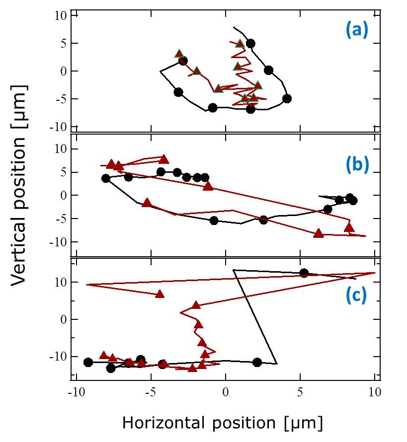
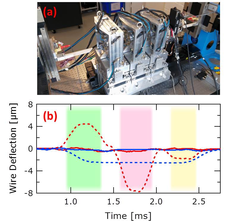
Before the commissioning of the first triplet, one must assure that the magnetic centers of the three QUAPEVAs are well aligned. Fig. 6-a shows the triplet installed at the pulsed wire measurement bench, to measure the magnetic centers of the QUAPEVAs. The QUAPEVAs were centered one by one, starting from the 40.7 mm, the 44.7 mm and finally the 26 mm. Fig. 6-b shows the wire deflection versus time before (dashed) and after (line) the adjustments of the translation tables. As the field is proportional to the displacement, the magnetic centers are well aligned when the deflection is 0. Thus good alignment has been achieved.
5 Application to COXINEL
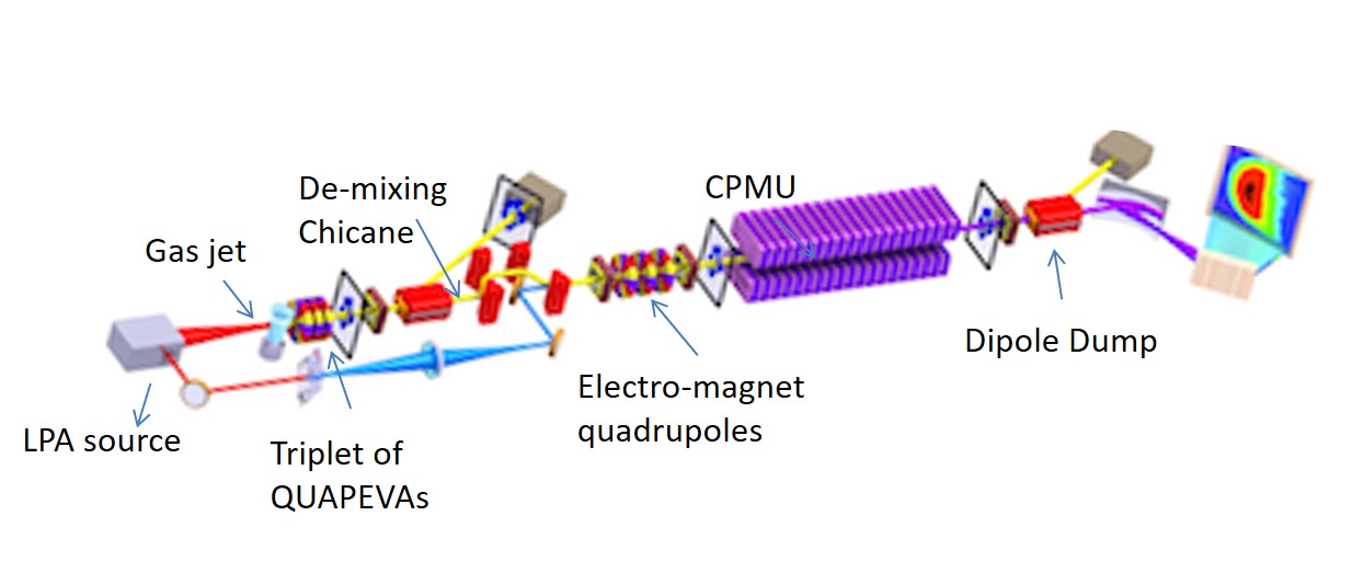
A set of triplet of QUAPEVAs had been installed at COXINEL and enabled to control the beam up to 10 m long of transport line passing through different magnetic elements. Since the electron beam quality does not directly fulfill the FEL requirements, a transport line has been designed to manipulate the electron beam characteristics, as shown in Fig. 7. The line starts with the triplet just after the gas jet where the electrons are produced, a de-mixing chicane composed of four electro-magnet dipoles to decompress the beam, followed by a set of four electro-magnet quadrupoles to ensure good focusing at the center of a undulator (2 m long with period length of 18 mm). Different diagnostics are installed along the transport line to measure the beam characteristics[13] at different locations.
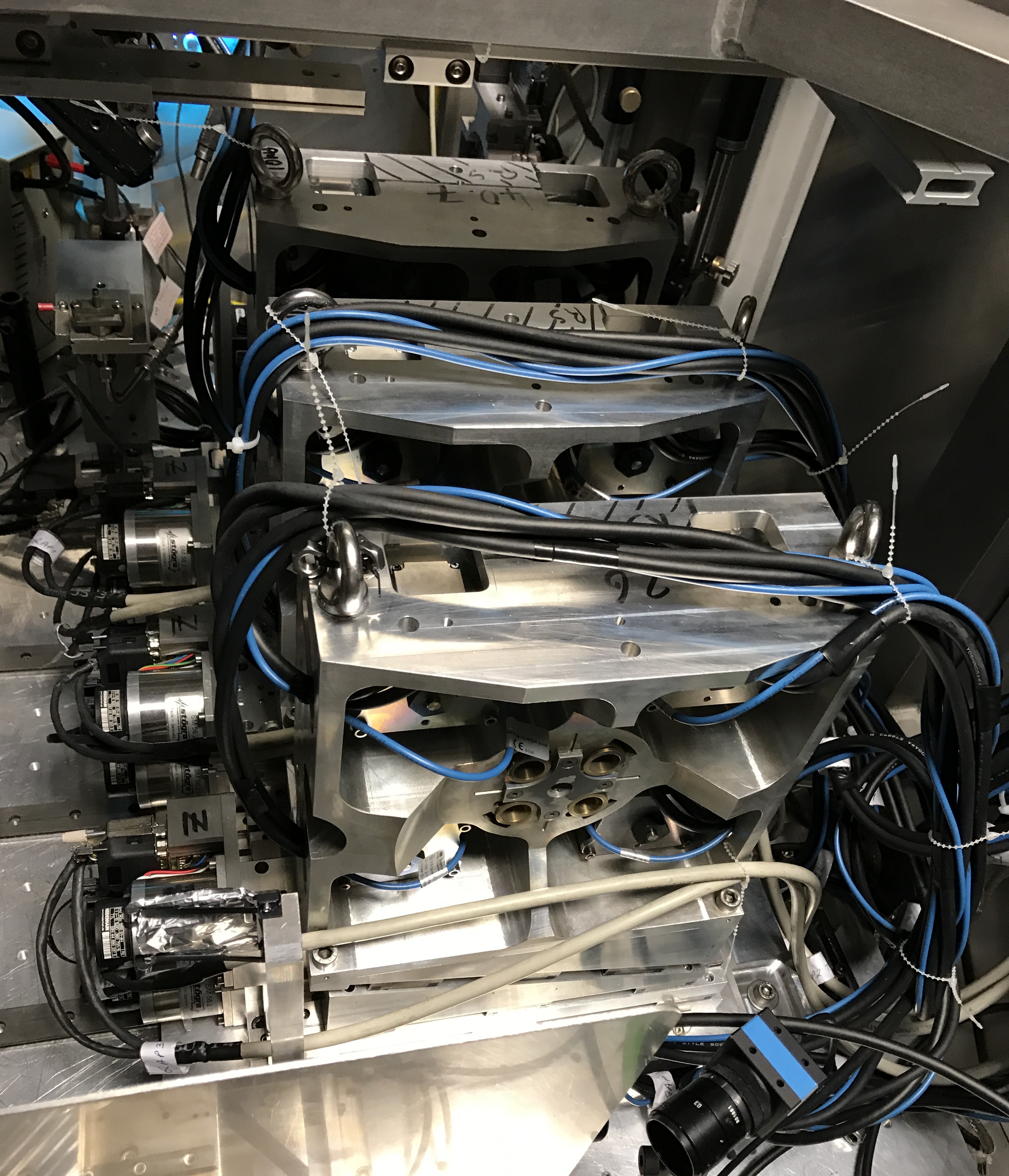
A view of the QUAPEVA installed in the gas jet chamber is shown in Fig. 8. Since the QUAPEVA are very close to the focused laser, magnetic measurements have been performed after magnets use. In spite of their use in severe environments (laser and electron beam collision with the magnets), it was observed that there was no variation on the gradient or field quality.
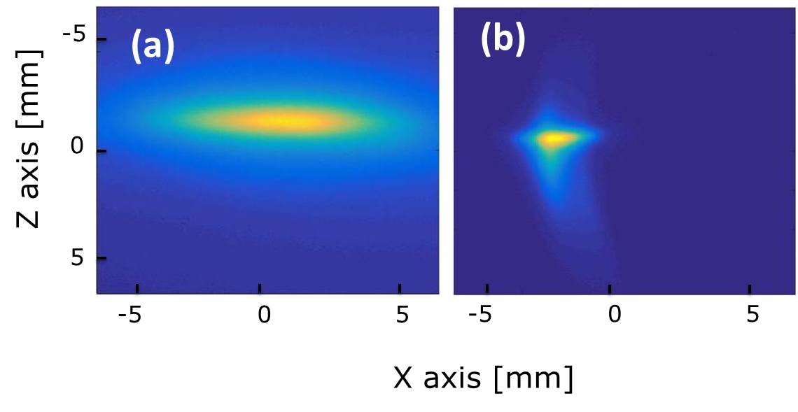
A beam observation on the first screen (LANEX) of COXINEL is shown in Fig. 9, (a) without and (b) with QUAPEVAs installed. The large divergence of the electron beam is properly controlled and focused enabling beam transport further on the beam line.
6 Conclusion
The design of a permanent magnet based quadrupole of variable gradient strength have been presented. A high gradient ( 201 T/m) with a wide tuning range ( 92 T/m) is obtained with such a design combining a Halbach ring surrounded by four cylindrical magnets. The measurement using different methods are consistent and in good agreement. The residual excursion of the magnetic center has been limited to a that can be compensated with the translation table. The quadrupoles have been installed successively at COXINEL beam line, and were able to achieve good focusing for a highly divergent large energy spread beam.
7 Acknowledgments
The authors are very grateful to the European Research Council for the advanced grant COXINEL (340015) and also to the Fondation de la Coopération Scientifique for the Triangle de la Physique / valorisation contract QUAPEVA (2012-058T). The authors are very thankful for the COXINEL team as well, and acknowledge the Laboratoire d’Optique Appliquée team led by V. Malka for the generation of the electron beam by laser plasma acceleration, enabling to use the QUAPEVAs.
References
- [1] V. Balakin, V. Alexandrov, A. Mikhailichenko, K. Flöttmann, F. Peters, G.-A. Voss, V. Bharadwaj, M. Halling, J. Holt, J. Buon, et al., Focusing of submicron beams for tev-scale e+ e- linear colliders, Physical Review Letters 74 (13) (1995) 2479.
-
[2]
K. Oide, M. Aiba, S. Aumon, M. Benedikt, A. Blondel, A. Bogomyagkov,
M. Boscolo, H. Burkhardt, Y. Cai, A. Doblhammer, B. Haerer, B. Holzer, J. M.
Jowett, I. Koop, M. Koratzinos, E. Levichev, L. Medina, K. Ohmi,
Y. Papaphilippou, P. Piminov, D. Shatilov, S. Sinyatkin, M. Sullivan,
J. Wenninger, U. Wienands, D. Zhou, F. Zimmermann,
Design of
beam optics for the future circular collider
collider rings, Phys. Rev. Accel. Beams 19 (2016) 111005.
doi:10.1103/PhysRevAccelBeams.19.111005.
URL https://link.aps.org/doi/10.1103/PhysRevAccelBeams.19.111005 - [3] K. Halbach, Permanent magnet undulators, Le Journal de Physique Colloques 44 (C1) (1983) C1–211.
- [4] W. Lou, D. Hartill, D. Rice, D. Rubin, J. Welch, Stability considerations of permanent magnet quadrupoles for CESR phase-III upgrade, Physical Review Special Topics-Accelerators and Beams 1 (2) (1998) 022401.
- [5] T. Mihara, Y. Iwashita, M. Kumada, A. Evgeny, C. M. Spencer, Super strong permanent magnet quadrupole for a linear collider, IEEE transactions on applied superconductivity 14 (2) (2004) 469–472.
- [6] J. Lim, P. Frigola, G. Travish, J. Rosenzweig, S. Anderson, W. Brown, J. Jacob, C. Robbins, A. Tremaine, Adjustable, short focal length permanent-magnet quadrupole based electron beam final focus system, Physical Review Special Topics-Accelerators and Beams 8 (7) (2005) 072401.
- [7] T. Eichner, F. Grüner, S. Becker, M. Fuchs, D. Habs, R. Weingartner, U. Schramm, H. Backe, P. Kunz, W. Lauth, Miniature magnetic devices for laser-based, table-top free-electron lasers, Physical Review Special Topics-Accelerators and Beams 10 (8) (2007) 082401.
- [8] P. NÕgotta, G. Le Bec, J. Chavanne, Hybrid high gradient permanent magnet quadrupole, Physical Review Accelerators and Beams 19 (12) (2016) 122401.
- [9] S. C. Gottschalk, K. Kangas, T. E. DeHart, J. T. Volk, C. M. Spencer, Performance of an adjustable strength permanent magnet quadrupole, in: Proceedings of the Particle Accelerator Conference, 2005. PAC 2005, IEEE, 2005, pp. 2071–2073.
- [10] T. Mihara, Y. Iwashita, M. Kumada, C. M. Spencer, Variable permanent magnet quadrupole, IEEE transactions on applied superconductivity 16 (2) (2006) 224–227.
- [11] B. J. Shepherd, J. A. Clarke, N. Marks, N. A. Collomb, J. A. Richmond, Novel Adjustable Permanent Magnet Quadrupoles for the CLIC Drive Beam Decelerator, IEEE Transactions on Applied Superconductivity 22 (3) (2012) 4004204–4004204.
- [12] M.-E. Couprie, A. Loulergue, M. Labat, R. Lehe, V. Malka, Towards a free electron laser based on laser plasma accelerators, Journal of Physics B: Atomic, Molecular and Optical Physics 47 (23) (2014) 234001.
- [13] M. Couprie, M. Labat, C. Evain, F. Marteau, F. Briquez, M. Khojoyan, C. Benabderrahmane, L. Chapuis, N. Hubert, C. Bourassin-Bouchet, et al., An application of laser–plasma acceleration: towards a free-electron laser amplification, Plasma Physics and Controlled Fusion 58 (3) (2016) 034020.
- [14] O. Chubar, P. Elleaume, J. Chavanne, A three-dimensional magnetostatics computer code for insertion devices, Journal of Synchrotron Radiation 5 (3) (1998) 481–484.
- [15] J. Simkin, C. Trowbridge, Three-dimensional nonlinear electromagnetic field computations, using scalar potentials, in: IEE Proceedings B-Electric Power Applications, Vol. 127, IET, 1980, pp. 368–374.
- [16] A. Madur, Contribution à la métrologie magnétique des multipôles d’accélérateurs: les quadrupôles du synchroton soleil, Ph.D. thesis, Vandoeuvre-les-Nancy, INPL (2006).
- [17] D. W. Preston, R. W. Warren, Wiggler field measurements and corrections using the pulsed wire technique, Nuclear Instruments and Methods in Physics Research Section A: Accelerators, Spectrometers, Detectors and Associated Equipment 318 (1-3) (1992) 794–797.