Universal Faraday rotation in HgTe wells with critical thickness
Abstract
The universal value of Faraday rotation angle close to the fine structure constant () is experimentally observed in thin HgTe quantum wells with thickness on the border between trivial insulating and the topologically non-trivial Dirac phases. The quantized value of the Faraday angle remains robust in the broad range of magnetic fields and gate voltages. Dynamic Hall conductivity of the hole-like carriers extracted from the analysis of the transmission data shows theoretically predicted universal value of consistent with the doubly degenerate Dirac state. On shifting the Fermi level by the gate voltage the effective sign of the charge carriers changes from positive (holes) to negative (electrons). The electron-like part of the dynamic response does not show quantum plateaus and is well described within the classical Drude model.
The strong spin-orbit coupling and an inverted band structure in mercury telluride makes this material to a nearly universal tool to probe novel physical effects with the film thickness being a tuning parameter Bernevig et al. (2006); Büttner et al. (2011). If the thickness of HgTe wells is below critical, nm, the sequence of the conduction and valence bands is conventional and a trivial insulating state is realized. For thicker films and in the bulk mercury telluride the inversion of valence and conduction bands leads to topologically non-trivial surface states Qi et al. (2008); Hasan and Kane (2010). This state is characterised by the locking of the electron spin and the electron momentum and they are topologically protected against non-magnetic impurity scattering.
If the thickness of HgTe well is equal to critical, the gap between valence and conduction bands disappears and a two-dimensional (2D) electron gas is formed with Dirac cone dispersion Bernevig et al. (2006); Büttner et al. (2011). Close to the center of the Dirac cone the electron spin is not a good quantum number, but has to be replaced by pseudo-spin or helicity Castro Neto et al. (2009); Qi et al. (2008). Due to the particle-hole symmetry of these states, the quantum Hall effect becomes shifted by a half-integer and takes the form . In well-investigated case of graphene Novoselov et al. (2005); Zhang et al. (2005) the states are fourfold degenerate, i.e. , as two Dirac cones are present in the Brillouin zone which are both doubly spin-degenerate.
Magneto-optics in the terahertz range has been proven to be an effective tool to investigate two-dimensional conducting states in several quantum systems, like graphene Crassee et al. (2011); Shimano et al. (2013); Orlita et al. (2012), Bi2Se3 Schafgans et al. (2012); Bordács et al. (2013); Wu et al. (2013); Olbrich et al. (2014), and HgTe Shuvaev et al. (2011); Hancock et al. (2011); Kvon et al. (2012); Zholudev et al. (2012); Shuvaev et al. (2013a); Olbrich et al. (2013); Zoth et al. (2014); Dantscher et al. (2015). Magneto-optical spectroscopy has the advantages of being contact-free and of directly accessing the effective mass via the cyclotron resonance . Here is the external magnetic field.
In the dynamical regime the unusual character of the quantum Hall effect in systems with Dirac cones can be shown Tse and MacDonald (2010a); Maciejko et al. (2010); Tse and MacDonald (2010b); Tkachov and Hankiewicz (2011) to lead to a universal values of the Faraday and Kerr rotation with and , respectively. Such predictions have been recently confirmed experimentally in graphene Shimano et al. (2013), where the Faraday angle is additionally doubled as two Dirac cones exist in the Brillouin zone. Very recently Okada et al. (2016); Wu et al. (2016); Dziom et al. (2016a), several groups announced the observation of the quantized Faraday and Kerr rotation from the surface states of various topological insulators. In our previous work Dziom et al. (2016a) the universal Faraday rotation has been observed on surface states in three-dimensional topological insulator, realised in thick strained HgTe film.
Compared to thick strained films with three-dimensional (3D) carriers, in HgTe wells with critical thickness a two-dimensional electron gas is realized. In this case there is no gap between the valence and conduction bands, resulting in Dirac dispersion of the 2D carriers. Due to double degeneracy of the Dirac cone the quantized dynamical Hall conductivity with may be expected.
In this manuscript we present the results of the terahertz experiments in HgTe quantum wells with critical thickness. Compared to graphene Shimano et al. (2013) here a single valley Dirac fermion system is realized revealing strong spin-orbit coupling. Critical sample thickness ensures 2D character of charge carriers which can be tuned using a transparent gate.
Mercury telluride quantum wells have been grown on (013) oriented GaAs substrates by molecular beam epitaxy as described elsewhere Kvon et al. (2009). The results on two samples with thickness close to critical are presented: sample #1 with nm and sample #2 with nm. The gate on both samples has been prepared ex-situ using a mylar film with m as an insulating barrier and a semi-transparent metallized film as a gate (Ti, ). In the experiment the gate conductivity is seen as magnetic field-independent and frequency independent contribution to . No measurable effect of gate on the Hall conductivity has been observed which agrees well with low mobility of the gate carriers.
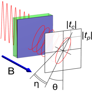
The experimental results in this work have been obtained using a Mach-Zehnder interferometer operating at sub-millimeter wavelengths (0.1-1 THz) Volkov et al. (1985). The interferometric arrangement has enabled to obtain the absolute values of complex transmissions through the sample in parallel and crossed polarisers geometries Shuvaev et al. (2012). The experimental procedure is shown schematically in Fig. 1. External magnetic fields up to 7 T have been applied using a superconducting magnet with polypropylene windows. The transmission experiments have been done in the Faraday geometry, i.e. magnetic field is applied along the propagation direction of the electromagnetic radiation. In total, four experimental parameters are measured and full characterization of the transmitted radiation is obtained including the polarization state. With this information, the Faraday rotation angle and ellipticity can be obtained directly Shuvaev et al. (2012); Shuvaev et al. (2013a); Dziom et al. (2016b).
Explicit equations to calculate the matrix of the conductivity from the measured transmission are given in Ref. Dziom et al. (2016b). In these calculations the effect of GaAs substrate and of Ti gate are taken into account exactly, i.e. pure HgTe conductivity is obtained. The measured Faraday rotation and ellipticity are still partly influenced by the properties of substrate and gate. Where appropriate, specific values of these angles will be given. The frequency of transmission experiment is chosen to minimize the influence of the substrate.
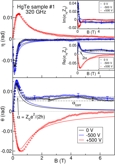
The most important result of this paper is demonstrated in Fig. 2. Here, the experimental Faraday rotation (lower panel) and ellipticity (upper panel) are shown for the sample #1. The peaks in the data at around T are the cyclotron resonances on free charge carriers in our sample. The sign change of the Faraday angle and ellipticity between negative and positive gate voltages corresponds to the transition from the hole-like to the electron-like carriers, respectively.
We note that in high magnetic fields far above the cyclotron resonance Shuvaev et al. (2013b), classical Faraday rotation and ellipticity are expected to fade out as . Remarkably, in Fig. 2 the experimental values of the Faraday rotation for zero and negative gate voltages saturates at fields above 1 T and stays constant within the experimental accuracy up to the highest field in our experiment (7 T). We note that similar broad steps in the quantum Hall resistivity have been recently observed in HgTe wells and attributed to heavy holes valleys reservoir effects Kozlov et al. (2015). The step in Faraday rotation reveals a universal value close to the fine structure constant , indicated in Fig. 2 by dashed lines. Dash-dotted line gives the value which takes into account the properties of the substrate and gate exactly Dziom et al. (2016b), and assuming , . The difference between both values of Faraday rotation and the experimental data are within the uncertainties of the present work. As discussed above, in HgTe with critical thickness a 2D electron gas with Dirac dispersion is realized with double degeneracy Bernevig et al. (2006); Büttner et al. (2011). Therefore, we attribute the observation of to doubly degenerate states each contributing by .
In order to demonstrate the discrepancy between the experimental data and classical cyclotron resonance, the fits within Drude model Tse and MacDonald (2011); Tkachov and Hankiewicz (2011) are shown as solid lines in Fig. 2. The Faraday rotation and the Faraday ellipticity of the electron-like carriers at positive gate voltage are well fitted within the classical response (red lines and symbols). The ellipticity at zero and negative gate voltages also follow the classical Drude model quite well. Remarkably, the experimental Faraday rotation in this region of the gate voltages behaves very distinctly from the predictions of the model. The model curves tend towards zero rather quickly at fields above 1 T (blue and black lines). Contrary, the experimental data shows abrupt deviation from the classical calculations at these fields, saturating at approximately constant level.
From the transmission spectra in zero magnetic field and at zero gate voltage the exact value of the refractive index of the substrate (optical thickness) is determined experimentally Shuvaev et al. (2012). With this parameter the transmission in both parallel and crossed geometries can be recalculated into the complex magneto-optical conductivity of mercury telluride Dziom et al. (2016b) without additional assumptions. The diagonal conductivity is mostly responsible for the parallel transmission in our experiments and for the dissipation in DC transport measurements. The off-diagonal conductivity is related to the transmission in the crossed geometry and for the quantum Hall plateaus in the DC experiments. is especially relevant for the emergence of the universal Faraday rotation and it is plotted in the inset of Fig. 2. The data are shown in a dimensionless form by multiplying the conductivity with the impedance of vacuum Ohm.
The upper inset in Fig. 2 shows the imaginary part of which appear at nonzero frequencies only. The real part of is shown in the lower inset. It also demonstrates the deviation from the classical Drude behaviour and saturates at the level slightly above the universal value of . We attribute this deviation to the uncertainties of the experiment.
From the Drude fits of the dynamic conducivity of sample #1 in the vicinity of cyclotron resonance the parameters of the charge carriers could be calculated which are given in Tab. 1. Much lower mobility of the electrons ( V) compared to holes ( V) is probably the reason that no quantized Faraday effect could be observed for positive voltages. High Dirac-hole mobility in HgTe wells can be explained by screening of their scattering by heavy holes Kozlov et al. (2013).
| Gate (V) | (cm-2) | (cmVs) | |
|---|---|---|---|
| -500 V | |||
| +500 V |
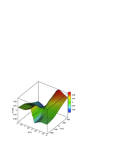
At a fixed frequency of the incident radiation GHz and at K there are two external parameters which can be tuned: magnetic field and gate voltage. A good overview of the experimental data set obtained by changing both parameters is provided by Fig. 3. Here, the color coded height represents the Faraday rotation as a function of magnetic field T T and of gate voltage V V in the direction of increasing voltage. The data shown in Fig. 2 are cuts of the parametric surface in Fig. 3 at fixed gate voltages. The cyclotron resonance peaks in Fig. 2 are also seen in Fig. 3. However, now it is possible to see the continuous evolution of the cyclotron resonances with the gate voltage. The positive peak at positive magnetic fields and gate voltage of V gradually disappears and transforms into a negative peak at V. This is a manifestation of the transition from the hole-like carriers at negative gate voltages to the electron-like carriers at the positive gates.
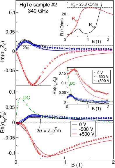
The main result of the present work, a plateau in Faraday rotation close to the universal value , is supported by the measurements on sample #2. Eight contacts have been prepared around the edges of sample #2, which allowed to measure DC longitudinal and transverse resistivities and . These data are shown in the upper inset of Fig. 4. The black curve is the longitudinal resistivity , the red curve represents the transverse resistivity . The pronounced plateau at fields between 0.75 and 1.5 T is clearly seen in the data. The value of the transverse resistivity at the plateau is around 25.8 k which can be expected if only the last quantum Hall plateau is observed and the degeneracy factor is equal to . The DC data correspond well to the universal value of the Faraday rotation . Indeed, in the limit of small absorption by thin film Shuvaev et al. (2013b) we may write: , which leads to for . Direct correspondence between quantum Hall effect and quantized Faraday rotation is well known in ordinary 2D electron gases Volkov and Mikhailov (1985).
The magneto-optical conductivity of sample #2 is shown in Fig. 4. The imaginary part in the upper panel reveals no plateau neither at the positive nor at the negative gate voltages. The real part of the conductivity shown in the lower panel demonstrates a clear plateau at fields above 1 T at zero and negative gate voltages. The value of this plateau equals to and it corresponds well to the DC data shown by green line. In the electron-like doping regime at the positive gate voltages no such plateau is observed in magnetic fields below 2 T.
An interesting difference between the DC and the THz conductivity of HgTe films is that the high frequency measurements show the robust plateau in the Faraday rotation up to 2 T in Fig. 4 and up to 7 T in Fig. 2, whereas the DC data the plateau is limited to the field range T. In addition, reveal clear indication of insulating behavior above 1.5 T. This could be due to the quantum Hall liquid-to-insulator transition Wang et al. (1994); Jiang et al. (1993); Shahar et al. (1995). In the static experiment the current has to follow the percolation path across the whole sample and the liquid-to-insulator transition sets in rather early. Contrary, at high frequencies the charge carriers are able to move a small distance only () during one period of the electromagnetic wave. Here Shuvaev et al. (2013a) is the Fermi velocity, s is the scattering time and is the frequency of the experiment. The less conducting regions of the sample are not participating in the overall response while the signal from the conducting parts is still present. Therefore one can expect that the transition to insulating state will disappear at high frequencies as observed here.
In conclusion, using polarisation- and phase-sensitive terahertz transmission spectroscopy, HgTe quantum wells with critical thickness have been investigated. In external magnetic fields a universal value of the Faraday rotation close to the fine structure constant is observed for hole-like carriers. Dynamic Hall conductivity is directly calculated from the experiment and it reveals a universal value which corresponds to a degeneracy of Dirac states. The universal steps in the dynamical conductivity and Faraday angle remain robust in a broad range of external magnetic fields and gate voltages. On the electronic side of the gate voltages a classical magneto-optical behavior is observed. It can attributed to much lower mobility of negatively charged carriers.
We thank G. Tkachov, E. M. Hankiewicz, and S.-C. Zhang for valuable discussions. This work was supported by Austrian Science Funds (I815-N16, W-1243, P27098-N27).
References
- Bernevig et al. (2006) B. A. Bernevig, T. L. Hughes, and S.-C. Zhang, Science 314, 1757 (2006), URL http://www.sciencemag.org/content/314/5806/1757.abstract.
- Büttner et al. (2011) B. Büttner, C. X. Liu, G. Tkachov, E. G. Novik, C. Brüne, H. Buhmann, E. M. Hankiewicz, P. Recher, B. Trauzettel, S. C. Zhang, et al., Nat. Phys. 7, 418 (2011).
- Qi et al. (2008) X.-L. Qi, T. L. Hughes, and S.-C. Zhang, Phys. Rev. B 78, 195424 (2008), URL http://link.aps.org/doi/10.1103/PhysRevB.78.195424.
- Hasan and Kane (2010) M. Z. Hasan and C. L. Kane, Rev. Mod. Phys. 82, 3045 (2010), URL http://link.aps.org/doi/10.1103/RevModPhys.82.3045.
- Castro Neto et al. (2009) A. H. Castro Neto, F. Guinea, N. M. R. Peres, K. S. Novoselov, and A. K. Geim, Rev. Mod. Phys. 81, 109 (2009), URL http://link.aps.org/doi/10.1103/RevModPhys.81.109.
- Novoselov et al. (2005) K. S. Novoselov, A. K. Geim, S. V. Morozov, D. Jiang, M. I. Katsnelson, I. V. Grigorieva, S. V. Dubonos, and A. A. Firsov, Nature 438, 197 (2005).
- Zhang et al. (2005) Y. Zhang, Y. Tan, H. Stormer, and P. Kim, Nature 438, 201 (2005).
- Crassee et al. (2011) I. Crassee, J. Levallois, A. L. Walter, M. Ostler, A. Bostwick, E. Rotenberg, T. Seyller, D. van der Marel, and A. B. Kuzmenko, Nat. Phys. 7, 48 (2011).
- Shimano et al. (2013) R. Shimano, G. Yumoto, J. Y. Yoo, R. Matsunaga, S. Tanabe, H. Hibino, T. Morimoto, and H. Aoki, Nat. Comm. 4 (2013).
- Orlita et al. (2012) M. Orlita, I. Crassee, C. Faugeras, A. B. Kuzmenko, F. Fromm, M. Ostler, T. Seyller, G. Martinez, M. Polini, and M. Potemski, New J. Phys. 14, 095008 (2012), URL http://stacks.iop.org/1367-2630/14/i=9/a=095008.
- Schafgans et al. (2012) A. A. Schafgans, K. W. Post, A. A. Taskin, Y. Ando, X.-L. Qi, B. C. Chapler, and D. N. Basov, Phys. Rev. B 85, 195440 (2012), URL http://link.aps.org/doi/10.1103/PhysRevB.85.195440.
- Bordács et al. (2013) S. Bordács, J. G. Checkelsky, H. Murakawa, H. Y. Hwang, and Y. Tokura, Phys. Rev. Lett. 111, 166403 (2013), URL http://link.aps.org/doi/10.1103/PhysRevLett.111.166403.
- Wu et al. (2013) L. Wu, M. Brahlek, R. V. Aguilar, A. V. Stier, C. M. Morris, Y. Lubashevsky, L. S. Bilbro, N. Bansal, S. Oh, and N. P. Armitage, Nat. Phys. 9, 410 (2013).
- Olbrich et al. (2014) P. Olbrich, L. E. Golub, T. Herrmann, S. N. Danilov, H. Plank, V. V. Bel’kov, G. Mussler, C. Weyrich, C. M. Schneider, J. Kampmeier, et al., Phys. Rev. Lett. 113, 096601 (2014), URL http://link.aps.org/doi/10.1103/PhysRevLett.113.096601.
- Shuvaev et al. (2011) A. M. Shuvaev, G. V. Astakhov, A. Pimenov, C. Brüne, H. Buhmann, and L. W. Molenkamp, Phys. Rev. Lett. 106, 107404 (2011), URL http://link.aps.org/doi/10.1103/PhysRevLett.106.107404.
- Hancock et al. (2011) J. N. Hancock, J. L. M. van Mechelen, A. B. Kuzmenko, D. van der Marel, C. Brüne, E. G. Novik, G. V. Astakhov, H. Buhmann, and L. W. Molenkamp, Phys. Rev. Lett. 107, 136803 (2011), URL http://link.aps.org/doi/10.1103/PhysRevLett.107.136803.
- Kvon et al. (2012) Z. D. Kvon, S. N. Danilov, D. A. Kozlov, C. Zoth, N. N. Mikhailov, S. A. Dvoretskii, and S. D. Ganichev, JETP Lett. 94, 816 (2012), URL http://dx.doi.org/10.1134/S002136401123007X.
- Zholudev et al. (2012) M. Zholudev, F. Teppe, M. Orlita, C. Consejo, J. Torres, N. Dyakonova, M. Czapkiewicz, J. Wróbel, G. Grabecki, N. Mikhailov, et al., Phys. Rev. B 86, 205420 (2012), URL http://link.aps.org/doi/10.1103/PhysRevB.86.205420.
- Shuvaev et al. (2013a) A. M. Shuvaev, G. V. Astakhov, G. Tkachov, C. Brüne, H. Buhmann, L. W. Molenkamp, and A. Pimenov, Phys. Rev. B 87, 121104 (2013a), URL http://link.aps.org/doi/10.1103/PhysRevB.87.121104.
- Olbrich et al. (2013) P. Olbrich, C. Zoth, P. Vierling, K.-M. Dantscher, G. V. Budkin, S. A. Tarasenko, V. V. Bel’kov, D. A. Kozlov, Z. D. Kvon, N. N. Mikhailov, et al., Phys. Rev. B 87, 235439 (2013), URL http://link.aps.org/doi/10.1103/PhysRevB.87.235439.
- Zoth et al. (2014) C. Zoth, P. Olbrich, P. Vierling, K.-M. Dantscher, V. V. Bel’kov, M. A. Semina, M. M. Glazov, L. E. Golub, D. A. Kozlov, Z. D. Kvon, et al., Phys. Rev. B 90, 205415 (2014), URL http://link.aps.org/doi/10.1103/PhysRevB.90.205415.
- Dantscher et al. (2015) K.-M. Dantscher, D. A. Kozlov, P. Olbrich, C. Zoth, P. Faltermeier, M. Lindner, G. V. Budkin, S. A. Tarasenko, V. V. Bel’kov, Z. D. Kvon, et al., Phys. Rev. B 92, 165314 (2015), URL http://link.aps.org/doi/10.1103/PhysRevB.92.165314.
- Tse and MacDonald (2010a) W.-K. Tse and A. H. MacDonald, Phys. Rev. B 82, 161104 (2010a), URL http://link.aps.org/doi/10.1103/PhysRevB.82.161104.
- Maciejko et al. (2010) J. Maciejko, X.-L. Qi, H. D. Drew, and S.-C. Zhang, Phys. Rev. Lett. 105, 166803 (2010), URL http://link.aps.org/doi/10.1103/PhysRevLett.105.166803.
- Tse and MacDonald (2010b) W.-K. Tse and A. H. MacDonald, Phys. Rev. Lett. 105, 057401 (2010b), URL http://link.aps.org/doi/10.1103/PhysRevLett.105.057401.
- Tkachov and Hankiewicz (2011) G. Tkachov and E. M. Hankiewicz, Phys. Rev. B 84, 035405 (2011), URL http://link.aps.org/doi/10.1103/PhysRevB.84.035405.
- Okada et al. (2016) K. N. Okada, Y. Takahashi, M. Mogi, R. Yoshimi, A. Tsukazaki, K. S. Takahashi, N. Ogawa, M. Kawasaki, and Y. Tokura, Nat. Comm. 7, 12245 (2016), URL http://www.nature.com/ncomms/2016/160720/ncomms12245/full/ncomms12245.html.
- Wu et al. (2016) L. Wu, M. Salehi, N. Koirala, J. Moon, S. Oh, and N. P. Armitage, ArXiv 1603.04317 (2016), URL http://arxiv.org/abs/1603.04317.
- Dziom et al. (2016a) V. Dziom, A. M. Shuvaev, G. V. Astakhov, G. Tkachov, C. Brüne, H. Buhmann, L. W. Molenkamp, A. Pimenov, and E. M. Hankiewicz, ArXiv 1603.05482 (2016a), URL http://arxiv.org/abs/1603.05482.
- Kvon et al. (2009) Z. D. Kvon, E. B. Olshanetsky, N. N. Mikhailov, and D. A. Kozlov, Low Temp. Phys. 35, 6 (2009), URL http://dx.doi.org/10.1063/1.3064862.
- Volkov et al. (1985) A. A. Volkov, Y. G. Goncharov, G. V. Kozlov, S. P. Lebedev, and A. M. Prokhorov, Infrared Phys. 25, 369 (1985), URL http://www.sciencedirect.com/science/article/B6X3W-46K4CH2-29/2/43ef2c1b497859011f2f67a144d4bb72.
- Shuvaev et al. (2012) A. M. Shuvaev, G. V. Astakhov, C. Brüne, H. Buhmann, L. W. Molenkamp, and A. Pimenov, Semicond. Sci. Technol. 27, 124004 (2012), URL http://stacks.iop.org/0268-1242/27/i=12/a=124004.
- Dziom et al. (2016b) V. Dziom, A. Shuvaev, N. N. Mikhailov, and A. Pimenov, ArXiv 1603.05926 (2016b), URL http://arxiv.org/abs/1603.05926.
- Tse and MacDonald (2011) W.-K. Tse and A. H. MacDonald, Phys. Rev. B 84, 205327 (2011), URL http://link.aps.org/doi/10.1103/PhysRevB.84.205327.
- Shuvaev et al. (2013b) A. Shuvaev, A. Pimenov, G. V. Astakhov, M. Muhlbauer, C. Brune, H. Buhmann, and L. W. Molenkamp, Appl. Phys. Lett. 102, 241902 (2013b), URL http://link.aip.org/link/?APL/102/241902/1.
- Kozlov et al. (2015) D. A. Kozlov, Z. D. Kvon, N. N. Mikhailov, and S. A. Dvoretskii, JETP Letters 100, 724 (2015), URL http://dx.doi.org/10.1134/S0021364014230076.
- Kozlov et al. (2013) D. A. Kozlov, Z. D. Kvon, N. N. Mikhailov, and S. A. Dvoretsky, JETP Letters 96, 730 (2013), URL http://dx.doi.org/10.1134/S0021364012230099.
- Volkov and Mikhailov (1985) V. A. Volkov and S. Mikhailov, JETP Lett. 41, 476 (1985).
- Wang et al. (1994) T. Wang, K. P. Clark, G. F. Spencer, A. M. Mack, and W. P. Kirk, Phys. Rev. Lett. 72, 709 (1994), URL http://link.aps.org/doi/10.1103/PhysRevLett.72.709.
- Jiang et al. (1993) H. W. Jiang, C. E. Johnson, K. L. Wang, and S. T. Hannahs, Phys. Rev. Lett. 71, 1439 (1993), URL http://link.aps.org/doi/10.1103/PhysRevLett.71.1439.
- Shahar et al. (1995) D. Shahar, D. C. Tsui, M. Shayegan, R. N. Bhatt, and J. E. Cunningham, Phys. Rev. Lett. 74, 4511 (1995), URL http://link.aps.org/doi/10.1103/PhysRevLett.74.4511.