Design, Control and Visual Navigation of the DelftaCopter
Abstract
To participate in the Outback Medical Express UAV Challenge 2016, a vehicle was designed and tested that can hover precisely, take-off and land vertically, fly fast forward efficiently and use computer vision to locate a person and a suitable landing location. A rotor blade was designed that can deliver sufficient thrust in hover, while still being efficient in fast forward flight. Energy measurements and windtunnel tests were performed. A rotor-head and corresponding control algorithms were developed to allow transitioning flight with the non-conventional rotor dynamics. Dedicated electronics were designed that meet vehicle needs and regulations to allow safe flight beyond visual line of sight. Vision based search and guidance algorithms were developed and tested. Flight tests and a competition participation illustrate the applicability of the DelftaCopter concept.
Nomenclature
| CASA | = | Civil Aviation Safety Authority |
| IMU | = | Inertial Measurement Unit |
| GPS | = | Global Positioning System |
| UAV | = | Unmanned Air Vehicle |
| VTOL | = | Vetical Take-Off and Landing |
1 Introduction
It has always been a goal in aviation to design aircraft which are efficient and controllable from hover to very fast forward flight. Unfortunately requirements for fast and slow flight are very contradictory [1]. While hybrid aircraft have existed for a long time, the search for the ultimate combination is still ongoing [2, 3, 4, 5, 6, 7, 8]. With the advent of unmanned air vehicles, several hybrid aircraft concepts that were previously impracticable have gained new interest [9, 8].
The applications of aircraft with combined efficient long-range flight and hovering capabilities are numerous. Typical examples are operation from ships or within forests.
1.1 Medical Express Challenge
A sample use-case for Vertical Take-Off and Landing (VTOL) aircraft with long-range capabilities is the Outback Medical Express UAV Challenge 2016. The Outback UAV Challenge has a long history of creating realistic but very hard challenges for teams to improve the state of the art [10, 11, 12].
The 2016 edition of the Outback UAV Challenge was called Medical Express and has set its competition goals to stimulate the development of aircraft with both hovering and long-range flight capabilities. The competition requires an unmanned vehicle to take-off from a model airstrip in Dalby Australia and fly to a remote location km away which had often been inaccessible due to floods. At the location, a lost bush-walker must be located. The unmanned vehicle must then select a suitable landing location within meters from the found person, but for safety reasons may never come closer than meters to the person [13]. After an automatic vertical landing, medical assistance is delivered before flying back to base with a medical sample.
1.2 Long-Distance VTOL
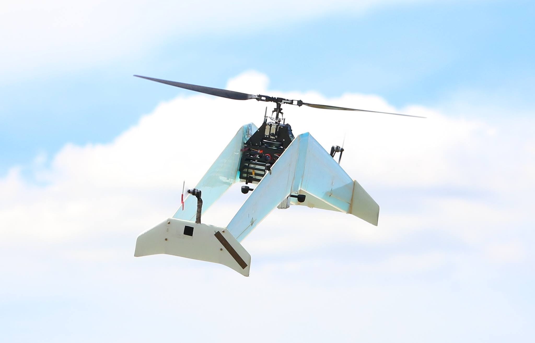
This paper proposes a novel UAV design (See Figure 1) that combines efficient and high control authority hover with efficient long-range fast flight. While the design was optimized for the Outback Medical Express, it has applications far beyond. It features a large rotor for hovering with cyclic and collective pitch control combined with a biplane delta-shaped wing for efficient forward flight and all avionics and computer vision needed to turn it into a flying robot. During hover, all lift is provided by the main rotor and it uses tip-rotors and ailerons to compensate for the main rotor torque. During forward flight it pitches down almost degrees and transitions to a fixed-wing aircraft with a large propeller as illustrated in Figure 2. Many drawbacks of this so-called tail-sitter when used for manned flight [14] don’t apply to UAV, while its advantages remain.
Compared to coaxial counter rotating rotor designs, the chosen concept of a single rotor is much simpler and does not require axle in axle. In hover DelftaCopter is basically a helicopter and in forward flight the motor rpm is reduced and the rotor blade pitch is increased to reach flight speeds of around to m/s to cover the required km in under an hour even in case of winds up to kt.
The flying wing of DelftaCopter has the advantage of being simple and compact. It also yields advantages in the VTOL phases. Natural wind has a severe wind gradient close to the ground [15]. When hovering, the top of the aircraft experiences a higher wind velocity than the lower part which calls for aircraft without a long tail.
The choice for a biplane was made on three grounds:
-
•
A single wing has more surface area exposed to the wind in VTOL mode than two wings behind each other. This diminishes the perturbations of take-off and landing in wind.
-
•
The two wings and fins at the tips yield a nice big footprint for stable ground handling.
-
•
A biplane configuration allows a higher range of angles of attack [16] which is important in the transition from hover to forward flight and back.
1.3 Outline
The outline of the paper is as follows. First a propulsion system for both hover and forward flight is derived in Section 2. Then the energy consumption (Section 3) is addressed. Based on available propulsion and energy, the aerodynamic and structural design are detailed in Section 4. Wind tunnel measurements are analyzed in Section 5. The electrical design is explained in Section 6. Control of the DelftaCopter is explained in Section 7 and Section 8. The on-board computer vision follows in Section 9. The flight is described in Section 10 and finally the Conclusions and Recommendations follow in Sections 11 and 12.
2 Propulsion Design
The design of a propulsion system that is efficient in the wide range from fast forward flight down to stationary hovering flight is always a challenge. For DelftaCopter, the propulsion is designed to be a compromise between efficient hover and efficient forward flight. This results in a rotor blade that is significantly different from rotors seen in conventional helicopters.
The maximum efficiency for hover is obtained using a single large rotor [17]. Also for forward flight this is the most efficient [1]. While in theory a single blade rotor is more efficient than a two blade rotor, in practice several implications still make the dual blade more practicable than a single blade.
The rotor blades are designed with significant twist, yielding a substantial performance increase over a flat rotor. The use of twist is possible thanks to the transitioning as—unlike in conventional helicopters—the rotor can always be kept in an axial flow regime.
2.1 Propeller Design
For an efficient hover the diameter has to be big enough to reach a reasonable figure of merit [17]. For forward flight where the power is significantly less than for hover the big diameter can be accepted when the rpm is reduced and the pitch is increased.
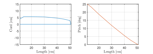
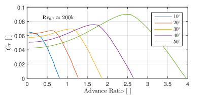
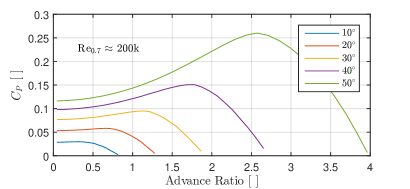
The design process was supported with the use of PropCalc 3.0 [18]555See http://www.drivecalc.de/PropCalc/. A diameter of meter was selected as a between hover and forward flight requirements. A mild twist of degrees from root to tip was applied. For the airfoil the MA409 section was chosen being targeted at Reynolds numbers of and below. The design point for hover was rpm with tip pitch angle. For forward flight it was around rpm with tip pitch angle.
During the wind tunnel measurements and flight tests the drag of all external appendages was found to be higher than estimated in the concept phase, which gave us the need to lower the pitch and increase the rpm. This also increased the responsiveness needed to climb more quickly when required. The new cruise condition was around tip pitch angle with rpm. In cases where responsiveness or excess thrust are required, pitch with rpm was utilized.
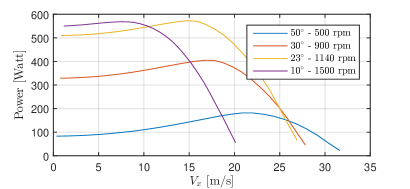
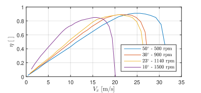
The resulting propeller is shown in Figure 3 and the size is given in Table 1. Characteristics are given in Figures 7,8,9,4,5 and 6.
| x [cm] | [cm] | |
|---|---|---|
| 11 | 4 | 25.0 |
| 14 | 5.7 | 23.2 |
| 20 | 5.7 | 18.7 |
| 30 | 5.5 | 11.8 |
| 40 | 4.6 | 5.5 |
| 45 | 3.9 | 2.6 |
| 50 | 2.8 | 0.2 |
| 50.7 | 1.0 | 0 |
2.2 Motor
Once the propeller design was shown to yield good efficiency in both flight regimes, a corresponding motor was chosen capable of delivering the required torque and power. A direct-drive sensor-less brush-less direct current (BLDC) motor was selected.
2.3 Silent
DelftaCopter produces noise equivalent to a medium sized quadrotor when hovering, with most noise originating from the tip props. But when in forward flight, DelftaCopter becomes very silent. During the transition from hover to forward flight, most of the noise disappears when the x inch tip propellers are turned off. This reduced noise production is considered to be a significant benefit of using one large efficient rotor with high pitch, low RPM and a direct drive motor.


3 Energy
An energy profile was derived from the mission requirements. It consists of a higher load phase during vertical take-off, followed by an endurance phase at lower load and another high load phase during the landing. For the competition, after a short down time, there is also a return flight with the same profile (See Figure 10).
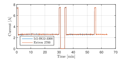
Several types of electrical energy are available. Common battery technologies for electric UAV are Lithium-Polymer and Lithium-Ion batteries. Even higher energy densities can be achieved using fuel cells [19]. But because of the short mission time of less than 1 hour and high flight speed involved in the competition, the depletion rate is also important.
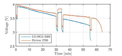
No fuel cells could be found within the weight budget and power rating. To make the choice between the more energy dense Lithium-Ion and higher current rated Lithium-Polymer types a test setup was built. The LG-HG2-3300 Lithium-Ion battery was trade off against the Extron 2700 Lithium Polymer battery in a test setup which submitted the cells to the competition load. Figure 11 shows the test results in which large differences can be observed. While the Lithium-Ion cells contain more energy under slow discharge, under high load they delivered less power and in the end could not deliver the needed power needed for the final landing. Finally the Lithium-Polymer cells were selected for DelftaCopter.
4 Airframe Design
Given the propulsion system, energy package and rotor-head mechanics, a fixedwing airframe was designed. The airframe needs to generate lift during fast forward flight with little drag, but at the same time it must also accommodate all the systems of the flying robot. Finally it must provide structural stability for the airframe to land as a rotorcraft.
4.1 Structural
When DelftaCopter is in hover, the wing acts as a landing gear but also makes the helicopter more sensitive to lateral gusts. To address both problems at once, a biplane wing was selected. This has the advantage that the total lateral surface area in hover is significantly reduced. This means its size and corresponding moments are reduced, while the two wings provide a stable rectangular basis for landing.
4.2 Aerodynamic Design
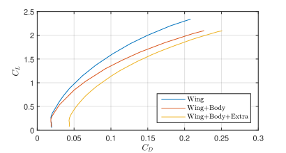
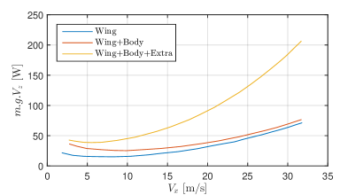
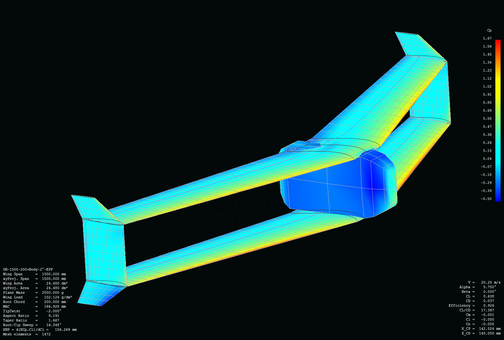
A delta-shaped auto-stable flying wing concept was selected. This removes the need for a vertical stabilizer and fits well behind the main rotor. Lift and Drag computations were performed using XFLR [20]. Figure 12 shows a view from the 3D model.
Figure 13 shows the insertion of the fuselage has almost no influence on at due to the inviscid calculation. At higher angles of attack the influence is significant. The drag due to the non-streamlined fuselage, the rotorhead, motor cooling and all protrusions like head antennae etc is added as an extra term. This is taken as a based on the total wing area to lead to a more realistic drag.
5 Wind Tunnel Analysis
In a typical scenario, DelftaCopter would spend most of its time in forward flight. Therefore, optimizing the energy efficiency in forward flight is key to improving the range of the vehicle. While computations in Section 2 predicted an efficiency increase in forward flight with lower rpm, this could not easily be seen during flight tests. A possible explanation could be that the motor is less efficient at low RPM, canceling the performance gain from the propeller. To verify this, windtunnel measurements were performed.
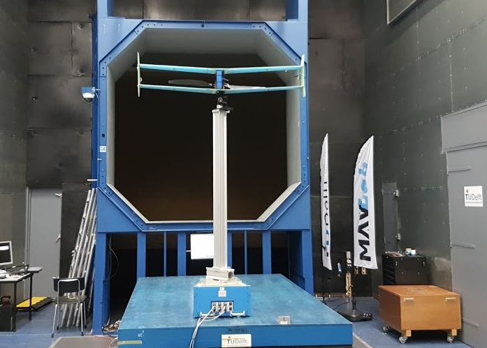
In order to assess the propulsive efficiency and to find the optimal propulsion settings, a wind tunnel experiment was performed. The Open Jet Facility at Delft University of Technology was used for this experiment. The vehicle was placed in the middle of the m by m wind tunnel outlet, with zero angle of attack. The DelftaCopter was rigidly attached to a pole, which was mounted on a force-moment balance below the wind tunnel outlet as shown in Figure 15.
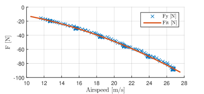
First the drag of the pole and attachment without the DelftaCopter was measured. Figure 16 shows the resulting fit which finds a drag of . Then DelftaCopter is mounted on the pole in the middle of the open jet wind tunnel. Measurements are taken at several representative airspeeds, namely at , , and m/s. For each airspeed, DelftaCopter parameters are measured through a range of main rotor collective pitch angles and power settings. The settings are selected manually such that no rpm, current or motor temperature limitation is breached. The rotor is turning at all times as soon as the wind tunnel is blowing, and windmills even when no power is applied.
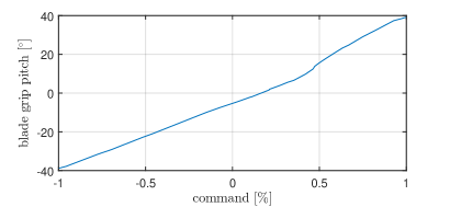
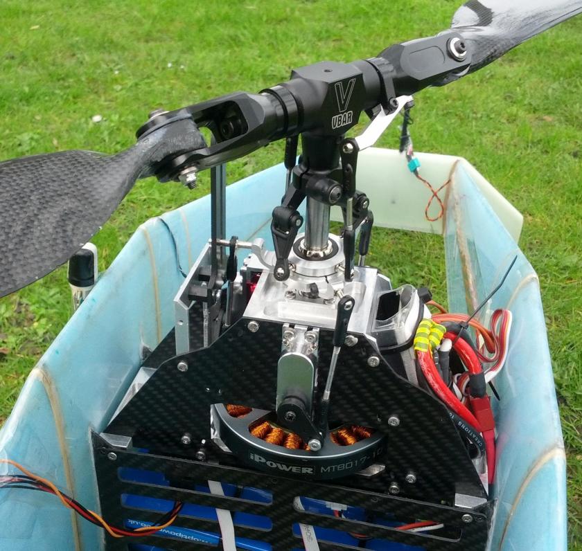
One extra lab measurement is made to convert the servo pitch commands into an actual collective pitch angle. The non-linearity of the rotor-head linkages is non-trivial as seen in Figure 17. A close-up photo of the rotor-head can be found in Section 8 Figure 22.
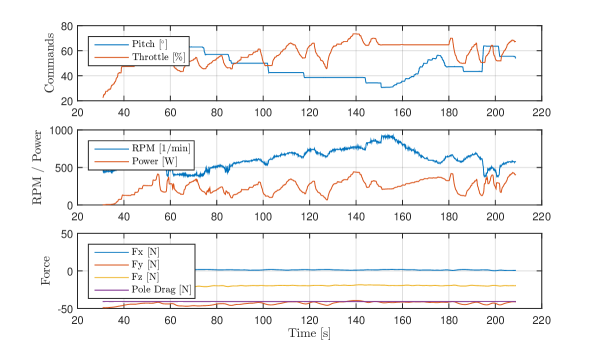
During the windtunnel runs, all on-board data like IMU and airspeed are logged. Of special interest are the motor current and rpm together with the throttle setting and collective pitch setting. In parallel the windtunnel system logged all forces and moments on the balance and the windtunnel calibrated airspeed (See Figure 18). From the data it was expected to find a clear sweet spot, namely a throttle versus pitch setting where better efficiency could be obtained.
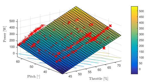
However, it was found that power and rpm wise, pitch and throttle can be exchanged without significant difference in power efficiency. Figure 19 shows a planar fit predicting the stationary used power based on the pitch and throttle input. Identical results are obtained at other windtunnel velocities. The plane fits the data very well with most off-plane points corresponding to temporary changes in power setting. When in Figure 19 contour lines of the fit are followed from left to right, one finds settings for pitch and throttle that consume the same amount of power but result in a different rpm.
Several other interesting observations can be made from the windtunnel data. The force graph in Figure 18 for instance shows that DelftaCopter does not have a very large spare thrust in fast forward flight. This looks significantly less than the values found in Figure 4 because of electrical inefficiencies and because the windtunnel test did not include points overloading the motor. Finally it can be seen that the highest thrust is obtained at higher rpm values.
Overall it can be concluded that DelftaCopter can exchange rpm and pitch without very significant change in efficiency but that higher thrust can be achieved with higher rpm and higher maximum velocity can only be achieved with higher pitch settings.
6 Electronic Design
To comply with the strict requirements of the Outback Medical Challenge [13] and be allowed to fly beyond visual line of sight (BVLOS) missions at up to km distance, a custom electronic design was required. It consists of two independently powered circuits.
As seen in Figure 20, the first part is called flight termination device. This part has all the safety critical functions like driving actuators but also geo-fencing and long-range kill switches, motor un-powering and arming.
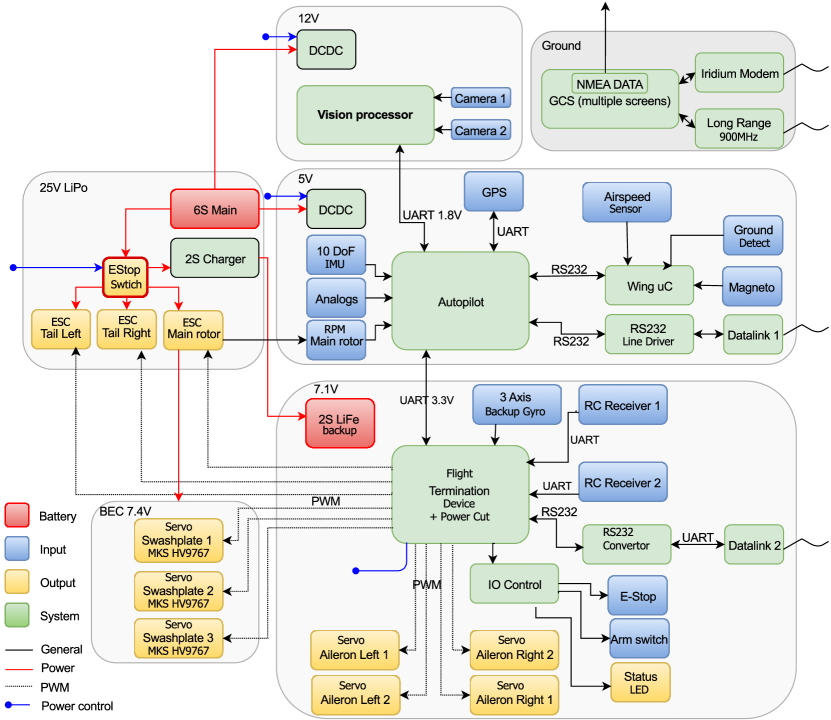
All navigation and control functions together with the flight plan logic are in the other part called autopilot. Both parts are modification of the Paparazzi-UAV [21] Lisa-MX autopilot [22].
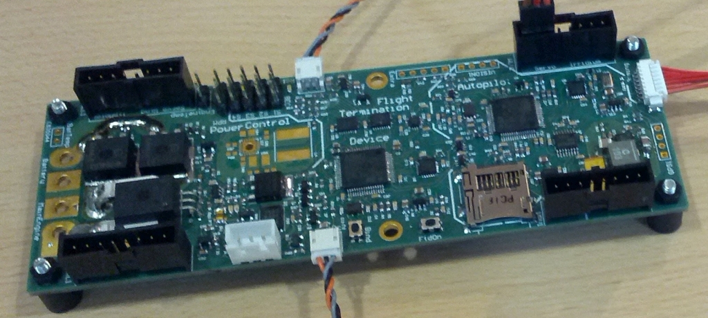
Because of the number of extra functions and boards, like SD-card logging, master power cut-off, line drivers to modems in wings, power converters, current voltage and temperature sensors, the design started to grow larger. To minimize interconnection failures and minimize the total weight, a custom PCB was designed with all needed functions which is shown in Figure 21.
7 Rotorhead Dynamics
Rotorcraft dynamics have been well studied for many years [17, 23, 24, 25, 26, 27, 28, 29]. But the properties of the light efficient rotor on a large heavy fuselage found in DelftaCopter are significantly different from what is seen in conventional helicopter control.
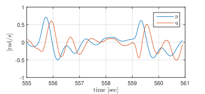
Early test flight attempts showed very significant unexplained behavior even in windless indoor hovering flight. Figure 23 shows how pitch commands were highly coupled with roll commands and vice verse. To investigate this behavior a theoretic model was derived.
7.1 Rotor
To investigate the dynamics of the DelftaCopter rotor and fuselage, a simplified model was derived [30]. Figure 24 illustrates the basic rotor model with rotor radius and spinning rate . The flapping angle is measured around the spring hinge and the feathering angle is periodic and follows the setting of the swash-plate cyclic and collective control. The resulting equation of motion of a rotor-blade can be written as:
| (1) |
in which is the so-called Lock Number [17]. The terms in Equation 1 from left to right relate first the inertia of the rotor, its aerodynamic damping, the centrifugal and spring forces to the external excitation. This concise notation clearly shows that besides rotor rpm , the rotor dynamics depend mostly on a single entity Lock Number :
| (2) |
As given in Equation 2, the Lock Number physically contains aerodynamic damping terms (air density , chord , rotor radius and lift coefficient ) divided by flapping inertia . In the DelftaCopter design the Lock Number is relatively high as the lift coefficient and radius are large while the mass and resulting inertia are very small.
7.2 Fuselage
To simulate and understand observed pitch and roll couplings a fuselage model is added. Fuselage inertia is playing a crucial role in the control when the fuselage inertia becomes significant compared to the rotor inertia [30]. In DelftaCopter the weight is spread over the very long wing with a lot of electronics like radios and antennas being placed in the wing tips for electronics reasons. The total weight of DelftaCopter is over kg while a rotor blade is only about g and the rotor rpm is kept as low as practicable for power reasons. The fuselage inertia can be modeled as shown in Figure 25.
The rotor and body interact with each other in the following ways. Even in case of a fully hinged rotor with , when the fuselage rotates, the rotor will automatically follow through the functioning of the swash-plate. In case of non zero an additional moment will be applied from the fuselage on the rotor whenever they are not in-line. The other way around a moment is transferred from rotor to fuselage through spring and another moment exists whenever the total lift is not going through the fuselage center of gravity. Forces through the swash-plate linkages are neglected.
7.3 Simulation
The combined effect of a light high-lift rotor and heavy non-symmetric fuselage can be clearly visualized in simulation. A model with parameters found in [30] is given a step input in pitch using a standard helicopter swash-plate as modeled in Equation 3.
| (3) |
The resulting cross couplings between pitch and roll for different body inertia are shown in Figure 26. A pitch cyclic doublet is applied. The simulation results clearly show the resulting desired pitch rate but show a highly different undesired coupling in roll rate which it totally different based on the inertia of the fuselage.
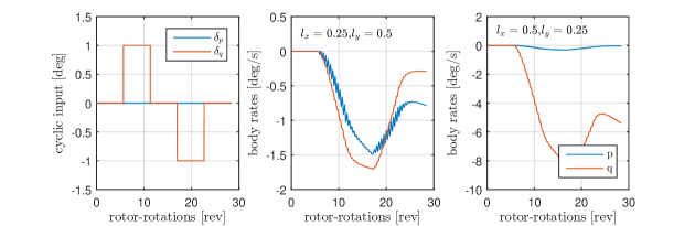
In other words, when the rotational inertia of the fuselage is large in pitch and less in roll, then a pitch command on the rotor will start pitching up the rotor plane. The fuselage inertia counteracts this rotation and will result in a pitch down moment on the rotor. The precession of the rotor will turn this into a rolling motion.
A controller for DelftaCopter will therefore need to compensate for cross couplings in pitch and roll body motions.
8 Control
The innerloop control of DelftaCopter is an angular rate controller. The outputs of the rate controller are cyclic commands and , which are mapped to the three servos , and that control the swash-plate shown in Figure 22 using Equations 4–6.
| (4) | |||||
| (5) | |||||
| (6) |
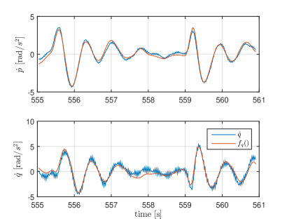
Using the on-board SD logging, data was collected in flight to identify the coupled vehicle dynamics. From Section 7 the angular acceleration in pitch and roll are expected to result from the cyclic inputs and , the rates in roll and pitch . An offset is added to the fit to compensate for trim errors. The control model is shown in Equations 7 and 8, where and are linear functions of the parameters.
| (7) |
| (8) |
Figure 27 shows the angular acceleration in roll and pitch along with the best fit of and for a short indoor flight fragment where DelftaCopter keeps a constant rpm of rpm during a degree step in roll. All signals were filtered with a second order filter with a cutoff frequency of rad/s. From the figure it can be seen that this model fit can explain most of the behavior for this part of the flight. The coefficients that were found using the data shown in Figure 27 are given in Table 2.
| Coefficient | ||
|---|---|---|
| -2.4661 | -2.8847 | |
| 0.0032 | -0.0044 | |
| 0.0011 | 0.0073 | |
| -0.5703 | 7.4479 | |
| -3.4308 | -3.4487 |
When looking closely at the coefficients for and in Table 2, they confirm that a roll rate causes a pitch acceleration and vice verse.
Taking into account the identified couplings, the linear controller is revised to:
| (9) |
Where and are the difference between the pilot command and the actual rates of the vehicle, and
| (10) |
An in-flight tuning parameter is introduced with a value between 0 and 1. It was introduced in order to gradually enable the compensation of angular acceleration due to rates. Test flights showed that a value of gives better results than a value of . This may be caused by actuator dynamics, as a control moment can not be instantly generated when a rate is measured. More research is necessary to better explain why still gives a wobble.
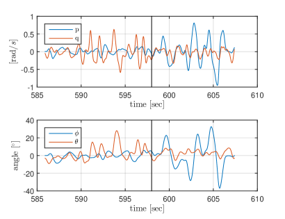
Figure 28 shows the measured angular rates of the vehicle during some pitch maneuvers in the first part of the flight and some roll maneuvers in the second part of the flight. The rates were filtered with a second order filter with a cutoff frequency of rad/s. From Figure 28 it can be seen that no wobble is present, and the motion in roll and pitch is uncoupled. When compared back to the initial situation in Figure 23, one can see that the control was highly improved.
9 Vision
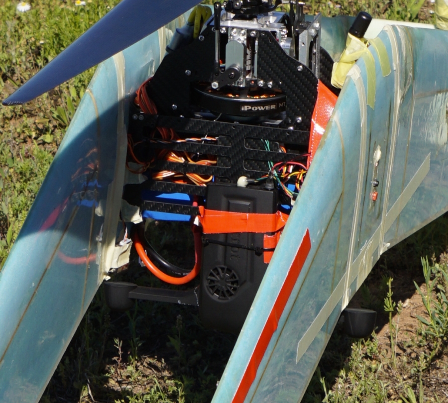
DelftaCopter was equipped with a state of the art computer vision system as can be seen in Figure 29: a prototype of the Parrot S.L.A.M.dunk.
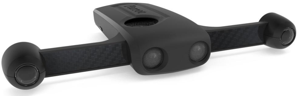
Our prototype666The unit used in DelftaCopter was a prototype product in development, the S.L.A.M.dunk will have improved specifications at release time. S.L.A.M.dunk API delivered a 96x96 pixels depth map which, if overlaid over the original camera image, was the center 640x480 pixel range, cropped from the full 1280x1024 camera resolution. The depth map was generated at fps, by means of Semi Global Matching accelerated by the GPU. On DelftaCopter the S.L.A.M.dunk looked straight down towards the ground when in hover mode, as can be seen in Figure 33.
| Processor | Nvidia Tegra TK1 |
|---|---|
| Cameras | 1280x1024 RGB |
| Depth map | 640x480 |
| Frame rate | 30 fps |
| Stereo base line | cm |
| Lenses | Fish eye |
| Sensors | 10-DOF IMU and sonar |
This system was used for: 1) detection of Joe, 2) landing spot selection, 3) obstacle avoidance during landing and 4) determining the moment of touchdown. Lastly, a feature was devised to automatically calibrate the attitude error between the airframe and the S.L.A.M.dunk. The hardware specifications are shown in Table 3.
9.1 Find Joe
The competition organizers only provide an approximate GPS position of bushwalker Joe ( meters accuracy) [31] while strict requirements were imposed on landing locations. Therefore the vision system needed to search and pinpoint the exact position of Joe. The Medical Outback challenge rules dictate to keep a minimum distance of meters from Joe in all directions, in order to comply with CASA (airspace regulatory body in Australia) regulations. In practice this meant DelftaCopter needed to maintain a minimum height of meters while searching in order to account for height measurement errors and gusts. Joe was to be visible in a field near a farm, wearing a normal blue jean and an Australian Akubra head.
Due to limitations imposed by the fish-eye lens, the overall quality of the images of Joe taken from a moving and vibrating platform at meters was low due to blur and low spatial resolution. Joe was reported to be standing upright, which is why a birds-eye view could be advantageous to detect pose and human parts features [32]. This non perpendicular view resulted in an increased observation distance to Joe, and even smaller pixel representations. Moreover, no example data of the Australian scene or Joe was available beforehand to us, complicating methods that need many training examples [33], and due to ongoing development on DelftaCopter itself, vision test flights on the final platform were scarce. Therefore, emphasis was placed on an algorithm simple enough to test and tune at the last moment on the Australian scene. Instead of using a real human for Joe, a full-size dressed dummy was used. This means no movement or thermal features could be used [34]. Instead, a simple color plus shape filter was used as a salience detector to detect possible Joes, which were clustered based on there projected GPS locations. The best exemplary thumbnails of each cluster were selected, cut out, and updated as a better view angle become available. These thumbnails, accompanied with their projected GPS positions and Joe likelihood scores (how many consecutive frames Joe could be detected at a given location) were calculated, and sent over the data link to the ground control station. A video of the Joe detection algorithm in action can be viewed online 777Joe detection: https://www.youtube.com/watch?v=GVTHuwg3VJY.
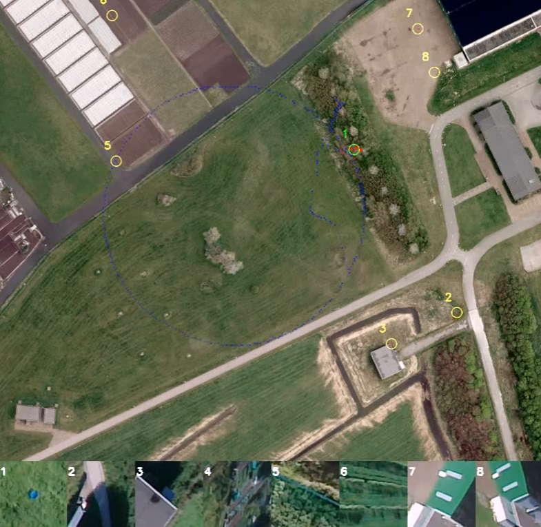
The vision operator was shown an interface with a map, numbers and list with accompanying thumbnails as shown in Figure 30. The blue dots show the flight path, the red dots show Joe sightings, the yellow circles shows the average location of the clustered red dots and the green circle shows the winning Joe sighting based on the highest Joe likeliness score. During the competition flight, a flight pattern in the shape of a W was pre-programmed to cover the whole possible area.
9.2 Selecting a landing spot
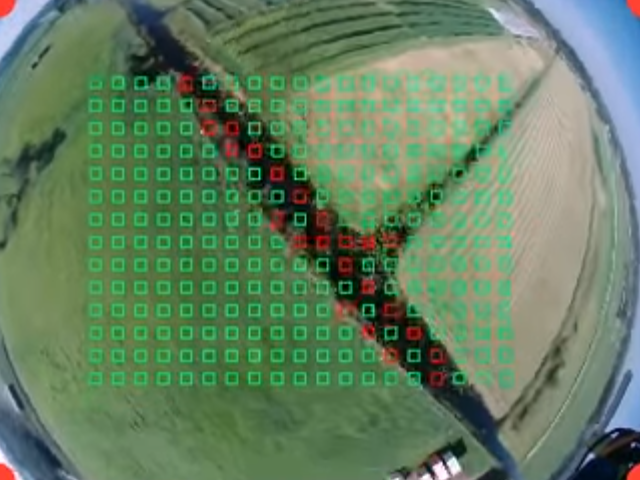
During the search for Joe, the surface was analyzed at the same time for landibility. Textures of areas with a known good surface (farmers land, grass, desert, road, etc) and bad surface (water, trees, roofs, etc) were annotated beforehand, and during flight classified with a simple Euclidean distance texture comparison on sub-sampled patches from the video stream as shown in Figure 31. A video of the on-board results can be viewed online888Landing spot classification: https://www.youtube.com/watch?v=RQ6F2ccMv8g. On this result, a blob-finder was applied and the biggest blob close to the selected Joe was automatically converted to the landing waypoint.
9.3 Obstacle avoidance
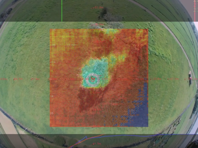
The landing site is in a natural, unstructured and unfamiliar environment which means the likelihood of unforeseen obstacles such as houses or trees is high. Some assumptions on the environment are made. It is assumed that in the targeted area the surface is commonly flat enough for the DelftaCopter to land. Furthermore, although obstacles are assumed to be of frequent occurrence, they are assumed to be sparsely located such that enough room exists between (small groups of) obstacles to land. During hover, the S.L.A.M.dunk is looking downwards and an algorithm based on the depth map provided by the S.L.A.M.dunk is implemented to land safely. The depth-map can detect obstacles up to m away but has significant noise in the farthest m. To prevent false positives from the depth map the landing is only enabled at heights lower then m above ground level (AGL). The IMU is information is used to determine the pixel location in the image that is straight down. This is especially important in the DelftaCopter design that can fly at considerable bank angles in hover in windy conditions. During landing a circular area in the image around the current straight down pixel is selected. A moving average depth is calculated in this area in order to determine the closest distance, the average distance and the minimum distance. Flatness is defined as the closeness between the minimum and maximum to the average. When the flatness is sufficiently high according to a threshold, the surface is considered safe for further fast descend. Otherwise, the aircraft is re-positioned towards the area with the greatest depth. A proportional gain is steering DelftaCopter laterally away from the global minimum of the moving average depth around the aircraft while the descend speed is decreased. Several tests showed DelftaCopter to be able to avoid all obstacles visible in stereo vision depth map during landing, like for instance trees and structures. A video of the on-board results can be viewed online 999Landing obstacle avoidance: https://www.youtube.com/watch?v=2eCi8VJiDcs.
9.4 Touch down
To make repeatable precise and smooth landings, predicting the exact moment of touchdown is very important. The S.L.A.M.dunk can measure the height to the ground from over m down to cm by mixing the sonar and the stereo depth. This precise height combined with DelftaCopter attitude information from the autopilot provides the required information to time landings successfully repeatedly. A video of a full autonomous landing can be viewed online101010Full autonomous flight: https://www.youtube.com/watch?v=8aakE1WlQQ0.
9.5 Attitude error calibration
The S.L.A.M.dunk was designed to be removable in order to allow easy access to the battery and electronics inside DelftaCopter. This can cause a possible discrepancy in the attitude between the camera and the airframe, depending on the mounting process. However, an exact attitude measurement is necessary in order to precisely geo-locate obstacles and Joe. Using the difference between the IMU embedded in the S.L.A.M.dunk and the IMU of the autopilot, the offset in attitude is determined automatically during the start-up phase. This lowers the requirements on the mounting system significantly.
10 Flight
10.1 Transitioning flight
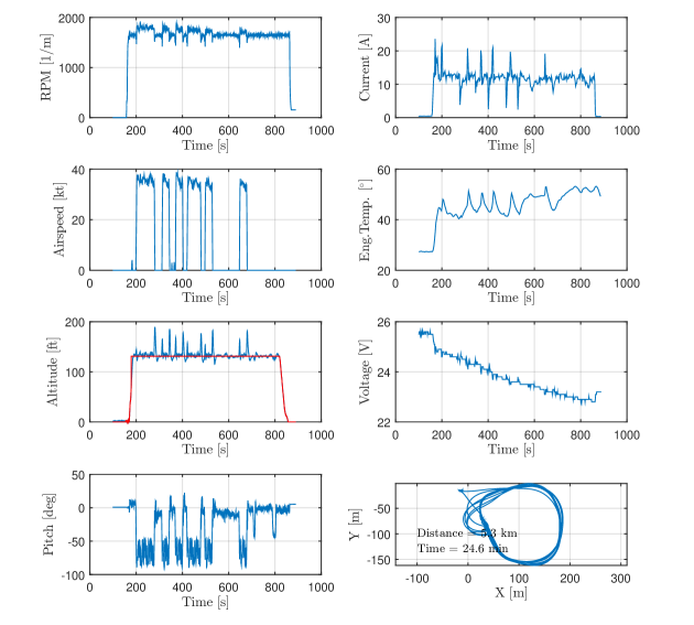
Figure 34 shows a flight with 6 transitions from hover to forward flight and back. During a transition from hover to forward, DelftaCopter has a small drop in altitude of about ft. During the transition back from fast forward flight back to hover a much more significant altitude overshoot is observed of about ft due to excess energy during the fast transition. The flight is performed in a very confined area of about by and in forward flight DelftaCopter is turning most of the time. Figure 34 also shows how during every hover the engine temperature is rising due to the increased load.
10.2 Efficiency Testing
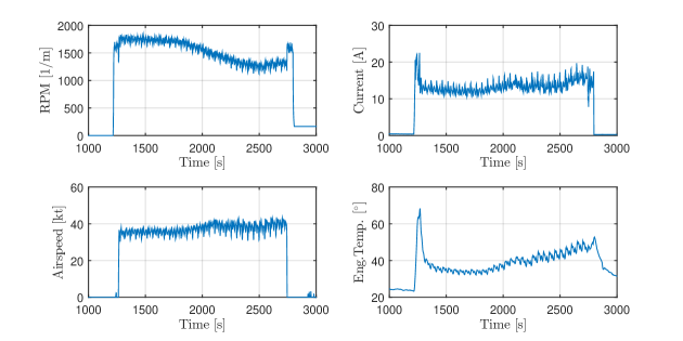
During another test flight shown in Figure 35 an attempt is made to find the most optimal forward flight regime. The design from Section 2 was suggesting that lower rotor RPM in forward flight should be more efficient. The actual flight data does however not clearly show an efficiency increase. This corresponds exactly to the windtunnel observations from Section 5. The rising motor temperature shows that the high motor load does decrease the electrical efficiency. Since no loss of total efficiency is observed, this means the propeller efficiency indeed increases but is undone by the loss of electric motor efficiency.
10.3 Competition Flight
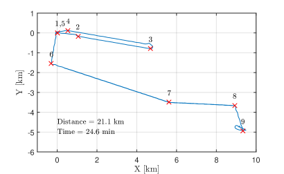
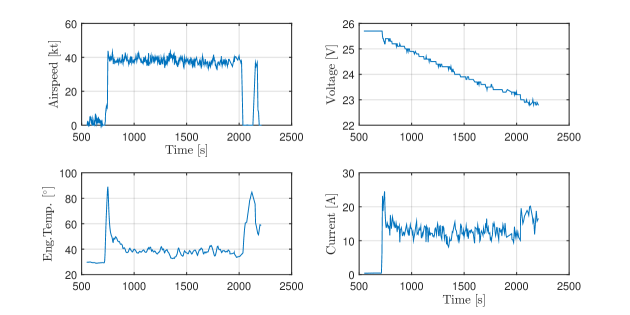
A top view of the competition flight from take-off at point 1 to the destination at point 9 is shown in Figure 36. The total traveled distance to Joe is Nm or km one-way. Figure 37 depicts the corresponding flight parameters of the competition flight. DelftaCopter was carrying a Ah 6-cell Lithium-Polymer battery pack of kg.
11 Conclusion
11.1 Concept
The DelftaCopter concept was selected for its efficient hovering with one large rotor, control authority in hover with fast cyclic control, simple and structurally strong biplane delta-wing design that also serves as landing gear and yields improved stall behavior over single wings. The biplane also reduces the lateral surface affected by turbulence and wind during hover of this tail-sitter VTOL aircraft. DelftaCopter was built, tested in a windtunnel setup and in-flight and participated in the Outback Medical Express Challenge 2016 where it won the seconds prize111111http://www.delftacopter.nl/.
The concept is applicable to a variety if scenarios, especially when long-distance and efficient hovering at minimal weight are driving requirements.
11.2 Propulsion
The hover efficiency of DelftaCopter is high thanks to it large single low rpm optimized rotor. The energy efficiency during fast forward flight turned out to be lower than expected from computations. This is most likely due to higher than expected airframe drag of the final built combined with significantly reduced motor efficiency at high torque.
11.3 Control
The cyclic control of DelftaCopter yields very fast and powerful attitude control. But without taking into account the rotor-fuselage dynamics, unacceptable couplings were observed. When designing hybrid aircraft mixing conventional cyclic controlled helicopters and fixed wings, it is crucial to understand the interactions between rotor and wing in order to optimize the design. The Lock Number and rotor hinge spring stiffness where shown to influence the speed of the rotor response. When adding a high inertial fuselage to the model, it showed the same type of behavior in simulation as the real DelftaCopter. The non-homogeneous inertia of the fuselage and fuselage-rotor interactions adds non-symmetrical couplings between the pitch and roll axes and affect the direction of the control effectiveness of the swash-plate. Compensation for the above effects was derived an converted to a controller strategy to remove unwanted couplings sufficiently for flight.
11.4 Vision
The stereo depth map properties of the S.L.A.M.dunk 121212S.L.A.M.dunk from https://www.parrot.com/ allow nice planning around obstacles and selection of flat areas during landing. But because of the very wide field-of-view fish-eye lenses, the resolution of the images when flying at cruise altitude is low. This makes reliable fully autonomous search for persons at a higher altitude very difficult. A salient detector with human feedback option was developed to automate the mission as much as possible while allowing human validation of the selected target.
12 Recommendations
The current design has shown outstanding efficiency in hovering flight and slightly less efficiency than predicted during forward flight. During the Outback Medical Express Challenge but also most other application scenarios of DelftaCopter, the forward flight phase is the predominant mode of flight.
A future design could therefore place slightly less emphasis on hover efficiency and more on forward flight where some efficiency gains highly affect the operational range and flight speed. A smaller diameter rotor/propeller will also put less demand on the torque requirements of the direct drive motor which was currently overloaded in fast forward flight.
When higher torque direct drive brushless motors become available, they could also yield efficiency improvements in fast forward flight.
Acknowledgments
We thank the sponsors of the TU-Delft Outback Medical Challenge Entry to have made this research possible.
Appendix
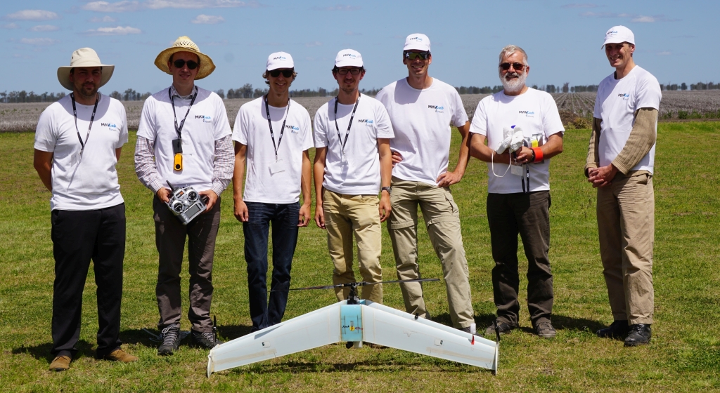
Figure 38 shows the three views of DelftaCopter with sizing information. Key specification values of DelftaCopter are repeated in Table 4. Finally Figure 39 gives an overview of the team.
| Property | Value |
|---|---|
| Weight | kg |
| MTOW | kg |
| Weight | kg |
| Wing Area | |
| Wing Loading | |
| Span | m |
| Length | m |
| Height | m |
| Cruise speed | kt at Watt |
| Most efficient speed | kt at Watt |
| Maximum speed | kt |
| Main battery | Ah 6 Cell LiPo |
| FTD battery | mAh 2 Cell LiFe |
References
- [1] John David Anderson. Aircraft Performance & Design, volume 1. WCB/McGraw-Hill Boston, 1999.
- [2] KC Wong, Jose Alfredo Guerrero, David Lara, and Rogelio Lozano. Attitude stabilization in hover flight of a mini tail-sitter uav with variable pitch propeller. In 2007 IEEE/RSJ International Conference on Intelligent Robots and Systems, pages 2642–2647. IEEE, 2007.
- [3] Yijie Ke, Kangli Wang, and Ben M. Chen. A preliminary modeling and control framework for a hybrid uav j-lion. In Prof. Zhihong PENG and Dr. Feng LIN, editors, International Micro Air Vechicle Competition and Conference 2016, pages 28–34, Beijing, PR of China, okt 2016.
- [4] Maxime Itasse, Jean-Marc Moschetta, Ryan Carr, and Yann Ameho. Equilibrium transition study for a hybrid mav. In Guido de Croon and Matthijs Amelink, editors, Proceedings of the International Micro Air Vehicle Conference and Flight Competition 2011 Summer Edition, pages 79–86, ’t Harde, the Netherlands, September 2011.
- [5] Marten Schütt, Philipp Hartmann, and Dieter Moormann. Fullscale windtunnel investigation of actuator effectiveness during stationary flight within the entire flight envelope of a tiltwing mav. In G. de Croon, E.J. van Kampen, C. De Wagter, and C. de Visser, editors, International Micro Air Vechicle Competition and Conference 2014, pages 77–83, Delft, The Netherlands, aug 2014.
- [6] Duc-Kien Phung and Pascal Morin. Modeling and energy evaluation of small convertible uavs*. IFAC Proceedings Volumes, 46(30):212 – 219, 2013.
- [7] Ertuğrul Çetinsoy, Serhat Dikyar, Cevdet Hançer, KT Oner, E Sirimoglu, M Unel, and MF Aksit. Design and construction of a novel quad tilt-wing uav. Mechatronics, 22(6):723–745, 2012.
- [8] Juan Escareno, RH Stone, A Sanchez, and Rogelio Lozano. Modeling and control strategy for the transition of a convertible tail-sitter uav. In Control Conference (ECC), 2007 European, pages 3385–3390. IEEE, 2007.
- [9] C De Wagter, D Dokter, G de Croon, and B Remes. Multi-lifting-device uav autonomous flight at any transition percentage. In Proceeding of: EuroGNC, volume 2013, 2013.
- [10] David Erdos and Steve E Watkins. Uav autopilot integration and testing. In Region 5 Conference, 2008 IEEE, pages 1–6. IEEE, 2008.
- [11] David Boura, Danny Hajicek, and William Semke. Automated air drop system for search and rescue applications utilizing unmanned aircraft systems. Infotech@ Aerospace, St. Louis, Missouri, pages 29–31, 2011.
- [12] David Erdos, Abraham Erdos, and Steve E Watkins. An experimental uav system for search and rescue challenge. IEEE Aerospace and Electronic Systems Magazine, 28(5):32–37, 2013.
- [13] Reece A Clothier, Brendan P Williams, and Neale L Fulton. Structuring the safety case for unmanned aircraft system operations in non-segregated airspace. Safety science, 79:213–228, 2015.
- [14] Takaaki Matsumoto, Koichi Kita, Ren Suzuki, Atsushi Oosedo, Kenta Go, Yuta Hoshino, Atsushi Konno, and Masaru Uchiyama. A hovering control strategy for a tail-sitter vtol uav that increases stability against large disturbance. In Robotics and Automation (ICRA), 2010 IEEE International Conference on, pages 54–59. IEEE, 2010.
- [15] CW Thornthwaite and Paul Kaser. Wind-gradient observations. Eos, Transactions American Geophysical Union, 24(1):166–182, 1943.
- [16] Elmer Carl Olson and BP Selberg. Experimental determination of improved aerodynamic characteristics utilizing biplane wing configurations. Journal of Aircraft, 13(4):256–261, 1976.
- [17] Anthony RS Bramwell, David Balmford, and George Done. Bramwell’s helicopter dynamics. Butterworth-Heinemann, 2001.
- [18] Helmut Schenk. PropCalc - propeller calculator software. http://www.drivecalc.de/PropCalc/, 2007.
- [19] James Larminie, Andrew Dicks, and Maurice S McDonald. Fuel cell systems explained, volume 2. J. Wiley Chichester, UK, 2003.
- [20] M Drela, H Youngren, M Scherrer, and A Deperrois. Xflr-5, 2012.
- [21] Pascal Brisset, Antoine Drouin, Michel Gorraz, Pierre-Selim Huard, and Jeremy Tyler. The paparazzi solution. In MAV 2006, 2nd US-European Competition and Workshop on Micro Air Vehicles, pages pp–xxxx, 2006.
- [22] Balazs Gati. Open source autopilot for academic research-the paparazzi system. In American Control Conference (ACC), 2013, pages 1478–1481. IEEE, 2013.
- [23] Raymond W Prouty. Helicopter performance, stability, and control. Krieger Publishing Company, Melbourne, FL 32902-9542 USA, 1995.
- [24] Walter J. Wagtendonk. Principles of Helicopter Flight. Aviation Supplies & Academics Inc, 1996.
- [25] Wayne Johnson. A comprehensive analytical model of rotorcraft aerodynamics and dynamics. part 1. analysis development. Technical report, NASA Ames Research Center, DTIC Document, 1980.
- [26] Wieslaw Zenon Stepniewski and CN Keys. Rotary-wing aerodynamics. Courier Corporation, 1979.
- [27] Vladislav Gavrilets. Dynamic model for a miniature aerobatic helicopter. In Handbook of Unmanned Aerial Vehicles, pages 279–306. Springer, 2015.
- [28] H Shim, Tak John Koo, Frank Hoffmann, and Shankar Sastry. A comprehensive study of control design for an autonomous helicopter. In Proc. 37th IEEE Conf. on Decision and Control, pages 1–6. Citeseer, 1998.
- [29] Gareth D Padfield. Helicopter flight dynamics. John Wiley & Sons, 2008.
- [30] Christophe De Wagter and Ewoud Smeur. Control of a hybrid helicopter with wings. Journal of Micro Air Vehicles, 2016.
- [31] Outback organization. Uav challenge medical express competition rules 2016 v4. 2016.
- [32] Piotr Rudol and Patrick Doherty. Human body detection and geolocalization for uav search and rescue missions using color and thermal imagery. In Aerospace Conference, 2008 IEEE, pages 1–8. IEEE, 2008.
- [33] Diulhio Candido De Oliveira and Marco Aurelio Wehrmeister. Towards real-time people recognition on aerial imagery using convolutional neural networks. In Real-Time Distributed Computing (ISORC), 2016 IEEE 19th International Symposium on, pages 27–34. IEEE, 2016.
- [34] Anna Gaszczak, Toby P Breckon, and Jiwan Han. Real-time people and vehicle detection from uav imagery. In IS&T/SPIE Electronic Imaging, pages 78780B–78780B. International Society for Optics and Photonics, 2011.