Further author information: (Send correspondence to S.M.)
S.M.: E-mail: sminardi@aip.de, Telephone: +49 (0) 331 7499 687
Beam combination schemes and technologies for the Planet Formation Imager 111Copyright 2016 Society of Photo-Optical Instrumentation Engineers. One print or electronic copy may be made for personal use only. Systematic reproduction and distribution, duplication of any material in this paper for a fee or for commercial purposes, or modification of the content of the paper are prohibited. DOI: http://dx.doi.org/10.1117/12.2232656
Abstract
The Planet Formation Imager initiative aims at developing the next generation large scale facility for imaging astronomical optical interferometry operating in the mid-infrared. Here we report on the progress of the Planet Formation Imager Technical Working Group on the beam-combination instruments. We will discuss various available options for the science and fringe-tracker beam combination instruments, ranging from direct imaging, to non-redundant fiber arrays, to integrated optics solutions. Besides considering basic characteristics of the schemes, we will investigate the maturity of the available technological platforms at near- and mid-infrared wavelengths.
keywords:
Stellar interferometry, future interferometric facilities, multi-telescope beam combiners.1 INTRODUCTION
The Planet Formation Imager (PFI) initiative[1, 2, 3] is aiming at developing the next generation large scale facility for imaging astronomical optical interferometry at mid-infrared wavelength. The main scientific goal of the PFI facility will be the high-angular-resolution characterization of planet forming regions and young Jupiter-mass exoplanets in the neighborhood of our Sun[4, 5]. This science case justifies the choice of the operating optical bands (from L to Q), due to the favorable contrast between the central star and the low-mass companions achievable at mid-infrared wavelengths. Due to the long operating wavelengths, maximal baselines in the order of 1 Km will be necessary to resolve the Hill sphere (i.e. the radius of the gravitational sphere of influence of a forming planet) of a Jupiter mass planet, estimated to be approximatly mas at the distance of the nearest star forming region (140 pc).
A conceptual technical study is currently underway to identify suitable key technologies for the realization of the PFI facility (see Ireland et al. 2016[6] for an overview of the current status of the technical study). Here we report on the progress of the Technical Working Group (TWG) on the beam-combination instruments. The goal of this TWG is to identify eventually the architecture and underlying technology for the beam combination instruments needed for PFI. Our working baseline scenario considers an array of 12 to 21, adaptive-optics-equipped telescopes and two alternative options for the science beam combination, namely a dispersed heterodyne[7](bands N and Q) or a dispersed homodyne scheme (L,M,N bands). In both cases, fringe tracking at near-infrared wavelengths will be necessary to access faint targets, thus requiring an additional beam-combiner instrument, most probably operating in the near-infrared.
This paper will review the state-of-the-art of homodyne multi-telescope beam combiners encompassing bulk, fiber and integrated optical solutions (Section 2). In Section 3 we will use a simple numerical model to compare the intrinsic per-baseline sensitivity of three different beam combination architectures assuming a coherence retrieval algorithm based on the Visibility to Pixel Matrix formalism (V2PM[8]). In Section 4 we will discuss the state-of-the-art of photonics technologies for the mid-infrared which could enable the manufacturing of the science beam-combiner for PFI. A discussion of the present technological challenges and a tentative roadmap for the development of a mid-infrared beam combination instrument measuring most of the available baselines at PFI are proposed in Section 5. Conclusions and recommendations are presented in Section 6.
2 REVIEW OF HOMODYNE BEAM COMBINATION INSTRUMENTS
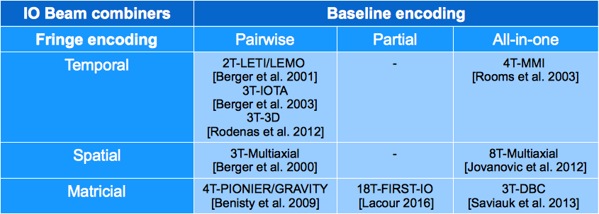
In this Section, we will present existing interferometric beam combination solutions broadly classified by key technologies and/or combination concepts. In particular, we will consider beam combiners based on bulk optics, optical fibers and integrated optics technologies, as well as discussing the concept of direct imaging. Throughout the text, we will also adopt the conventional high-level classification of multi-telescope beam combiners according to the fringe and baseline encoding (see Le Bouquin et al. 2004[9]). Fringe encoding can be temporal, spatial or matricial depending on whether the interference fringes are measured in temporal/spatial domain or recorded from the outputs of a phase-shifting interferometry set-up. Notice that spatial and matricial schemes can also be operated in temporal fringe scanning mode at the expense of a lower sensitivity. The baseline encoding can be pairwise, partial or all-in-one. Pairwise combiners encode at each output fringes resulting from a single pair of telescopes. In partial encoding the baselines are divided among several partial beam combiners. All-in-one schemes multiplex fringes from all possible baselines at each individual output.
2.1 Bulk-optics combiners
A general advantage of bulk optics beam combiners is that they can be designed to achieve high transmission with highly achromatic response. Nonetheless they tend to be more voluminous than e.g. fibered or integrated optics beam combiners, which potentially raises manufacturing and operation costs, due to the larger size of the cryo-vacuum vessel required to house the cold optics.
A bulk optics pairwise combiner with traditional design (cascade of beam splitters/combiners) would almost certainly be prohibitively complex for 12 telescopes, as appears to be needed for PFI. However a highly simplified design for a white-light, pairwise multi-telescope combination measuring simultaneously all possible baselines has been proposed by Ribak et al. 2007[10] and successfully tested in the laboratory for up to 6 channels. This design could be easily scaled up to a large number of apertures. However, the 2D spatial fringe patterns readout requires large detectors and the implementation of a high-resolution spectro-interferometric setup is not straightforward.
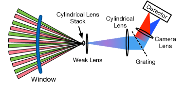
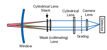
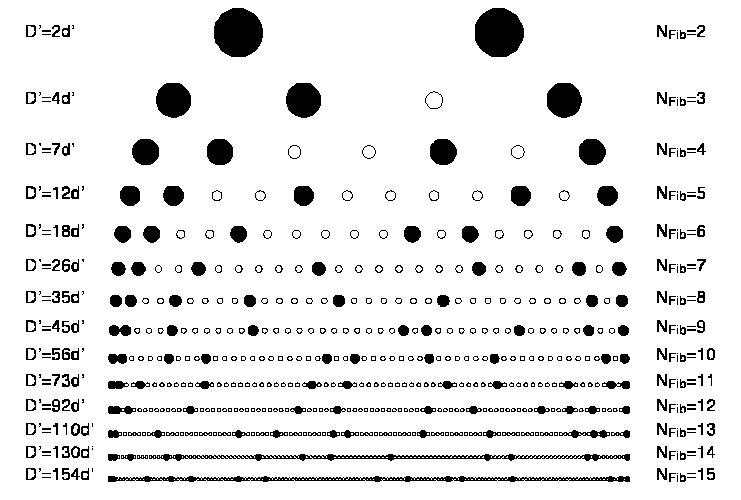
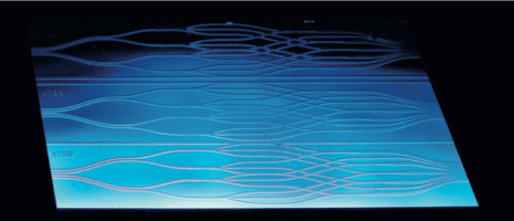
Existing or to-be-commissioned multi-telescope bulk optics beam combiners (e.g. AMBER [11] or MATISSE[12]) are of the all-in-one type, based on an architecture where a linear non-redundant array of beams is combined in a multi-axial geometry and dispersed in the orthogonal direction[13]. The multi-axial beam interference generates a spatial fringe pattern where the mutual coherence of each telescope pair is encoded in a unique spatial frequency, as a result of the non-redundant beam incidence angle selection. Multi-axial combiners necessarily requires cylindrical optics, with an anamorphic factor of order needed. A sketch of a 12-beam all-in-one multi-axial combiner is shown in Fig. 1. All-in-one multi- axial combiners have the advantage of adding no additional optics per beam when increasing the number of beams. However the linear length of the non-redundant array scales faster than (see following discussion on fibered beam combiners) and the diameter of the focusing optics required for fringe pattern generation could easily exceed 0.3-0.5 m for a PFI scenario. Because on-field experience has show that aberrations of the fringe imaging system substantially limit the performance of the multi-axial beam combiner, design and manufacturing of large aperture optical elements suitable for the beam combination task could be challenging.
Pupil plane, all-in-one multi-telescope beam combiners based on assemblies of multiple semi-reflecting mirrors have been used in the past to combine the beams at the COAST[14] and NPOI[15] interferometers. This beam combiner is very stable due to the absence of moving parts and is operated in temporal scanning mode. Proposed upgrades of this design to measure simultaneously visibilities of up to 6 telescopes featured however footprints in the order of 0.5 m2 (Baron et al. 2006[16], Buscher et al. 2008[17]), posing scaling constraints of the cold optics enclosure similar to the the multi-axial architecture in case a much larger number of telescopes are combined simultaneously. However, instruments combining simultaneously a relatively small number of telescopes can be used as partial combiners for larger arrays by cycling the combined telescope multiplets with a fast reconfigurable switchyard[16].
2.2 Direct imaging instruments
Conventional homodyne/heterodyne interferometric instruments measure the complex coherence function of electromagnetic fields, from which images of the astronomical target can be retrieved. The concept of pupil densification and the hyper-telescope [18] can be exploited to design an instrument forming the convolution of the object and a relatively compact point spread function (PSF) on the detector, which can be interpreted as an image of the object.
The densification process defines how an input pupil will be remapped into an output pupil that respects the overall telescope distribution (the inner pupil central positions are homothetic to the outer ones) but scales up the ratio between the output pupil diameters and the distances between pupils. The result of the pupil densification is a reduction of the ratio between the field of view of the reconstructed image and the interferometric PSF.
Lardiere et al. 2007[19] and Patru et al. 2007 [20] have explored how well different array architectures, i.e. input pupil distributions, can be densified. Their conclusions show that the choice of pupil distribution will lead to different field of views, angular resolution and halo level and therefore require a compromise based on the scientific goals. Additionally, it should be noted that projection effects caused by the source trajectory on the sky were not considered there, but could in principle be implemented.
Guided optics (whether fibers or 3D integrated optics) can be of great use to implement the densification of the input pupil since they simplify considerably the routing of light. Direct imaging and densification with fibers have already been explored experimentally by Patru et al. 2008 [21]. The scheme is easily scalable to an arbitrary large array of telescopes provided an accurate fringe tracking system for the whole array is available.
The key limitation of a direct imaging instrument is signal-to-noise in the case of a sparse (e.g. non-redundant) pupil. The fraction of the light in the central core is proportional to , where is the telescope diameter, the maximum baseline and and the magnification factors for telescope pupils and baselines respectively. For example, for a 9-telescope non-redundant array (Golay 1971[22]), this fraction is 0.36, or 0.326 once the geometric factor of circular pupils fitting in a hexagonal grid is taken into account. For background-limited direct imaging or imaging of faint structures around a bright star, the signal-to-noise is reduced by this factor. Recovering this signal-to-noise is possible by analysing the direct image with methods analogous to aperture-mask interferometry, however those techniques require . For the fields of view required for PFI, this either means another significant sensitivity loss with small , or an integral field unit, removing the simplicity of the direct imaging scheme and making the beam combiner similar to any other all-in-one combiner.
The strength of the direct imaging combiner architecture is in a redundant configuration, where the densified pupil is fully filled. This requires a much greater number of telescopes, where . This configuration would only be competitive if relatively small telescopes were very much more affordable than large ones[6].
2.3 Fibered beam combiners
The advantage of using optical fibers to perform efficient modal filtering and improve the precision of interferometric measurements by simultaneous photometric correction has been demonstrated long ago [23]. Two schemes of combination rely on the properties of fibered photonic components: 1) pairwise combiners based on fibre couplers [24], and 2) all-in-one multi-axial combiners [25]. Simple fibered 2x2 couplers operating in the H and K bands were used in pioneering photonic beam combiners such as FLUOR [24]. Experiments with L-band couplers were carried out [26], but have never been used in an instrument delivering science data. The pairwise combination scheme could be easily scaled up to multi-telescope arrays by means of a cascade of fiber couplers needed to distribute and combine simultaneously the starlight on all possible baselines. However, the main limitations of this approach are the problematic control of differential dispersion and the sensitivity of fibers to thermo-mechanical noise, which both grow with the total length of the fibre patches.
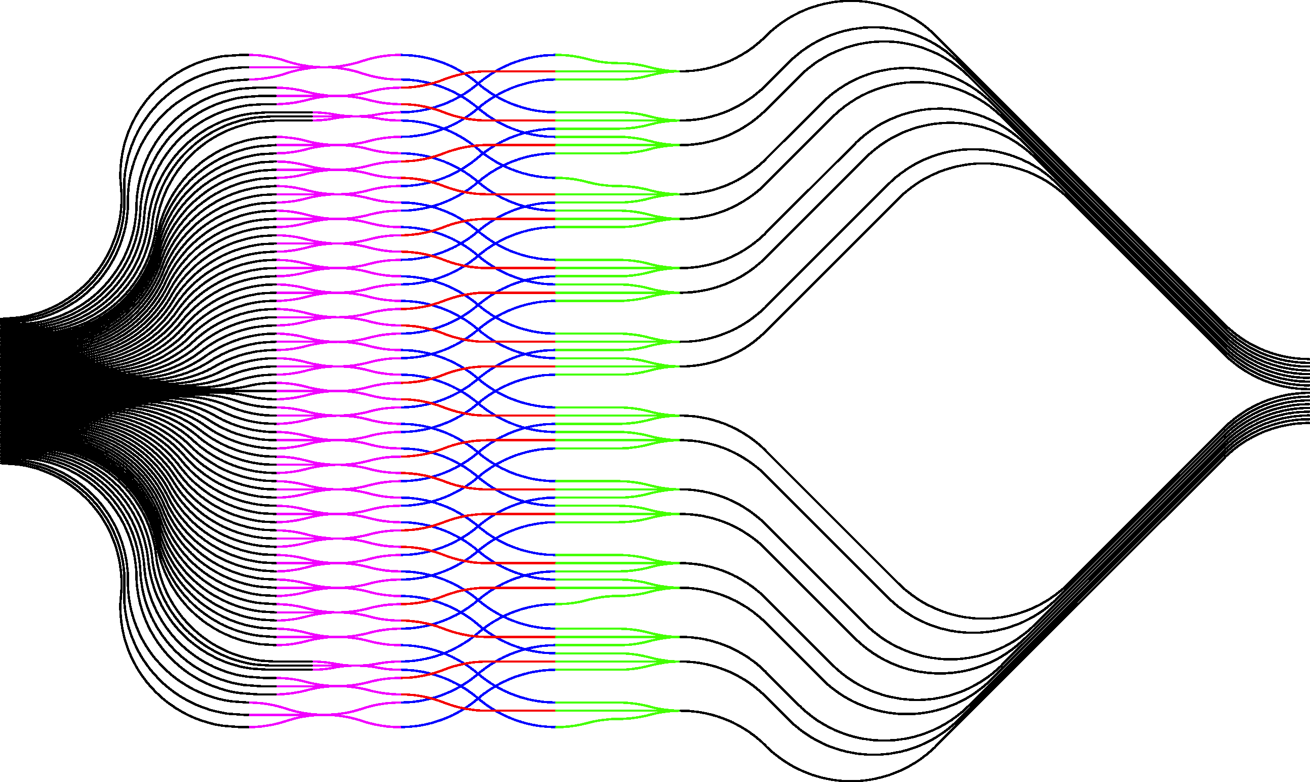
All-in-one, multi-axial, fibered beam combiners (see e.g. MIRC[25] and FIRST[27]) are in construction identical to their bulk-optics analogues, but use single mode optical fibers for modal filtering of the PSF of the telescopes and deliver the collected light to a V-groove, where the fiber-ends are arranged to form a non-redundant linear array. To date, up to 15 channels were successfully combined in the laboratory [28], and up to 9 were used on-sky in prototype instruments [27]. A non redundant configuration for 24 telescopes has been already calculated222D. Mozurkewich, personal communication.. As mentioned before, the physical length of the non-redundant array grows steeply as (see Fig. 2). Although the use of fibers and micro-optics can reduce considerably the size of the multi-axial combination scheme as compared to a bulk-optics design, a cryo-vacuum vessel of relatively large footprint is still needed to host the beam focusing optics.
A possible amelioration of the scheme is the arrangement of the fibers in a 2D non-redundant array[29]. This would result in a more compact optical arrangement, however the main difficultly would be the implementation of a cross-dispersion scheme, e.g. by means of a highly-spatially-resolved integral field unit sampling the fringes. A general limitation of fibered beam combiners is related to the long term phase drifts of thermo-mechanical origin, which can only be partially removed by closure phase techniques. A possible solution to this problem could be provided by rescaled versions of integrated optics pupil remappers, such as the Dragonfly instrument[30]. As discussed in the next paragraph, the resilience of integrated optical components to thermo-mechanical perturbations makes them inherently phase-stable. The technological challenge would mainly be related to cope with the dimension constraints imposed by the need of coupling many large-diameter, free-space input beams into the reformatting waveguides.
2.4 Integrated optics beam combiners
First proposed nearly 20 years ago by Malbet et al.[31], integrated optics (IO) beam combiners represent an effective and compact way to combine interferometrically the light collected by many telescopes. IO beam combiners leverage on the modal filtering properties of fibers/waveguides and an enhanced thermo-mechanical stability, due to the inherent rigidity of the IO component substrate. Miniaturization and absence of alignment degrees of freedom add up to the advantages of this technology. To date, several IO beam combiners have been proposed and/or tested in the laboratory and on-sky. Fig. 3 is an attempt to sort the various developed IO components according to the conventional classification scheme of the beam combiners outlined in the introduction.
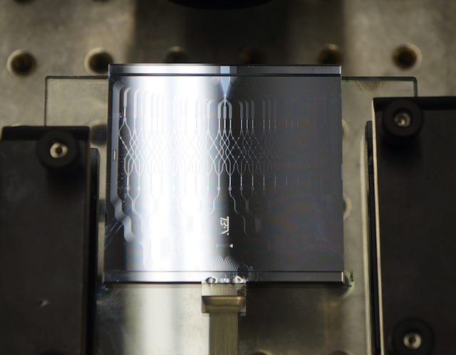
Pairwise planar IO beam combiners are the most developed devices so far, which have already been successfully tested on sky to combine simultaneously up to 4 telescopes both in temporal or matricial mode fringe encoding [32, 33, 34]. Additionally, a laboratory demonstration of a pairwise/spatial beam combiners was reported in Berger et al. 2000[35]. These components were operating in H- or K-band, leveraging on the high maturity of ion-indiffusion or silica-on-insulator planar IO technologies, which have been developed for telecom applications. Silica-on-insulator technology has been also used for manufacturing the partial/matricial beam combiner developed at the Observatoire de Paris Muedon, which combines simultaneously 18 channels over 32 selected baselines for the FIRST-IO instrument333S. Lacour, personal communication (see Figure 4). From the PFI perspective, conventional pairwise, planar-IO beam combiners measuring all baselines have limitations regarding the scalability to 1) a large number of telescopes, and 2) to mid-infrared wavelengths.
The scalability of planar IO pairwise beam combiners to a large number of telescopes is not easy mainly because of the 2D design constraints. To combine all baselines simultaneously, a large number of waveguide cross-overs are necessary, which could increase the channel cross-talk and reduces the SNR of the measured visibility, as compared to the performance of the ideal pairwise combiner. Even though the GRAVITY 4T beam combiner achieves cross-talks well below the 1% level, keeping the cross-talk low becomes more and more challenging as the number of combined telescopes increases. Moreover, planar IO pairwise combiners for mid-infrared wavelengths are still at a research development level as only very recently low propagation losses (0.3 dB/cm) were possible in waveguides manufactured by photolithographic techniques in chalcogenide materials.
In this respect, a promising avenue has been indicated by Rodenas et al. 2012[36], where the manufacturing of 3D-IO, 3-telescopes pairwise, mid-infrared beam combiner by means of Ultrafast Laser Inscription (ULI [37, 38]) in a chalcogenide glass was reported. ULI could potentially solve both the problem of cross- overs (resorting to 3D collision avoidance) and the scalability to longer wavelengths offering low propagation losses in mid-infrared-transparent materials (see also Section 4). Additionally, the manufacturing costs are much lower than conventional photolithographic methods.
With the exception of the already mentioned Dragonfly pupil remappper for multi-axial combination[30], existing all-in-one IO combination schemes have mostly been tested in the laboratory. Co-axial mixing of all input fields at the outputs of an integrated optical chip can be accomplished by means of a multimode interference coupler (MMI [39]) or by a periodic 2D array of evanescently coupled waveguides (the so called Discrete Beam Combiner - DBC[40]). The operation principle of both devices is similar, as multi-field interferograms are obtained at the output of the IO device from the interference of higher-order waveguide modes (MMI) or waveguide array supermodes (DBC). So far, MMI have been designed only in temporal scanning mode[39], but the matricial mode is also possible for MMI devices featuring at least outputs [9]. DBC have been tested in the lab both in matricial [41] and temporal scanning mode [42]. An interesting feature of MMI and DBC devices is that these devices can be designed to be intrinsically short and without waveguide bends, thus limiting the losses of the component to a bare minimum. A main drawback of these approaches is the strong chromatic response of the devices. However, experiments have shown that calibrated DBC operated in low-resolution spectro-interferometric mode () can be used over a typical astronomical bandwidth with fairly uniform performance[42] (SNR within 20% of best value across R-band). Scaling of DBC devices beyond 8 telescopes[43] is currently limited by the absence of an algorithm predicting the optimal design parameters of the combiner, forcing the use of direct numerical optimization algorithms, which scale factorially with the number of combined telescopes. However, these type of combiners could be used in partial combination schemes, as proposed in the DOMAC instrumental concept[44].
3 SENSITIVITY COMPARISON OF IDEAL MULTI-TELESCOPE COMBINERS
For PFI, the use of a sensitivity optimized beam combination architecture is of foremost importance to warrant high imaging performance at minimal infrastructure cost. In fact, the a major cost driver for large interferometric arrays are the telescopes, whose unit price notoriously scales harshly with the diameter[6], The overall performance of a beam combination scheme depends on three key elements, namely the intrinsic (ideal) sensitivity of its architecture, 2) the numerical stability of the coherence retrieval algorithm, and 3) the fabrication imperfections. The intrinsic sensitivity of the architecture can be roughly evaluated from the signal-to-noise ratio ( - defined as mean value over standard deviation) of a visibility measurement which, in the absence of thermal background, can be evaluated as[45]:
| (1) |
where is the visibility modulus, is the overall throughput of an individual beam combiner output, and is the number of photons collected by a single telescope during the interferometric measurement. The numerical stability of the coherence retrieval algorithm is crucial to avoid large errors in the determination of the complex visibilities from noisy interference data. While these two factors can be evaluated theoretically from basic principles, the impact of fabrication imperfections can be assessed only with comparative experimental tests on existing prototypes. Aim of this section is to derive the intrinsic sensitivity on the basis of a simple numerical model describing the three types of beam-combiner architectures, namely the non- redundant multi-axial array, the pairwise ABCD, and the DBC. While this analysis cannot give a definitive assessment of the performance of a realistic beam combiner, it nevertheless helps setting global loss margins for which a given architecture can perform better than another one.
The numerical model underlying our analysis is based on the ideal V2PM description of the analysed architectures [8] and a statistical model of the detection photon-shot-noise (detector read-out-noise is ignored, the approximation is equivalent to the so called ”photon-rich” detection regime). We also ignore the contribution of thermal background, as it strongly depends on contingent parameters of the telescope array and cold optics environment (see also Ireland et al. 2016[6]). The model is used in a Monte-Carlo simulation to extract expectation values of the of the fringe visibility amplitude for an unresolved target (), as a function of the detected flux per-telescope (assumed to be exactly equal for all telescopes). In each realisation step, the input field of each telescope is calculated as a constant amplitude multiplied by a random phase term. The input fields are fed to the V2PM of the beam combiner to derive the expected detected photon numbers at each of the output pixels of the instrument. A noise realisation with gaussian distribution and amplitude equal to the square root of the detected photon number is then added to the signal of each output pixel before retrieving the input coherences by applying the P2VM (Moore- Penrose pseudo-inverse of the V2PM). The coherences are then used to calculate the visibility amplitude for each baseline of the input array. From a statistics of the retrieved visibility amplitudes over all calculated realisations (in our case 1000), we could estimate the of each combiner architecture for a range of detected photons per-telescope.
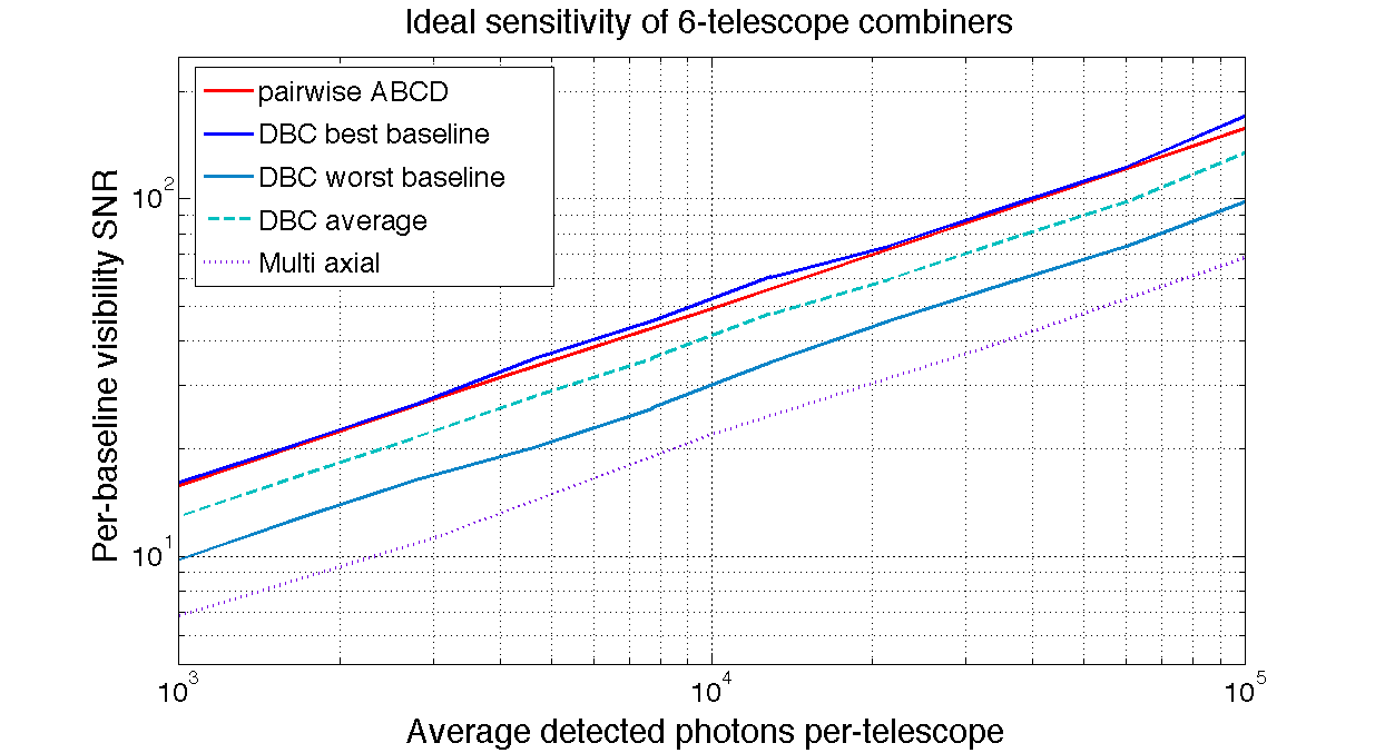
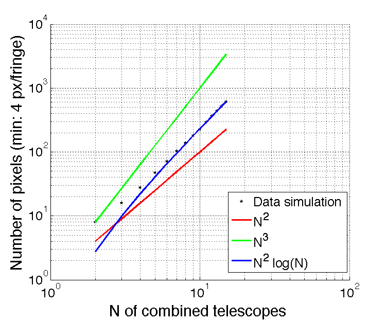
To allow a fair comparison between the three investigated architectures, we limited our simulations to the case of arrays composed by 6-telescopes, as it enabled the comparison of the largest set of combiners. The V2PM of the pairwise ABCD follows design of Benisty et al. 2009 [46] scaled up to 6-telescopes and includes 6 1x5 splitters with each output ending up in a 2-way 50/50 splitter, whose ends are connected by 2x2 50/50 directional couplers according to the required baselines combinations. Ideal phase shifts are assumed to generate the ABCD phase pattern, but no cross-over induced cross-talk between channels is modelled. The DBC design follows the indications of the optimal 6 telescope configuration identified for square waveguide arrays in Errmann&Minardi 2016[43] and which consists in an array of waveguides. The multi-axial combiner was modelled assuming the non-redundant configuration displayed in Fig. 2, a 4 pixel sampling for the fringes with the highest spatial frequency, and a window encompassing 2 full fringes at the smallest spatial frequency. A 5% photometric pick-off for each channel and a gaussian envelope of the individual beam with a waist 2.5 times smaller than the window were additionally assumed. Large variations of the design parameters of multi-axial scheme did not change qualitatively this picture ( variations % depending on design parameters). All simulations were carried out in the monochromatic approximation assuming that dispersive effects are negligible, e.g. because of dispersion control in the optical setup or sufficiently large spectral dispersion at the output of the device. Results of the simulations are displayed in Fig. 5. A comparison between the plots shows a qualitative difference between the three architectures. The first result is that the ABCD and DBC architectures offer a times better SNR than the multi-axial architecture for a given detected flux. Due to the scaling law of the SNR to the detected photon flux, this would mean that an ABCD/DBC component could be about 5-6 dB more lossy than the multi-axial scheme, and still perform better (loss margin). For combiners featuring the same global losses this is equivalent to a sensitivity gain of magnitudes ( magnitudes for the DBC in average) respect to a comparable multi-axial scheme. These results do not take into account covariances between visibility amplitudes, which mean that for a large number of baselines the uncertainty in measuring individual telescope photometry may have little influence on imaging signal-to-noise, despite causing correlated errors on individual baselines.
Interestingly, and differently from the other two investigated architectures, the DBC scheme features a baseline-dependent sensitivity. The best DBC baselines offer an 8% better SNR, while the worst ones a 35% lower compared to the ABCD scheme (the baseline averaged SNR of the DBC is only 20% lower than ABCD). This feature may find an application in the optimisation of the telescope array combination configuration for the improvement of the fidelity of interferometric image reconstruction. Since our simulations show that the SNR scales linearly with the visibility amplitude of the measured baseline, the beam combiner inputs could be arranged to be associated long baselines (which could in general resolve the target) to the most performant combination channel, while the short baselines (for which the target is unresolved) would be associated to the less performant combination channel. In fact, this configuration would give as a result a more uniform visibility SNR across the sampled (u,v) plane, which could potentially impact the quality of the reconstructed interferometric image.
4 TECHNOLOGICAL PLATFORMS FOR MID-INFRARED PHOTONICS
In this section we review the raw materials and fabrication technologies for fibres and integrated optics suitable for both bulk and photonic mid-infrared beam combination instruments.
Materials
The PFI science case will require optical instruments operating over a very broad wavelength range extending from 3 to 30 m. This is significantly larger than the near-IR range and in principle more difficult to cover with one single material or technology. The availability of transparent materials encompassing the mid-infrared range is large and diverse. Suitable materials are typically expected to have good chemical and mechanical stability, excellent intrinsic transparency, low toxicity, a temperature working range compatible with cryogenic operations, relatively low index of refraction to minimise the Fresnel losses, limited birefringence for passive functions, no excessive fragility and low ageing. In some cases they need to be suitable for thin film deposition by sputtering or photo-evaporation when lithography or etching process are to be implemented. In most cases, they need to be suitable for the manufacturing of rather small cross-section waveguides if single-mode operation is sought. Depending on the application and spectral range, materials that have already been used for mid-IR photonics are:
-
•
Niobate Lithium presents also some interest in particular for high-frequency active functions. However the competitiveness of this glass in terms of transparency for wavelengths larger than 2.5 microns does not appear very promising.
-
•
2.5–4 m: Fluoride glasses were thought for long to be the “gold mine” for mid-IR photonics and optical fibres with theoretical intrinsic losses down to 0.001 - 0.01dB/ km. In reality losses are closer to dB/km, mainly because of the presence of numerous scattering centres due to impurities in the fabrication process. Fuoride glasses remain very competitive solutions for operation below 4 m.
-
•
For wavelengths up to 10 m, chalcogenide glasses have shown to be a solution with constantly increasing reliability and promises[47]. Initially considered as difficult glasses to work with, they have reached commercial maturity and are available under non-toxic form to fabricate for instance mid-IR lenses and fibres (e.g. with BD-1 and BD-2 glasses). The transparency is excellent, although comparable issues to fluoride glasses may arise due to the presence of impurities and scattering centres.
-
•
Covering wavelengths longer than 10 microns can be done in principle with telluride-doped glasses or silver-halide glasses. Experimental evidence has been shown by Vigreux et al. 2011[48]. However the intrinsic transparency seems low.
-
•
In the 20 to 30 microns range, silicon- and germanium-based ”far-infrared” waveguides are proposed on a theoretical basis but have not been, to the best of our knowledge, investigated for astronomy (Soref et al. 2006[49] and references therein).
Fibers
The availability of mid-infrared fibres is a major aspect for the application of mid-IR photonics to astronomical instrumentation. In particular for stellar interferometry a fibered interface between the telescopes and the recombination unit has proven to be a reliable solution to obtain a workable instrument. In general the use of fibres allows a simplification of the general optical design of the instrument.
Significant progress has been achieved in the last years, which led to the industrial maturity of a number of fibre solutions.
-
•
2–5 microns single-mode Zirconium/Indium fluoride fibres with 0.2 dB/m losses are commercially available at a competitive price. In the OHANA experiment[50], customized fibers with dB/km losses were fabricated. These fibres appear as the prime solution to cover the K, L and M astronomical bands.
-
•
Chalcogenide commercial fibres up to 9 microns, SM and MM, with different level of dB/m losses. Multimodes up to 9 microns transparency achieve 0.2 dB/m as well. Very recently, chalcogenide polarisation maintaining fibres with losses below 0.5 dB/m in the mid-infrared here manufactured [51].
-
•
Large-core hollow-core ( mm) multimode fibres for 10 microns light transport commercially available with 0.1 dB/m and zero dispersion.
-
•
Very low-loss research grade micro-structured fibres with 0.3 to 0.03 dB/m in the L band [52].
Mid-infrared integrated optics
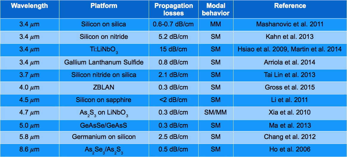
Planar and 3D IO manufacturing processes suitable for MIR wavelengths are still in a development phase, and do not currently offer the quality of silica based micro fabrication. In Table 6 a non-exhaustive list of some of the leading results that have been achieved in the L, M and N bands is presented. Only very recently a few technology platforms achieved sub-dB/cm propagation losses in the mid-IR. But low propagation losses are only one of the requirements for a useful beam combination technology. It will, for example, be essential to realise integrated components that utilise low cross-talk waveguide crossings and high quality beam splitters that are ideally achromatic, and that are suitable for efficient coupling to mid-IR transmitting fibres. Here we highlight a few technologies which have already been considered for applications to stellar interferometry:
- •
-
•
(CW- and ultrafast) laser writing is a recent but promising technique relying on the use of ultrashort laser pulses to directly inscribe three-dimensional waveguide structures inside a transparent glass substrate. Ultrafast laser writing provides the ability to fabricate waveguide crossings with zero cross-talk and beam combiners based on two- dimensional arrays of coupled waveguides (DBC, see previous section). Two- and three-telescope structures have been successfully realised for mid-infrared (Labadie et al. 2011[55], [36]; Arriola et al. 2014[56], Gross et al. 2015[57], Tepper et al. 2016[58]). Low propagation losses in the order of 0.2 dB/cm have also been reported in ZBLAN[57] and GLS444R.R. Thomson, personal communication. A current limitation of the method is the generation of a remarkable, long-range stress-birefringence (see Diener et al. 2016[59]), which could constrain the realisation of complex 3D photonic structures.
-
•
Ion-exchange and diffusion in glasses. This platform has been very successful in the telecommunication range and is at use for the visible in astronomy. It has been applied at longer wavelength in Germanate glasses. Channel waveguides for the mid-IR have been fabricated but only tested at 1.5 m [60]. 2-telescope and 3-telescope Ti:diffusion Niobate Lithium combiners for the L band have been also fabricated with this platform [61, 62].
5 TECHNOLOGICAL CHALLENGES
Our review of beam combination schemes and fabrication technologies lead us to identify several technological challenges which need to be overcome in order to enable efficient mid-infrared, multi-telescope beam combination schemes suitable for PFI. We can distinguish two main challenges, which relate to the identification of 1) the beam combination architecture and, 2) the technological approach.
The first challenge is to select the best beam combination architecture for a given interferometric array. The solution to this problem include both array architecture and image reconstruction considerations and couples to the choice of a suitable technological platform and beam combination scheme for science and fringe tracking. From the respective of the beam combination instrument, the main choice is between a scheme allowing the combination of all possible baselines or a sub-set of them (e.g. for efficient fringe tracking). The imaging capabilities of the array could depend from a trade-off between the number of baselines and the of visibility measurements on individual baselines. The combination of a sub-set of baselines could increase the at the expense of (u,v) plane coverage, thus a compromise has to be found. This choice should be also confronted with the technical feasibility of an instrument suitable for the combination of all baselines. As we have seen in Section 2, the scalability of existing beam combination schemes up to telescopes is not trivial, due to the rapidly increasing complexity of fabrication constraints.
A further challenge is to understand which technological approach (bulk optics or photonic) could deliver the best interferometric performance in terms of sensitivity and precision. Given that the PFI design assumes adaptive optics correction for all telescopes, modal filtering may not be required anymore for the achievement of high precision visibility measurements, as long as high order aberration correction is available.
In this respect, bulk optics combiners could exhibit a better throughput than photonic ones, as the coupling efficiency into a single mode waveguide of the PSF of an aberration-free telescope with circular pupil cannot be greater than 80% [63]. However, very recent advance in micro-structured fibres demonstrated that coupling efficiencies of up to 93.7% could be achieved for beams shaped as ideal PSF of a telescope with circular aperture[64].
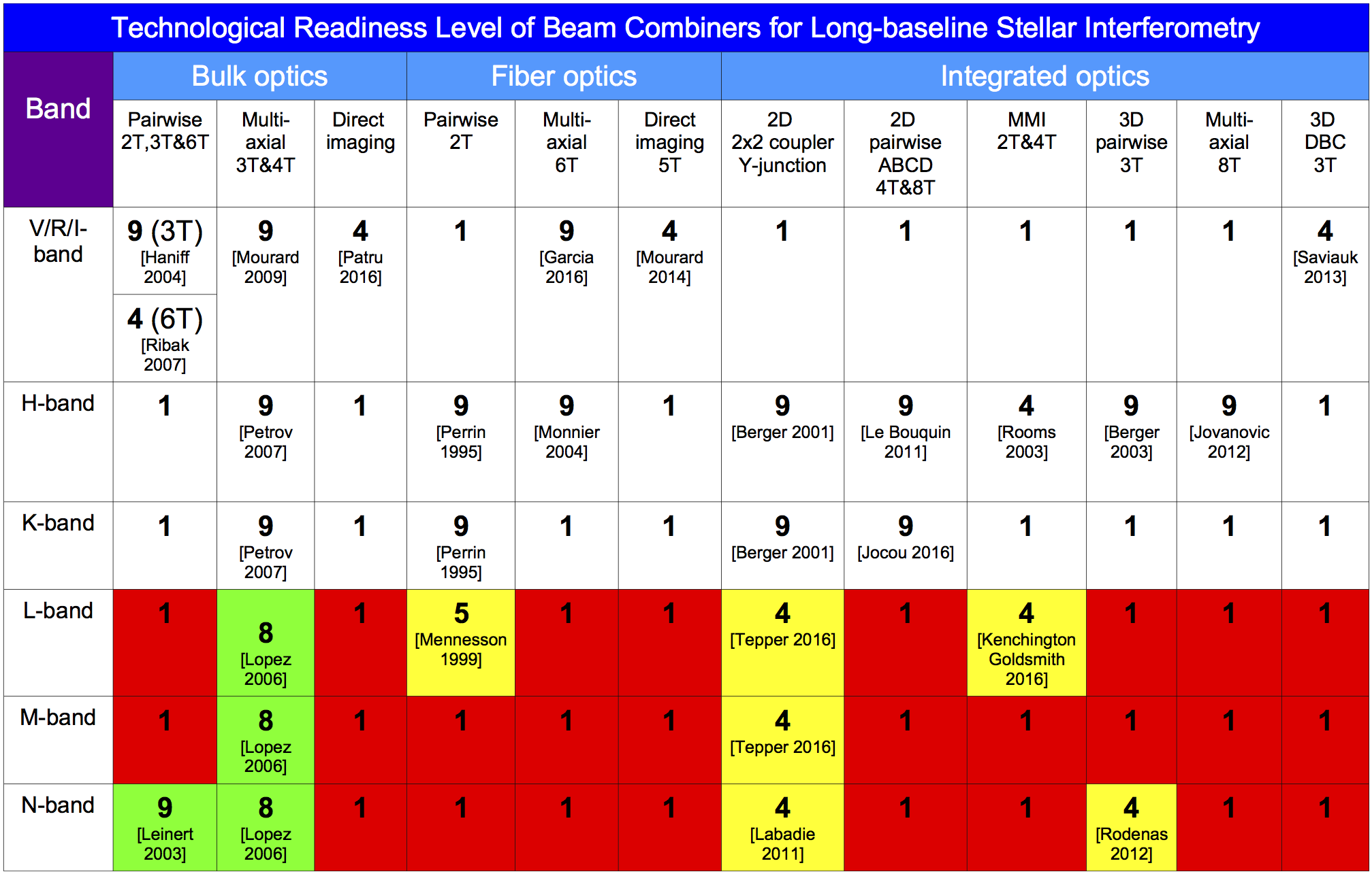
In the short term, a further advantage of bulk optics solutions for the mid-infrared is that this technology has already been tested on sky, as indicated in Fig. 7, where we attempted to the list the Technological Readiness Level (TRL[65]) of V2 beam combiners for stellar interferometry, sorted by operating astronomical band and technology is shown.
Even though photonic beam combiners for mid-infrared have reached at most the level of laboratory demonstration, integrated optics solutions are in a good position to reach soon the level of on-sky test for a moderate number of combined telescopes (e.g. ), considering the recent successful laboratory test of building blocks like 2x2 couplers [57, 58], pairwise 3-telescope combiners[36] and the reported on-sky test of a two apertures mid-infrared nuller[66].
Nonetheless, current critical points of photonic combiners are the propagation losses and the polarisation state control, which require further R&D .
In this context, the recent achievement of mid-infrared waveguides with propagation losses in the order of 0.2 dB/cm makes ultrafast laser inscription a very promising technological platform for the manufacturing of mid-infrared IO components, offering also very low production costs as compared to photolithographic processes. A current limitation of the ULI technique is however the low achievable index contrast (from to depending on the substrate material), which imposes large curvature radii for bended waveguides in order to suppress radiation losses. This translates in very elongated IO components which could result in beam combiner lengths of the order of several centimetres, implying both a higher impact of intrinsic losses and more difficult control of the optical path difference in the manufactured component. Additionally, the long range (m) tensile stresses induced in the substrate by the ULI [59], could make the control of the transverse uniformity and birefringence of complex waveguide circuits rather tricky.
6 CONCLUSIONS AND RECOMMENDATIONS
As outlined in this paper, several competing beam combination and related technological solutions are available or will soon be available to meet the requirements of the beam combination instruments at the PFI facility, all of them entailing design and/or technological challenges which require further R&D.
Concerning the fringe tracker beam combination scheme, near-infrared fringe measurement on a selection of short/intermediate baselines is required. Some level of redundancy in the combination scheme will be necessary to limit the impact of failure of fringe tracking on individual baselines. As for the fringe tracker instrument, we believe that near-infrared IO will play a central role in delivering a stable and compact device with high throughput. As mentioned before, planar IO in near-infrared is already technologically mature to deliver such baselines-selective beam combiners. Additionally, ultrafast laser inscription could be used to avoid cross-overs in the beam combination scheme and thus limit the cross-talk between the combined channels.
Design challenges for the science combiner are mainly related to the identification of the best combination architecture (partial or full baseline coverage) compromising between and (u,v) plane coverage which could enable high-fidelity and high-dynamic-range images for the generic PFI target. This first decision will influence the final choice of the type of beam combination instrument which will be eventually adopted by PFI. Additionally, the design of a compact and mostly maintenance-free cold optics setup is also an issue to reduce the financial investment and operation costs of the instrument.
As discussed on Section 3, fundamental properties of the beam combiner architecture and related coherence retrieval algorithm make pairwise ABCD and all-in-one DBC schemes intrinsically more sensitive than a multi-axial all-in-one solution by about 1.5 magnitudes. Because the costs of the telescopes is the main driver of the overall PFI facility [6], essentially more sensitive schemes are in principle best candidates for the beam combination instrument. We warn however that technological/manufacturing issues like e.g. the overall beam combiner transmission, scalability to large arrays of telescopes, conditioning of the V2PM, polarisation and intrinsic chromatic dispersion of the beam combiners can have a more determinant role in setting the sensitivity of the final beam combination instrument. In this context, the direction of future developments of photonic technologies for the mid-infrared will be also a crucial ingredient for the choice of a suitable beam combination scheme and relative manufacturing technology.
As from the current stand of the technological development, we mention that a full-baseline coverage for a 21 telescopes array would be a very challenging task for any of the discussed beam combination schemes or technologies. Partial beam combination schemes by means of replication or temporal multiplexing of intermediate size beam combiners (e.g. for ) could represent a practical solution, at least in the short term.
Acknowledgements.
S.M. and L.L. acknowledge the financial support of the German Ministry of Research and Education (BMBF) under grant ”ALSI - Advanced Laser-writing for Stellar Interferometry”. (05A14SJA).References
- [1] Monnier, J. D., Kraus, S., Buscher, D., Berger, J.-P., Haniff, C., Ireland, M., Labadie, L., Lacour, S., Le Coroller, H., Petrov, R. G., Pott, J.-U., Ridgway, S., Surdej, J., ten Brummelaar, T., Tuthill, P., and van Belle, G., “Planet formation imager (PFI): introduction and technical considerations,” in [Optical and Infrared Interferometry IV ], Proc. SPIE 9146, 914610 (July 2014).
- [2] Monnier, J. D., Ireland, M. J., Kraus, S., Baron, F., Creech-Eakman, M., Dong, R., Isella, A., Merand, A., Michael, E., Minardi, S., Mozurkewich, D., Petrov, R., Rinehard, S., ten Brummelaar, T., Vasisht, G., Wishnow, E., Young, J., and Zhu, Z., “Architecture design study and technology roadmap for the Planet Formation Imager (PFI),” ArXiv e-prints (Aug. 2016).
- [3] Ireland, M. J., Monnier, J. D., Kraus, S., Isella, A., Minardi, S., Petrov, R., ten Brummelaar, T., Young, J., Vasisht, G., Mozurkewich, D., Rinehart, S., Michael, E. A., van Belle, G., and Woillez, J., “Status of the Planet Formation Imager (PFI) concept,” ArXiv e-prints (Aug. 2016).
- [4] Kraus, S., Monnier, J., Harries, T., Dong, R., Bate, M., Whitney, B., Zhu, Z., Buscher, D., Berger, J.-P., Haniff, C., Ireland, M., Labadie, L., Lacour, S., Petrov, R., Ridgway, S., Surdej, J., ten Brummelaar, T., Tuthill, P., and van Belle, G., “The science case for the Planet Formation Imager (PFI),” in [Optical and Infrared Interferometry IV ], Proc. SPIE 9146, 914611 (July 2014).
- [5] Kraus, S., Monnier, J. D., Ireland, M. J., Duchene, G., Espaillat, C., Hoenig, S., Juhasz, A., Mordasini, C., Olofsson, J., Paladini, C., Stassun, K., Turner, N., Vasisht, G., Harries, T. J., Bate, M. R., Gonzalez, J.-F., Matter, A., Zhu, Z., Panic, O., Regaly, Z., Morbidelli, A., Meru, F., Wolf, S., Ilee, J., Berger, J.-P., Zhao, M., Kral, Q., Morlok, A., Bonsor, A., Ciardi, D., Kane, S. R., Kratter, K., Laughlin, G., Pepper, J., Raymond, S., Labadie, L., Nelson, R. P., Weigelt, G., ten Brummelaar, T., Pierens, A., Oudmaijer, R., Kley, W., Pope, B., Jensen, E. L. N., Bayo, A., Smith, M., Boyajian, T., Quiroga-Nunez, L. H., Millan-Gabet, R., Chiavassa, A., Gallenne, A., Reynold, M., de Wit, W.-J., Wittkowski, M., Millour, F., Gandhi, P., Ramos Almeida, C., Alonso Herrero, A., Packham, C., Kishimoto, M., Tristram, K. R. W., Pott, J.-U., Surdej, J., Buscher, D., Haniff, C., Lacour, S., Petrov, R., Ridgway, S., Tuthill, P., van Belle, G., Armitage, P., Baruteau, C., Benisty, M., Bitsch, B., Paardekooper, S.-J., Pinte, C., Masset, F., and Rosotti, G. P., “Planet Formation Imager (PFI): science vision and key requirements,” ArXiv e-prints (Aug. 2016).
- [6] Ireland, M. J., Monnier, J. D., Kraus, S., Isella, A., Minardi, S., Petrov, R., ten Brummelaar, T., Young, J., Vasisht, G., Mozurkewich, D., and Rinehard, S., “Status of the Planet Formation Imager (PFI) concept,” Proc. SPIE 9907, 9907–55 (2016).
- [7] Ireland, M. J. and Monnier, J. D., “A dispersed heterodyne design for the planet formation imager,” in [Optical and Infrared Interferometry IV ], Proc. SPIE 9146, 914612 (July 2014).
- [8] Tatulli, E., Millour, F., Chelli, A., Duvert, G., Acke, B., Utrera, O. H., Hofmann, K.-H., Kraus, S., Malbet, F., Mège, P., Petrov, R., Vannier, M., Zins, G., Antonelli, P., Beckmann, U., Bresson, Y., Dugué, M., Gennari, S., Glück, L., Kern, P., Lagarde, S., Coarer, E. L., Lisi, F., Perraut, K., Puget, P., Rantakyrö, F., Robbe-Dubois, S., Roussel, A., Weigelt, G., Accardo, M., Agabi, K., Altariba, E., Arezki, B., Aristidi, E., Baffa, C., Behrend, J., Blöcker, T., Bonhomme, S., Busoni, S., Cassaing, F., Clausse, J.-M., Colin, J., Connot, C., Delboulbé, A., de Souza, A. D., Driebe, T., Feautrier, P., Ferruzzi, D., Forveille, T., Fossat, E., Foy, R., Fraix-Burnet, D., Gallardo, A., Giani, E., Gil, C., Glentzlin, A., Heiden, M., Heininger, M., Kamm, D., Kiekebusch, M., Contel, D. L., Contel, J.-M. L., Lesourd, T., Lopez, B., Lopez, M., Magnard, Y., Marconi, A., Mars, G., Martinot-Lagarde, G., Mathias, P., Monin, J.-L., Mouillet, D., Mourard, D., Nussbaum, E., Ohnaka, K., Pacheco, J., Perrier, C., Rabbia, Y., Rebattu, S., Reynaud, F., Richichi, A., Robini, A., Sacchettini, M., Schertl, D., Schöller, M., Solscheid, W., Spang, A., Stee, P., Stefanini, P., Tallon, M., Tallon-Bosc, I., Tasso, D., Testi, L., Vakili, F., von der Lühe, O., Valtier, J.-C., and Ventura, N., “Interferometric data reduction with amber/vlti. principle, estimators and illustration,” A&A 464, 29–42 (2007).
- [9] Le Bouquin, J.-B. J., Berger, J.-P., Labeye, P. R., Tatulli, E., Malbet, F., Rousselet-Perraut, K., and Kern, P. Y., “Comparison of integrated optics concepts for a near-infrared multi-telescope beam combiner,” in [New Frontiers in Stellar Interferometry ], Traub, W. A., ed., Proc. SPIE 5491, 1362 (Oct. 2004).
- [10] Ribak, E. N., Gai, M., Loreggia, D., and Lipson, S. G., “Simple beam combination for stellar interferometry,” Opt. Lett. 32, 1075–1077 (May 2007).
- [11] Petrov, R. G., Malbet, F., Weigelt, G., Antonelli, P., Beckmann, U., Bresson, Y., Chelli, A., Dugué, M., Duvert, G., Gennari, S., Glück, L., Kern, P., Lagarde, S., Le Coarer, E., Lisi, F., Millour, F., Perraut, K., Puget, P., Rantakyrö, F., Robbe-Dubois, S., Roussel, A., Salinari, P., Tatulli, E., Zins, G., Accardo, M., Acke, B., Agabi, K., Altariba, E., Arezki, B., Aristidi, E., Baffa, C., Behrend, J., Blöcker, T., Bonhomme, S., Busoni, S., Cassaing, F., Clausse, J.-M., Colin, J., Connot, C., Delboulbé, A., Domiciano de Souza, A., Driebe, T., Feautrier, P., Ferruzzi, D., Forveille, T., Fossat, E., Foy, R., Fraix-Burnet, D., Gallardo, A., Giani, E., Gil, C., Glentzlin, A., Heiden, M., Heininger, M., Hernandez Utrera, O., Hofmann, K.-H., Kamm, D., Kiekebusch, M., Kraus, S., Le Contel, D., Le Contel, J.-M., Lesourd, T., Lopez, B., Lopez, M., Magnard, Y., Marconi, A., Mars, G., Martinot-Lagarde, G., Mathias, P., Mège, P., Monin, J.-L., Mouillet, D., Mourard, D., Nussbaum, E., Ohnaka, K., Pacheco, J., Perrier, C., Rabbia, Y., Rebattu, S., Reynaud, F., Richichi, A., Robini, A., Sacchettini, M., Schertl, D., Schöller, M., Solscheid, W., Spang, A., Stee, P., Stefanini, P., Tallon, M., Tallon-Bosc, I., Tasso, D., Testi, L., Vakili, F., von der Lühe, O., Valtier, J.-C., Vannier, M., and Ventura, N., “AMBER, the near-infrared spectro-interferometric three-telescope VLTI instrument,” A&A 464, 1–12 (Mar. 2007).
- [12] Lopez, B., Wolf, S., Lagarde, S., Abraham, P., Antonelli, P., Augereau, J. C., Beckman, U., Behrend, J., Berruyer, N., Bresson, Y., Chesneau, O., Clausse, J. M., Connot, C., Demyk, K., Danchi, W. C., Dugué, M., Flament, S., Glazenborg, A., Graser, U., Henning, T., Hofmann, K. H., Heininger, M., Hugues, Y., Jaffe, W., Jankov, S., Kraus, S., Laun, W., Leinert, C., Linz, H., Mathias, P., Meisenheimer, K., Matter, A., Menut, J. L., Millour, F., Neumann, U., Nussbaum, E., Niedzielski, A., Mosonic, L., Petrov, R., Ratzka, T., Robbe-Dubois, S., Roussel, A., Schertl, D., Schmider, F.-X., Stecklum, B., Thiebaut, E., Vakili, F., Wagner, K., Waters, L. B. F. M., and Weigelt, G., “MATISSE: perspective of imaging in the mid-infrared at the VLTI,” in [Society of Photo-Optical Instrumentation Engineers (SPIE) Conference Series ], Proc. SPIE 6268, 0 (June 2006).
- [13] Bedding, T. R., Robertson, J. G., and Marson, R. G., “An optical interferometer with wavelength dispersion.,” A&A 290 (Oct. 1994).
- [14] Haniff, C. A., Baldwin, J. E., Basden, A. G., Bharmal, N. A., Boysen, R. C., Buscher, D. F., Keen, J. W., Mackay, C. D., O’Donovan, B., Seneta, E. B., Thorsteinsson, H., Thureau, N. D., Tubbs, R. N., Warner, P. J., Wilson, D. M., and Young, J. S., “COAST: recent technology and developments,” in [New Frontiers in Stellar Interferometry ], Traub, W. A., ed., Proc. SPIE 5491, 511 (Oct. 2004).
- [15] Armstrong, J. T., Mozurkewich, D., Rickard, L. J., Hutter, D. J., Benson, J. A., Bowers, P. F., Elias, II, N. M., Hummel, C. A., Johnston, K. J., Buscher, D. F., Clark, III, J. H., Ha, L., Ling, L.-C., White, N. M., and Simon, R. S., “The Navy Prototype Optical Interferometer,” Astrph. J. 496, 550–571 (Mar. 1998).
- [16] Baron, F., Buscher, D. F., Coyne, J., Creech-Eakman, M. J., Haniff, C. A., Jurgenson, C. A., and Young, J. S., “Beam combiner studies for the Magdalena Ridge Observatory Interferometer,” in [Society of Photo-Optical Instrumentation Engineers (SPIE) Conference Series ], Proc. SPIE 6268, 62681R (June 2006).
- [17] Buscher, D., Baron, F., Coyne, J., Haniff, C., and Young, J., “BOBCAT - A Photon-efficient Multi-way Combiner for the VLTI,” in [The Power of Optical/IR Interferometry: Recent Scientific Results and 2nd Generation ], Richichi, A., Delplancke, F., Paresce, F., and Chelli, A., eds., 407 (2008).
- [18] Labeyrie, A., “Resolved imaging of extra-solar planets with future 10-100km optical interferometric arrays.,” A&A Suppl. Ser. 118, 517–524 (Sept. 1996).
- [19] Lardière, O., Martinache, F., and Patru, F., “Direct imaging with highly diluted apertures - I. Field-of-view limitations,” Month. Not. R. Astr. Soc. 375, 977–988 (Mar. 2007).
- [20] Patru, F., Mourard, D., Lardière, O., and Lagarde, S., “Optimization of the direct imaging properties of an optical-fibred long baseline interferometer,” Month. Not. R. Astr. Soc. 376, 1047–1053 (Apr. 2007).
- [21] Patru, F., Mourard, D., Clausse, J.-M., Delage, L., Reynaud, F., Dubreuil, M., Bonneau, D., Bosio, S., Bresson, Y., Hugues, Y., Lardière, O., and Roussel, A., “First results from a laboratory hypertelescope using single-mode fibers,” A&A 477, 345–352 (Jan. 2008).
- [22] Golay, M. J. E., “Point arrays having compact, nonredundant autocorrelations,” J. Opt. Soc. Am. 61, 272–273 (Feb 1971).
- [23] Coudé du Foresto, V., Ridgway, S., and Mariotti, J.-M., “Deriving object visibilities from interferograms obtained with a fiber stellar interferometer,” A&A Supp. Ser. 121 (Feb. 1997).
- [24] Perrin, G., Coudé du Foresto, V., Ridgway, S. T., Mariotti, J.-M., and Benson, J. A., “Fibered recombination unit for the Infrared-Optical Telescope Array,” in [Fiber Optics in Astronomical Applications ], Barden, S. C., ed., Proc. SPIE 2476, 120–128 (June 1995).
- [25] Monnier, J. D., Berger, J.-P., Millan-Gabet, R., and ten Brummelaar, T. A., “The michigan infrared combiner (mirc): Ir imaging with the chara array,” in [Proc. SPIE ], 5491, 1370–1379 (2004).
- [26] Mennesson, B., Mariotti, J. M., Coudé du Foresto, V., Perrin, G., Ridgway, S., Ruilier, C., Traub, W. A., Carleton, N. P., Lacasse, M. G., and Mazé, G., “Thermal infrared stellar interferometry using single-mode guided optics: first results with the TISIS experiment on IOTA,” A&A 346, 181–189 (June 1999).
- [27] Huby, E., Perrin, G., Marchis, F., Lacour, S., Kotani, T., Duchêne, G., Choquet, E., Gates, E. L., Woillez, J. M., Lai, O., Fédou, P., Collin, C., Chapron, F., Arslanyan, V., and Burns, K. J., “First, a fibered aperture masking instrument i. first on-sky test results,” A&A 541, A55 (2012).
- [28] Mozurkewich, D. and Traore, A., “Beam combination with a large number of apertures,” in [Optical and Infrared Interferometry II ], Proc. SPIE 7734, 773443 (July 2010).
- [29] Lacour, S., Imagerie des étoiles évoluées par interférométrie. Réarrangement de pupille, PhD thesis, PhD Thesis, 2010 (2010).
- [30] Jovanovic, N., Tuthill, P. G., Norris, B., Gross, S., Stewart, P., Charles, N., Lacour, S., Ams, M., Lawrence, J. S., Lehmann, A., Niel, C., Robertson, J. G., Marshall, G. D., Ireland, M., Fuerbach, A., and Withford, M. J., “Starlight demonstration of the Dragonfly instrument: an integrated photonic pupil-remapping interferometer for high-contrast imaging,” Month. Not. R. Astr. Soc. 427, 806–815 (Nov. 2012).
- [31] Malbet, F., Kern, P., Schanen-Duport, I., Berger, J.-P., Rousselet-Perraut, K., and Benech, P., “Integrated optics for astronomical interferometry,” A&A Suppl. Ser. 138, 135–145 (1999).
- [32] Berger, J. P., Haguenauer, P., Kern, P., Perraut, K., Malbet, F., Schanen, I., Severi, M., Millan-Gabet, R., and Traub, W., “Integrated optics for astronomical interferometry. IV. First measurements of stars,” A&A 376, L31–L34 (Sept. 2001).
- [33] Berger, J.-P., Hagenauer, P., Kern, P., Perraut, K., Malbet, F., Gluck, S., Lagny, L., Schanen, I., Laurent, E., Delboulbe, A., Magnard, Y., Tatulli, E., Traub, W., Carleton, N., Millan-Gabet, R., Monnier, J. D., and Pedretti, E., “An integrated-optics 3-way beam combiner for iota,” in [Proc. SPIE ], 4838, 1099–1106 (2003).
- [34] Bouquin, J.-B. L., Berger, J.-P., Lazareff, B., Zins, G., Haguenauer, P., Jocou, L., Kern, P., Millan-Gabet, R., Traub, W., Absil, O., Augereau, J.-C., Benisty, M., Blind, N., Bonfils, X., Bourget, P., Delboulbe, A., Feautrier, P., M.Germain, Gitton, P., Gillier, D., Kiekebusch, M., Kluska, J., Knudstrup, J., Labeye, P., Lizon, J.-L., Monin, J.-L., Magnard, Y., Malbet, F., Maurel, D., Ménard, F., Micallef, M., Michaud, L., Montagnier, G., Morel, S., Moulin, T., Perraut, K., Popovic, D., Rabou, P., Rochat, S., Rojas, C., Roussel, F., Roux, A., Stadler, E., Stefl, S., Tatulli, E., and Ventura, N., “Pionier: a 4-telescope visitor instrument at vlti,” A&A 535, A67 (2011).
- [35] Berger, J.-P., Benech, P., Schanen-Duport, I., Maury, G., Malbet, F., and Reynaud, F., “Combining up to eight telescope beams in a single chip,” in [Proc. SPIE ], 4006, 986–995 (2000).
- [36] Rodenas, A., Martin, G., Arzeki, B., Psaila, N. D., Jose, G., Jha, A., Labadie, L., Kern, P., Kar, A. K., and Thomson, R. R., “Three-dimensional mid-infrared photonic circuits in chalcogenide glass,” Opt. Lett. 37, 392–394 (2012).
- [37] Nolte, S., Will, M., Burghoff, J., and Tünnermann, A., “Ultrafast laser processing: new options for three-dimensional photonic structures,” J. Mod. Opt. 51, 2533–2542 (2004).
- [38] Thomson, R. R., Kar, A. K., and Allington-Smith, J., “Ultrafast laser inscription: an enabling technology for astrophotonics,” Optics Express 17, 1963–1969 (Feb. 2009).
- [39] Rooms, F., Morand, A., Schanen-Duport, I., Broquin, J.-E., Haguenauer, P., Berger, J.-P., Martin, M., and Benyattou, T., “New concept for combining three telescopes with integrated optics: multi-mode interferences (MMI),” in [Interferometry for Optical Astronomy II ], Traub, W. A., ed., Society of Photo-Optical Instrumentation Engineers (SPIE) Conference Series 4838, 1359–1369 (Feb. 2003).
- [40] Minardi, S. and Pertsch, T., “Interferometric beam combination with discrete optics,” Opt. Lett. 35, 3009–3011 (2010).
- [41] Minardi, S., Dreisow, F., Gräfe, M., Nolte, S., and Pertsch, T., “Three-dimensional photonic component for multichannel coherence measurements,” Opt. Lett. 37, 3030–3032 (2012).
- [42] Saviauk, A., Minardi, S., Dreisow, F., Nolte, S., and Pertsch, T., “3D-integrated optics component for astronomical spectro-interferometry,” Appl. Opt. 52, 4556 (July 2013).
- [43] Errmann, R. and Minardi, S., “6- and 8-telescope discrete beam combiners,” Proc. SPIE 9907, 9907–112 (2016).
- [44] Minardi, S., Labadie, L., and Lacour, S., “Discrete optical multi-aperture combiner: instrumental concept,” in [Optical and Infrared Interferometry III ], Proc. SPIE 8445, 844526 (July 2012).
- [45] Glindemann, A., [Principles of Stellar Interferometry ], Springer (2011).
- [46] Benisty, M., Berger, J.-P., Jocou, L., Labeye, P., Malbet, F., Perraut, K., and Kern, P., “An integrated optics beam combiner for the second generation vlti instruments,” A&A 498, 601–613 (2009).
- [47] Eggleton, B. J., Luther-Davies, B., and Richardson, K., “Chalcogenide photonics,” Nature Photonics 5, 141–148 (Mar. 2011).
- [48] Vigreux, C., Barthélémy, E., Bastard, L., Broquin, J.-E., Barillot, M., Ménard, S., Parent, G., and Pradel, A., “Realization of single-mode telluride rib waveguides for mid-IR applications between 10 and 20 m,” Opt. Lett. 36, 2922–2924 (Aug. 2011).
- [49] Soref, R. A., Emelett, S. J., and Buchwald, W. R., “Silicon waveguided components for the long-wave infrared region,” Journal of Optics A: Pure and Applied Optics 8, 840–848 (Oct. 2006).
- [50] Kotani, T., Perrin, G., Vergnole, S., Woillez, J., and Guerin, J., “Characterization of fluoride fibers for the Optical Hawaiian Array for Nanoradian Astronomy project,” Appl. Opt. 44, 5029–5035 (Aug. 2005).
- [51] Caillaud, C., Gilles, C., L.Provino, Brilland, L., Jouan, T., Ferre, S., Carras, M., Brun, M., Mechin, D., Adam, J.-L., and Troles, J., “Highly birefringent chalcogenide optical fiber for polarization-maintaining in the 3-8.5 µm mid-ir window,” Opt. Expr. 24, 7977–7986 (Apr 2016).
- [52] Yu, F., Wadsworth, W. J., and Knight, J. C., “Low loss silica hollow core fibers for 3-4 m spectral region,” Opt. Expr. 20, 11153 (May 2012).
- [53] Xia, X., Chen, Q., Tsay, C., Arnold, C. B., and Madsen, C. K., “Low-loss chalcogenide waveguides on lithium niobate for the mid-infrared,” Optics Letters 35, 3228 (Sept. 2010).
- [54] Ma, P., Choi, D.-Y., Yu, Y., Gai, X., Yang, Z., Debbarma, S., Madden, S., and Luther-Davies, B., “Low-loss chalcogenide waveguides for chemical sensing in the mid-infrared,” Opt. Expr. 21, 29927 (Dec. 2013).
- [55] Labadie, L., Martín, G., Anheier, N. C., Arezki, B., Qiao, H. A., Bernacki, B., and Kern, P., “First fringes with an integrated-optics beam combiner at 10 m. A new step towards instrument miniaturization for mid-infrared interferometry,” A&A 531, A48 (July 2011).
- [56] Arriola, A., Mukherjee, S., Choudhury, D., Labadie, L., and Thomson, R. R., “Ultrafast laser inscription of mid-IR directional couplers for stellar interferometry,” Opt. Lett. 39, 4820 (Aug. 2014).
- [57] Gross, S., Jovanovic, N., Sharp, A., Ireland, M., Lawrence, J., and Withford, M. J., “Low loss mid-infrared ZBLAN waveguides for future astronomical applications,” Opt. Expr. 23, 7946 (Mar. 2015).
- [58] Tepper, J., Diener, R., Labadie, L., Minardi, S., Muthusubramanian, B., Pott, J.-U., Nolte, S., Arriola, A., Madden, G., Choudhury, D., MacPherson, W. N., and Thomson, R. R., “All-in-one 4-telescope beam combination with a zig-zag array of waveguides,” Proc. SPIE 9907, 9907–110 (2016).
- [59] Diener, R., Minardi, S., Tepper, J., nolte, S., and L., L., “All-in-one 4-telescope beam combination with a zig-zag array of waveguides,” Proc. SPIE 9907, 9907–110 (2016).
- [60] Barillot, M., Barthelemy, E., Broquin, J.-E., Frayret, J., Grelin, J., Hawkins, G., Kirschner, V., Parent, G., Pradel, A., Rossi, E., Vigreux, C., Zhang, S., and Zhang, X., “Integrated optics for nulling interferometry in the thermal infrared,” in [Optical and Infrared Interferometry ], Proc. SPIE 7013, 701314 (July 2008).
- [61] Hsiao, H.-K., Winick, K. A., Monnier, J. D., and Berger, J.-P., “An infrared integrated optic astronomical beam combiner for stellar interferometry at 3-4 m,” Opt. Expr. 17, 18489–18500 (Oct. 2009).
- [62] Martin, G., Heidmann, S., Thomas, F., de Mengin, M., Jocou, L., Ulliac, G., Courjal, N., Morand, A., Benech, P., and le Coarer, E. P., “Lithium Niobate active beam combiners: results of on-chip fringe locking, fringe scanning and high contrast integrated optics interferometry and spectrometry,” in [Optical and Infrared Interferometry IV ], Proc. SPIE 9146, 91462I (July 2014).
- [63] Shaklan, S. and Roddier, F., “Single-mode fiber optics in long-baseline interferometer,” Appl. Opt. 26, 2159–2163 (1987).
- [64] Gris-Sánchez, I., Ras, D. V., and Birks, T. A., “The airy fiber: an optical fiber that guides light diffracted by a circular aperture,” Optica 3, 270–276 (Mar 2016).
- [65] NASA, “Definition of Technology Readiness Level.” https://esto.nasa.gov/files/trl_definitions.pdf. (Accessed: 26 June 2016).
- [66] Norris, B. R., Cvetojevic, N., Gross, S., Arriola Martiarena, A., Tuthill, P. G., Lawrence, J. S., Withford, M. J., Richards, S. N., Goodwin, M., and Zheng, J. R., “An integrated-optic single-mode photonic nuller: development and on-sky testing,” Proc. SPIE 9907, 9907–119 (2016).