Further author information: (Send correspondence to J.S.Y.)
J.S.Y.: E-mail: jsy1001@cam.ac.uk
Practical Beam Transport for PFI 111Copyright 2016 Society of Photo-Optical Instrumentation Engineers. One print or electronic copy may be made for personal use only. Systematic reproduction and distribution, duplication of any material in this paper for a fee or for commercial purposes, or modification of the content of the paper are prohibited. DOI: http://dx.doi.org/10.1117/12.2232382
Abstract
The Planet Formation Imager (PFI) is a future kilometric-baseline infrared interferometer to image the complex physical processes of planet formation. Technologies that could be used to transport starlight to a central beam-combining laboratory in PFI include free-space propagation in air or vacuum, and optical fibres. This paper addresses the design and cost issues associated with free-space propagation in vacuum pipes. The signal losses due to diffraction over long differential paths are evaluated, and conceptual beam transport designs employing pupil management to ameliorate these losses are presented and discussed.
keywords:
Planet Formation Imager; optical interferometry; beam transport; delay lines; Fresnel diffraction1 Introduction
The Planet Formation Imager (PFI) [1] is a future interferometric facility to image the process of planet formation. The goal of PFI is to deliver the capability to image complex scenes at the resolution of a forming giant planet’s Hill sphere, i.e. 0.5 milli-arcsec for a Jupiter-mass protoplanet at 1 AU separation in a nearby star-forming region at 140 pc. PFI will operate at mid-infrared wavelengths where the contrast between the protoplanet and the central star is maximized [2], in either or both of the 3–6 ( and bands) and 8–13 ( band) ranges, implying a maximum baseline of order 5 km. Both heterodyne [3] and homodyne [4] concepts are being considered for mid-infrared interferometry with PFI. Both architectures will require fringe tracking at near-IR wavelengths using homodyne beam combination (direct detection).
This paper will consider how to implement beam transport and optical delay lines for the near-IR and mid-IR wavebands, noting that physical delay lines are not required for heterodyne mid-IR interferometry. In developing the technology roadmap for PFI we are considering three possible solutions for beam propagation: optical fibres, vacuum pipes and free air propagation with adaptive optics correction.
Optical fibers are a potentially attractive solution, but multiple fiber designs will be needed to cover all of the wavebands of interest. To date, there has been little demonstrated success using fibers for beam transport in infrared interferometry. The design issues that will need to be addressed for fibers include throughput, path length stabilization, and dispersion. Alternatively, rather than propagate light beams in vacuum, it may be possible to use propagation in air with a suitable adaptive optics system to correct the resulting aberrations. This option has barely been studied by previous workers and would be the highest-risk choice.
In this paper we will focus on solutions using vacuum pipes. This option has the lowest technical risk, having been proven at existing arrays such as CHARA, probably the best performance, but may also have the highest cost. The need to install long runs of straight vacuum pipes will also drive the choice of suitable sites for PFI.
At least the following issues must be considered when designing beam transport and delay line solutions based on propagation in vacuum pipes:
-
•
The extent to which pupil relay can reduce the diffraction losses and hence allow the use of affordable-size vacuum pipes.
-
•
The practical limits to the length of a continuously-variable delay line, for example the speed of repositioning.
-
•
The performance impacts of using many passes through the delay lines, such as increased optical path length jitter.
-
•
The viability of design concepts for low-loss switchable fixed delays incorporating pupil relay, to allow the use of shorter variable delay lines.
In this paper we evaluate the signal loss for collimated beams due to diffraction (Section 2), and hence calculate the beam sizes needed for the heterodyne and direct detection architectures. An analysis of simple pupil management schemes is presented in Section 3. In Section 4 concept designs for delay lines based on these schemes are introduced and discussed, including both switchable fixed delays and continuously-variable delay lines.
2 Diffraction of collimated beams
For this study, diffraction losses were calculated using numerical integration in two dimensions. The problem has azimuthal symmetry, so we can let denote the initial electric field and the field after it has propagated a distance . Then, with ,
| (1) |
Results can be scaled to other wavelengths, beam diameters and propagation distances by noting that these parameters enter the calculation only through the dimensionless Fresnel number
| (2) |
Given two beam profiles and , the squared visibility is determined using a standard four-bin (“ABCD”) estimator:
| (3) |
with the coherent fluxes and incoherent fluxes and defined as follows:
| (4) |
| (5) |
| (6) |
The calculated signal loss factor as a function of differential propagation distance is plotted in Fig. 3, for various values of the shorter of the two propagation distances and . The graph shows that the signal loss mostly depends on and is only weakly dependent on the absolute distance propagated.
2.1 Application to PFI
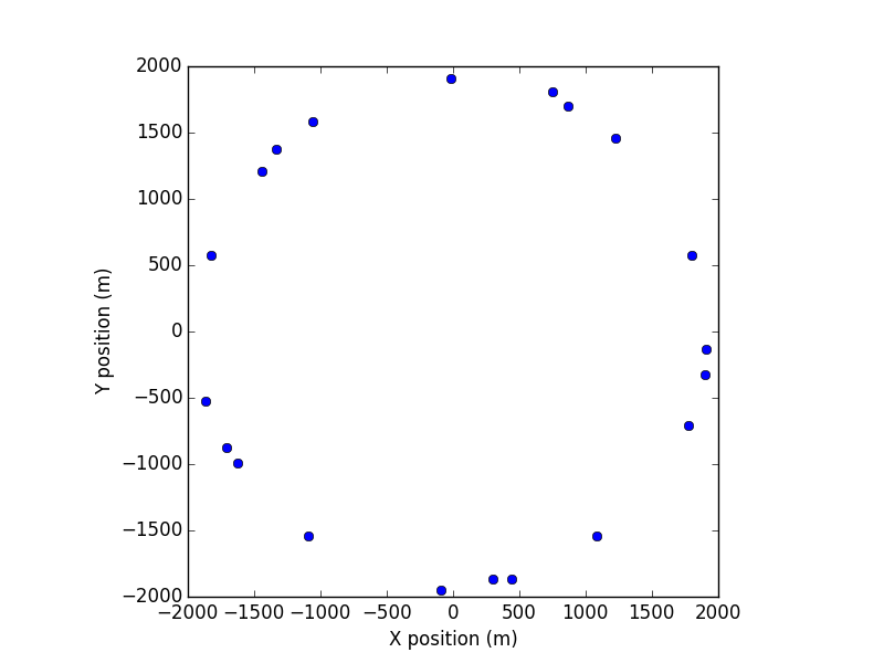
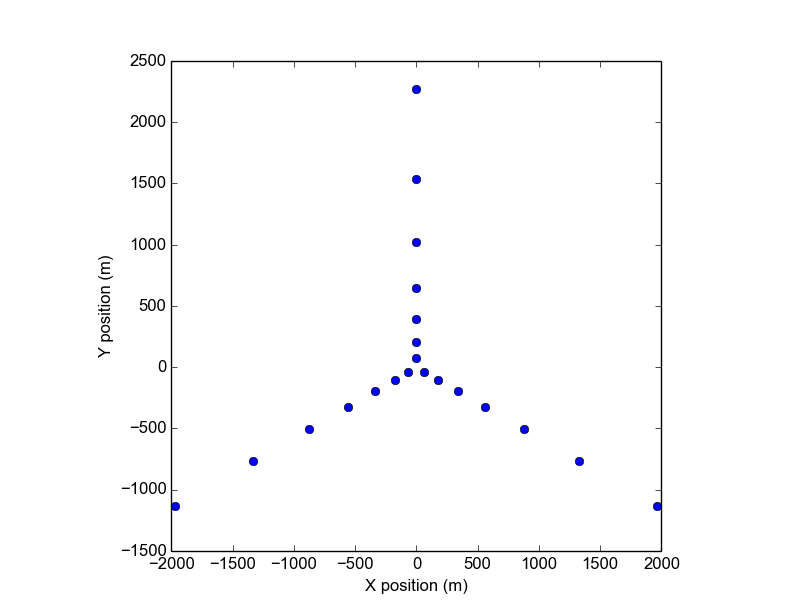
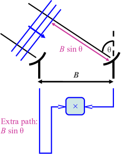
Two reference designs for the array layout of PFI are shown in Fig. 1. To evaluate the worst case propagation distances for each array, we must consider both propagation from the unit telescopes to the beam combining laboratory (assumed to be at the center of the array) and compensation of the geometric delay (Fig. 2) due to projection of the baseline. The maximum geometric delay is for a target on the horizon, aligned with the longest baseline. Of the two possible target directions, the one with the beam combining laboratory nearest to the target is the worst case — the parameters for this case are presented in Table 1.
Scaling the results in Fig. 3 to of 4 km (Table 1) and the longest possible science wavelength of 13 , we find that a beam size of m would be needed to keep the signal loss due to diffraction to 10% or less. If we restrict mid-IR operation to the (3.5 ) and (5 ) astronomical bands, the required beam size is reduced to 1.1 m. Even if we decide to tolerate higher losses (say 20%), and take advantage of the fact that diffraction can provide a helpful spatial filtering effect when atmospheric aberrations are present [5], it is clear that the cost of the vacuum pipes and supports to accommodate such large beams would be prohibitively expensive (both in absolute terms and in comparison with the cost of the unit telescopes).
| Parameter | Pseudo-circular | Y-shaped |
|---|---|---|
| array | array | |
| /m | 163 | 130 |
| /m | 3829 | 3935 |
| Worst-case /m | 1925 | 2272 |
| Worst-case /m | 5761 | 6207 |
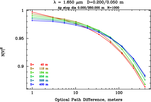
On the other hand, if a heterodyne solution were adopted, the beam size needed for the 1.65 fringe-tracking light, assuming a maximum of 2 km for the nearest and second-nearest-neighbor baselines that will be used to co-phase the array, would be only 0.45 m. This beam size could be accommodated in vacuum pipes with 0.7 m inner diameter, for a feasible cost.
An interesting question is the relative costs of the beam transport hardware for the pseudo-circular and Y-shaped arrays. Both have similar worst-case differential propagation distances, but the beams from the telescopes on each arm travel in parallel to the central laboratory, allowing pipe supports and/or vacuum pipes to be shared between multiple beams. This aspect of the PFI cost model will be examined in more detail later in the design process.
3 Pupil management
There are several options for incorporating pupil management into the beam transport system. The delay lines could consist of either a combination of switchable fixed delays (“long delay lines”) and relatively short ( km) continuously-variable delay lines (as at NPOI and CHARA), or a long variable delay line (as adopted at MROI). For the first option, incorporating pupil management into the switchable fixed delays but not the variable delay lines might be adequate. If long continuously-variable delay lines are used, these would have to incorporate pupil management, for example using variable curvature mirrors as at VLTI [6].
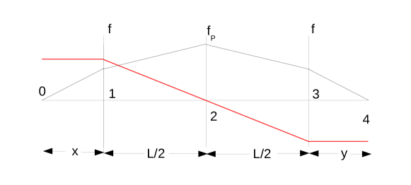
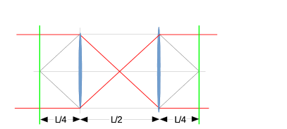
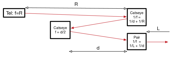
We will illustrate the general principles of pupil relay using simple series of thin lenses, which are straightforward to incorporate into a vacuum pipe. A three-lens design that relays the telescope pupil to a surface in the beam combining laboratory is presented and explained in Fig. 4. For this design, the focal length of the pupil-remapping lens is in the limit , .
There are classes of designs with odd and even numbers of lenses. For the latter class, the overall loss from such a system can be minimised by replacing the vacuum windows at the ends of each pipe with lenses (of sufficient thickness to resist deformation due to the differential air pressure).
Given the initial beam diameter, the desired light loss imposes a minimum clear aperture requirement. In the absence of aberrations, an Airy disk will be formed at the pupil-remapping lenses (e.g. the middle surface in Fig. 8), and the fractional light loss as a function of the aperture size there can be approximated (Fig. 5) as:
| (7) |
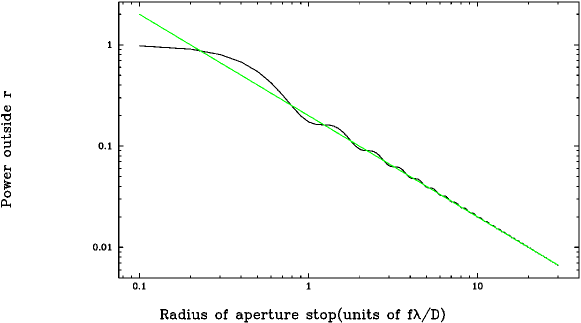
Since the optics will be in a vacuum pipe, we set , hence:
| (8) |
For 10% light loss (), km and , the required feed system diameter is just cm. For and km we require m, a factor of four smaller than that required for propagation without pupil relay.
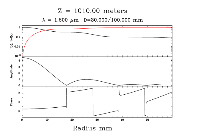
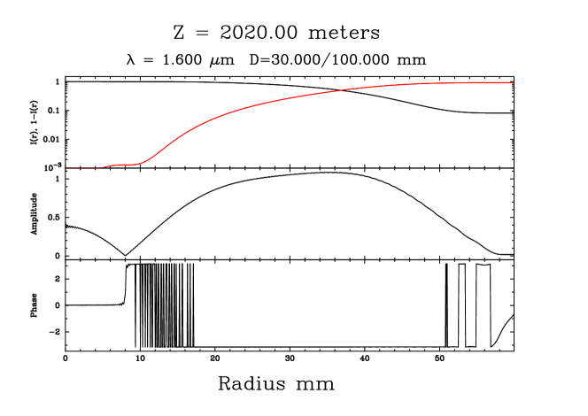
To illustrate the propagation effects, we have evaluated the Fresnel integrals numerically to determine the field at several surfaces of interest, assuming a perfect plane wave ( m) with a 30 mm central obscuration at the entrance pupil (surface 0 in Fig. 4). Figs. 6 and 7 show the beam profiles in the middle of the vacuum system (surface 2) and at the exit pupil (surface 4), for a system with km.
It is important to match the beam profiles to each other, not to the input profile. When light is transported a shorter distance, light loss is decreased and the beam profiles will no longer match causing a reduction in fringe visibility. The profiles can be matched by changing the size of the stops at the pupil-remapping lens.
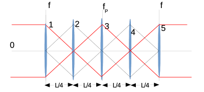
The beam diameter can be reduced by adding more lenses. Fig. 8 shows a design with five lenses, as well as a design with just two lenses. The latter is part of the family of designs using even numbers of lenses.
For all of the designs considered here, the lenses must deliver good image quality across both the near-IR fringe tracking band and the mid-IR science band(s), but need not at the intervening wavelengths. The focal length must also not vary too much with wavelength. We have made an initial exploration of suitable lens designs, and it appears that doublet designs can exceed the required focus tolerance by an order of magnitude.
Reflective equivalents of these designs are of course perfectly valid. In the next section we consider these for use in a system of switchable fixed delays.
4 Delay line concepts
4.1 Variable delay line
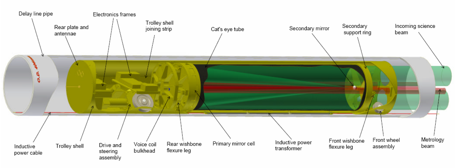
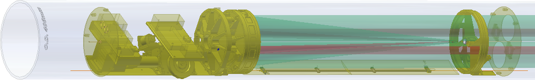
The longest continuously-variable vacuum delay line in existence is at the Magdalena Ridge Observatory Interferometer (MROI). The MROI delay lines [7] have been designed to provide zero to 380 m of continuously-variable delay in vacuum, and have been fully tested up to 200 m of delay. The optical design is a straightforward cat’s-eye without pupil relay. The innovative features are the use of the inner surface of the vacuum pipe to guide and support the movable “trolley” (Fig. 9) that carries the retro-reflecting optics, in conjunction with active control of the return beam shear (to accommodate non-straightness of the vacuum pipe) and the trolley roll angle. To avoid issues with dragging long cables, power is supplied inductively and all communications with the trolley are wireless. The factors limiting straightforward extension of the design to a longer stroke are the coherence length of the laser used in the off-the-shelf metrology system (1 km) and the 1.4 m/s (in delay) slew speed (limited by the inductive power supply and onboard energy storage).
A further option for extending the range of the delay line is to send the beam through the delay line multiple times. This has the advantage of magnifying the slew speed for faster repositioning. Using multiple passes obviously reduces the allowed jitter of the retro-reflecting optics by the reciprocal of the number of passes. MROI has been designed for visible and near-infrared operation, and hence a requirement that the induced optical path jitter not exceed at nm. The design is thus over-specified for the shortest PFI wavelength of 1.65 , and this margin could be used to accommodate several passes while still delivering satisfactory performance.
The MROI delay line design has a clear aperture of 125 mm for the optical beam using vacuum pipe of 15.5 inch (394 mm) inner diameter. The diffraction calculations presented in Fig. 3 indicate that scaling up the dimensions by a factor 2 would be adequate for fringe tracking at 1.65 wavelength on baselines up to 2 km. For science observations in the mid-IR, it would be necessary to use switchable fixed delays in conjunction with short delay lines, and/or incorporate pupil management into the delay line optics. This could be done using a variable curvature mirror as implemented at VLTI [6]. A possible scheme for combining a pupil-managed variable delay line with beam transport from the telescopes to the central beam combining laboratory is shown in Fig. 11 and discussed below.
4.2 Switchable fixed delays
We can use the pupil relay schemes presented in Section 3 as the basis of designs for “long delay lines” that introduce switchable fixed delays in vacuum.
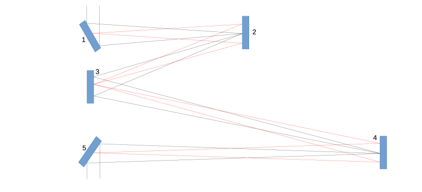
A possible scheme for such a “long delay line” is shown and explained in Fig. 10. This “asymmetric W” design is equivalent to the five-lens design shown in Fig. 8, and requires three variable-curvature surfaces to accommodate a discrete set of positions for the other two surfaces (mirrors 2 and 4), thus allowing appropriate fixed delays to be introduced. Fast switching of the fixed delays would probably be accomplished by making mirrors 2 and 4 “pop-up” mirrors that fold down below the beam when not in use.
A simplification of the asymmetric W can be realised by adopting the two-lens pupil relay scheme from Fig. 8. In this scheme, only the pop-up mirrors have power, and the three other surfaces are just flats, at the cost of larger optics.
To further reduce the amount of real estate and vacuum pipe required, the beam transport and delay line functions can be combined in a single vacuum pipe. Fig. 11 shows a concept design that uses variable curvature mirrors (or multiple curved surfaces of adjustable geometry) to realize this idea.
5 Conclusions
We have evaluated the likely diffraction losses in the PFI beam transport and delay line systems. For direct detection interferometry in the mid-infrared on kilometric baselines, it is clear that these systems must incorporate pupil management to avoid the need for prohibitively large (1–2 m diameter) and hence expensive vacuum pipes. We have presented conceptual designs for switchable fixed delays and continuously-variable delays that incorporate pupil relay. No show-stopping issues were identified.
As we continue to develop the technology roadmap for PFI, we plan to evaluate the possibilities for using optical fibres as an alternative to free-space propagation in vacuum, and to refine the design ideas presented in this paper with a view to selecting the most viable concepts.
References
- [1] J. D. Monnier, S. Kraus, D. Buscher, J.-P. Berger, C. Haniff, M. Ireland, L. Labadie, S. Lacour, H. Le Coroller, R. G. Petrov, J.-U. Pott, S. Ridgway, J. Surdej, T. ten Brummelaar, P. Tuthill, and G. van Belle, “Planet formation imager (PFI): introduction and technical considerations,” Proc. SPIE 9146, p. 914610, 2014.
- [2] S. Kraus, J. D. Monnier, M. J. Ireland, G. Duchene, C. Espaillat, S. Hoenig, A. Juhasz, C. Mordasini, J. Olofsson, C. Paladini, K. Stassun, N. Turner, G. Vasisht, T. J. Harries, M. R. Bate, J.-F. Gonzalez, A. Matter, Z. Zhu, O. Panic, Z. Regaly, A. Morbidelli, F. Meru, S. Wolf, J. Ilee, J.-P. Berger, M. Zhao, Q. Kral, A. Morlok, A. Bonsor, D. Ciardi, S. R. Kane, K. Kratter, G. Laughlin, J. Pepper, S. Raymond, L. Labadie, R. P. Nelson, G. Weigelt, T. ten Brummelaar, A. Pierens, R. Oudmaijer, W. Kley, B. Pope, E. L. N. Jensen, A. Bayo, M. Smith, T. Boyajian, L. H. Quiroga-Nunez, R. Millan-Gabet, A. Chiavassa, A. Gallenne, M. Reynold, W.-J. de Wit, M. Wittkowski, F. Millour, P. Gandhi, C. Ramos Almeida, A. Alonso Herrero, C. Packham, M. Kishimoto, K. R. W. Tristram, J.-U. Pott, J. Surdej, D. Buscher, C. Haniff, S. Lacour, R. Petrov, S. Ridgway, P. Tuthill, G. van Belle, P. Armitage, C. Baruteau, M. Benisty, B. Bitsch, S.-J. Paardekooper, C. Pinte, F. Masset, and G. P. Rosotti, “Planet Formation Imager (PFI): science vision and key requirements,” ArXiv e-prints , Aug. 2016.
- [3] M. J. Ireland and J. D. Monnier, “A dispersed heterodyne design for the Planet Formation Imager,” Proc. SPIE 9146, p. 914612, 2014.
- [4] M. J. Ireland, J. D. Monnier, S. Kraus, A. Isella, S. Minardi, R. Petrov, T. ten Brummelaar, J. Young, G. Vasisht, D. Mozurkewich, S. Rinehart, E. A. Michael, G. van Belle, and J. Woillez, “Status of the Planet Formation Imager (PFI) concept,” ArXiv e-prints , Aug. 2016.
- [5] A. J. Horton, D. F. Buscher, and C. A. Haniff, “Diffraction losses in ground-based optical interferometers,” MNRAS 327, p. 217, 2001.
- [6] M. Ferrari, G. R. Lemaitre, S. P. Mazzanti, P. Lanzoni, F. Derie, P. B. Gitton, and S. Menardi, “VLTI pupil transfer: variable curvature mirrors: I. Final results and performances and interferometric laboratory optical layout,” Proc. SPIE 4006, p. 104, 2000.
- [7] M. Fisher, R. C. Boysen, D. F. Buscher, C. A. Haniff, E. B. Seneta, X. Sun, D. M. A. Wilson, and J. S. Young, “Design of the MROI delay line optical path compensator,” Proc. SPIE 7734, p. 773449, 2010.