Novel morphologies for laterally decorated metaparticles: Molecular dynamics simulation
Abstract
We consider a mesoscale model for nano-sized metaparticles (MPs) composed of a central sphere decorated by polymer chains with laterally attached spherocylinder. The latter mimics the mesogenic (e.g., cyanobiphenyl) group. Molecular dynamics simulations of MPs reveal the existence of two novel morphologies: (hexagonal columnar arrangement of MPs with strong uniaxial order of mesogens collinear to the columns axis) and [the same arrangement of MPs but with weak or no liquid crystalline (LC) order]. Collinearity of the LC director and the columnar axis in morphology indicates its potentially different opto-mechanical response to an external perturbation as compared to the columnar phase for the terminally attached mesogens. Preliminary analysis of the structures of both phases is performed by studying the order parameters and by visualisation of the MPs arrangements. Different mechanisms for the mesogens reorientation are pointed out for the cases of their terminal and lateral attachment.
Key words: nanoparticles, liquid crystals, self-assembly, molecular dynamics
PACS: 02.70.Ns, 61.30.Vx, 61.30.Cz, 61.30.Gd
Abstract
Розглянуто мезоскопiчну модель нанорозмiрних метачастинок (МЧ), якi складається iз центральної сфери, декорованої полiмерними ланцюжками iз бiчним приєднанням сфероцилiндрiв. Останнi описують мезогеннi (напр. цианобiфенiльнi) групи. Виконанi симуляцiї МЧ за допомогою молекулярної динамiки вказують на iснування двох нових морфологiй: (iз гексагональним стовпцевим впакуванням МЧ та сильним одновiсним впорядкуванням рiдкокристалiчних груп колiнеарно до осi стовпцiв) та (iз тим же впорядкування МЧ але слабким або вiдсутнiм рiдкокристалiчним впорядкуванням). Колiнеарнiсть директора та осi симетрiї стовпцевої фази у морфологiї вказує на її потенцiйно iншу оптико-механiчну реакцiю на зовнiшнє збурення порiвняно iз стовпцевою фазою для моделi iз кiнцевим приєднанням рiдкокристалiчних груп. Попереднiй аналiз структур обох фаз виконано шляхом дослiдження параметрiв порядку та вiзуалiзацiєю розташування МЧ. Вказано на роль рiзних механiзмiв реорiєнтацiї мезогенiв залежно вiд способу їх приєднання.
Ключовi слова: наночастинки, рiдкi кристали, самовпорядкування, молекулярна динамiка
1 Motivation
Colloid particles, polymers and LC molecules represent main building blocks of soft matter physics [1]. When two or more of such blocks are combined into a MP, the latter forms a meta-material that exhibits a range of new morphologies and new effects that are not observed for any of its pure constituents. Examples to mention are: LC elastomers, LC dendrimers, decorated nanoparticles and others [2, 3, 4, 5, 6, 7], all of these having already found a number of applications in thermo- and photo-controlled elasticity, plasmonic resonance, photonics and medicine. Most applications rely on the symmetry of the equilibrium morphology, in which each constituent is ‘‘responsible’’ for particular property of a meta-material. For instance, its elasticity is usually controlled by a polymer subsystem, optical properties are governed by both the behaviour of mesogens and the arrangement of gold nanoparticles (if any). Therefore, the type of mutual arrangement of the constituent parts is crucial regarding the new potential applications of each particular meta-material.
Let us concentrate on the MPs built out of a spherical core decorated by polymer chains (spacers) each ending by a mesogen. The core mimics either a solid nanoparticle (e.g., gold nanoparticle [6, 7]) or averaged in time shape of a dendritic scaffold [4, 5]. It was found experimentally that the most important aspects of decoration are as follows: the surface density of mesogens on the outer shell of MP, the length of a spacer, and the exact way mesogens are attached chemically to the spacer [4, 5, 6, 7, 8, 9, 10, 11]. In particular, both terminal and lateral attachment can be realised chemically [4, 5, 8, 9, 10, 11] [depicted schematically in figure 1 (a) and (b)] and the difference between the morphologies observed in these two cases are in the focus of this study.
The case of a terminal attachment of mesogens [figure 1 (a)] has been studied more widely out of the two [4, 5, 6, 7]. In particular, at low grafting density of chains such MPs adopt a rod-like conformation
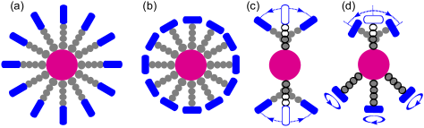
and self-assembly into lamellar smectic A morphology [see, figure 2 (a)]. With an increase of a grafting density, the disc-like conformation for MPs is favoured over the rod-like one, and the MPs self-assemble into columns which arrange themselves hexagonally [see, figure 2 (b)]. Both structures possess uniaxial symmetry denoted via the symmetry axis . For the morphology (a) it is defined as a normal vector to the layers (and it also coincides with the preferential direction for MPs rods), whereas for its (b) counterpart is defined along the columns of MPs. Despite this common feature, the different type of MPs arrangement in these morphologies will affect their elastic properties and their behaviour in plasmonic resonance applications (if the cores represent gold nanoparticles). Their behaviour will differ even more in the applications related to the optical activity and orientational order of mesogens. Indeed, morphology (a) is characterised by an uniaxial preferential orientation of mesogens defined via nematic director , whereas for the case of morphology (b) the global director does not exist. The distribution of mesogens orientations in this case is flat radial centered around the axes of each column [as indicated in figure 2 (b)]. One can clearly see some analogy with the case of LC elastomers, where the role of a symmetry axis can be attributed to the preferential orientation of the polymer backbones [2, 3]. It is well known that their opto-mechanical applications depend heavily on the mutual arrangement of and axes, the main- and side-chain architectures being an example [2, 3, 12, 13, 14, 15, 16].
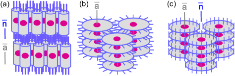
Therefore, a question arises whether some other morphologies can be obtained for the MPs with lateral attachment of mesogens [figure 1 (b)] which are characterised by different mutual arrangement of the and axes, leading potentially to new optical and opto-mechanical behaviour. Based on this MP geometry, one would expect the formation of hexagonal columnar morphology depicted in figure 2 (c). It should be quite similar to its counterpart (b) (shown in the same figure) in terms of its mechanical properties and the arrangement of cores, but, crucially, is characterised by uniaxial orientational order with the nematic director shown as therein. Moreover, are there any other morphologies possible? We try to provide the answer in the following section by means of coarse-grained molecular dynamics simulations.
2 Results and discussion
The model for a MP with laterally attached mesogens is based on its counterpart with terminal attachment described in detail in references [17, 18]. The central sphere represents a core (be it a gold nanoparticle or a dendritic core) decorated by grafting chains to it. We use the annealing-like grafting, when the first bead of each chain slides freely on the surface of a central sphere. The effective diameters of soft beads are based on the coarse-graining of the atomistic model for the generation 3 LC dendrimer performed in reference [19]. These are: for a central sphere, for the first bead and for the remaining beads of the spacer which connects mesogens to the central sphere.
The spheres interact via soft repulsive potentials of a quadratic form [17, 18]. The mesogens are modelled as soft spherocylinders of the breadth and of the length-to-breadth ratio . These dimensions are also used for the visualization purpose. The MP is kept together by means of harmonic spring potentials, with the same parameters used for the model with terminal attachment [17, 18]. As far as each monomer is assumed to represent three hydrocarbons [19] and their dimension is less than the Kuhn segment length, we introduce the pseudo-valent angles which account for the effective spacer stiffness [17, 18].
Orthogonal lateral attachment of the mesogen to the spacer [figure 1 (b)] is maintained by employing two potentials. First one is the usual harmonic bond potential between the center or the last monomer of the spacer and the center of the spherocylinder, the bond length is . The second potential is also of a harmonic type with respect to the angle between the latter bond and the long axis of a mesogen [20]. The equlibrium value for this angle is set equal to . The force constant for the latter potential is set equal to its counterpart for the pseudo-valent angle potential mentioned above (the absolute value can be found in references [17, 18]).
In this study, we consider the MPs with grafted chains only. The initial configuration is build out of such MPs arranged randomly in a simulation box. The initial orientation of grafted chains is radial, with respect to the central sphere. Typical box dimensions are of the order of and the periodic boundary conditions are used in the simulations. First, a short run is performed of molecular dynamics steps with a small time step of to eliminate initial interparticle overlaps. Following the scheme employed in references [17, 18], we performed field-assisted self-assembly simulations first. These are done at a fixed temperature by imposing an external orienting field. The latter is introduced via additional energy term , which contains a contribution from each th mesogen. Here, is the angle between the field direction and the orientation of th mesogen, is the magnitude of the field. Throughout this study we assume that the field is always directed along the axis of the Cartesian frame. Its magnitude sets a time-scale for the mesogens reorientation and we found empirically the values in the range of to be optimal for our state points. The simulations are performed in anisotropic isobaric ensemble, where the temperature and each of the three diagonal components of the stress tensor are maintained constant by means of the thermostat and three separate barostats [13, 14, 15, 16]. This makes possible the auto-adjustment of the simulation box shape which at the end becomes commensurate with the pitch of the emerging ordered phase. One should remark that the potential interactions used in this model are predominantly soft repulsive (save for the mesogen-mesogen potential introduced by Lintuvuori and Wilson [21]). Therefore, to maintain the density required for the ordered phases, the system needs to be stabilized by the pressures of [17, 18].
The field-assisted self-assembly simulations are performed for the range of pressures , the duration of each run is molecular dynamics steps with a time step of . For all values of the pressure within this interval, the system indeed self-assembles into the uniaxial hexagonal columnar morphology depicted schematically in figure 2 (c) and thereafter referred to in this study as . Dependence of this morphology on the pressure is reflected only in the density of stacking of MPs into columns, as well as in the total density of the system. We will provide simulation snapshots for this morphology below. The next stage is to test the stability of this structure and the changes it undergoes in a wide range of temperatures when the aiding field is removed (). To provide a quantitative analysis of these changes, let us introduce a set of the order parameters.
The level of orientational order of mesogens is described by the nematic order parameter defined as:
| (1) |
where is the angle between the orientation of th mesogen and nematic director axis , and is the second Legendre polynomial. The averaging is performed over all mesogens in a system and over the time trajectory denoted as . The initial director was set along the axis in the course of a field-assisted run. And, similarly to the case of MPs with terminally attached mesogens [17, 18], we found a negligible drift of the director away from this axis for all temperatures where the orientation order exists whatsoever. Therefore, in this study we assume to be the angle between the orientation of th mesogen and the axis.
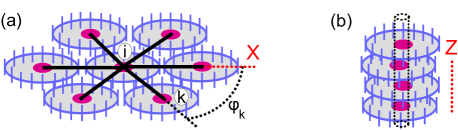
The amount of the ‘‘hexagonality’’ in the arrangement of MPs in the plane can be characterized by the hexagonal order parameter , introduced as follows. Let us consider th MP and identify its first coordination circle in the plane. To this end, we evaluate the bond vectors between its center to the centers of each of its neighbours indexed via . The bond lengths between th and th MPs projected onto the plane are: . The neighbour is assumed to belong to the first coordination circle of th MP if the following conditions fulfill: and . For our model, we choose the following set of parameters: , and but the choice, obviously, depends on the geometry of the model MP. After the first coordination circle that contains MPs are identified, the arbitrary axis in the plane is chosen (e.g., the axis) and the angles are evaluated for each th MPs belonging to this circle [see, figure 3 (a)]. Then, both the local hexagonal order for th MP and its global counterpart can be defined via equation (2) as:
| (2) |
Here, . The same equation also contains a definition for the other order parameter, , which accounts for the ‘‘columnarity’’ of the phase, i.e., the amount of stacking of the MPs discs along the axis. It can be related to the average columns height which is identified by considering th MP and drawing through its center an imaginary cylinder of radius that extends along the axis [see, figure 3 (b)]. Then, one takes into account the number of MPs so that their centers are found inside this cylinder (periodic boundary conditions are not taken into account). Normalisation factor is introduced for convenience, to bring the range of values to the same interval as the other two order parameters, and . We used the following values: and . These notations explain the expressions for the columnar order parameter in equation (2).

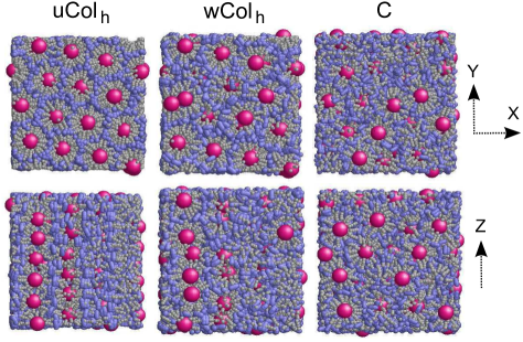
Let us concentrate on the behaviour of the order parameters , and when the uniaxial hexagonal columnar phase , obtained by the field-aided self-assembly, is equilibrated at various temperatures. The plots demonstrating the changes are provided in figure 4. At relatively low temperatures, K, the values of all three order parameters are essentially non-zero and one obtains the uniaxial hexagonal columnar phase first depicted schematically in figure 2 (c). It is characterized by both uniaxial nematic order along the axis and regular columns of disc-shaped MPs aligned along the same axis and arranged hexagonally in the plane (see snapshots in the left-hand column of figure 5). With an increase of the temperature, all order parameters gradually decay to their minimum values. First of all, let us note that decays very fast (practically linearly), in contrast to the case of terminally attached mesogens [17, 18], where the shape of the curve for had a semi-dome-like shape indicative of a power law form. More importantly, in the case considered there, the decrease of and of the asphericity of the molecules was synchronous: both turned to zero at about K. For the laterally attached mesogens considered here, we observe an essential delay in the decrease of two other order parameters, and , as compared to . As one can see in figure 4, there is a narrow temperature range around K, where the value of dropped to about (typical of the isotropic phase), but and are still almost the same as in the morphology at K. One may refer to this morphology as a weak hexagonal columnar () and the important feature of it is that while it lost the orientation order of mesogens, its hexagonal columnar structure is essentially preserved (see snapshots in the middle column of figure 5). One should note that the transition from to is gradual and the boundary between both shown in figure 4 is rather for illustrative purpose. With further heating of the system, the values for the order parameters and drop to their minima at approximately K. The phase observed at the temperatures higher than that is a cubic phase (C), where the MPs adopt the form close to spherical due to an increased conformational entropy. Its structure is shown in the right-hand column of figure 5 and is the same as for the case of terminally attached mesogens [17, 18].
The faster decay of with an increase of the temperature and, as a result, the evidence of a new morphology can be explained by the following considerations. Let us go back to figure 1 (a) and (b) and consider the difference in the allowed mechanisms for the mesogens reorientation in both cases. These are shown schematically in the same figure, frames (c) and (d) for the cases of terminal and lateral attachment, respectively. For the case of a terminal attachment, if we assume that the grafting point does not drift much, the only way for a mesogen to change its orientation is to bend the spacer [see, figure 1 (c)]. There will be the energy penalty associated with this change due to the pseudo-angle potential term which is introduced to model the stiffness of the alkyl chain at a meso-scale level. This mechanism of bending the chain also exists for the case of laterally attached mesogens [figure 1 (d), top chain with respect to the central sphere]. However, there also exists another mechanism of rotating a mesogen around the bond which connects it to the end monomer of a spacer [figure 1 (d), bottom chains with respect to the central sphere]. This rotation costs no energy, as far as both bond length between a mesogen and the last monomer and the angle between the orientation of a mesogen and the same bond stay unchanged. As a result, the rotational motion of mesogens in the mesogen-rich regions is more decoupled from the elastic energy of the spacers in the case of laterally attached mesogens compared to the case of their terminal attachment. This is, most likely, the main reason for a faster decrease of the nematic order with the raise of the temperature in the former case. We should note that the conformational changes in real systems involve more factors to be considered, as compared to the current coarse-grained modelling. In particular, both reorientation mechanisms depicted in figure 1 (d) are likely to be realized via soft interactions such as torsional angles changes. Therefore, a more detailed analysis is needed to compare the energy penalty for both mechanisms of the mesogens reorientation discussed here.
To conclude, we have shown the possibility of the formation of two novel morphologies, and for the MPs with lateral attachment of mesogens. The former is uniaxial in both the symmetry of MPs packing and in the arrangement of its mesogens. The latter is characterized by the same symmetry of MPs packing, while its LC subsystem is in the isotropic phase. Both morphologies differ in their LC properties from their counterpart for the MPs with terminal attachment of mesogens and are candidates for specific opto-mechanical applications.
References
-
[1]
Kleman M., Lavrentovich O.D., Soft Matter Physics: An Introduction, Springer, New York, 2003;
doi:10.1007/b97416. - [2] Warner M., Terentjev E.M., Liquid Crystal Elastomers, Oxford University Press, Oxford, 2007.
- [3] Behl M., Lendlein A., Mater. Today, 2007, 10, 20; doi:10.1016/S1369-7021(07)70047-0.
- [4] Saez I.M., Goodby J.W., J. Mater. Chem., 2005, 15, 26; doi:10.1039/b413416h.
- [5] Saez I.M., Goodby J.W., In: Liquid Crystalline Functional Assemblies and Their Supramolecular Structures, Structure and Bonding Series Vol. 128, Kato T. (Ed.), Springer, Berlin, 2008, 1–62; doi:10.1007/430_2007_077.
- [6] Draper M., Saez I.M., Cowling S.J., Gai P., Heinrich B., Donnio B., Guillon D., Goodby J.W., Adv. Funct. Mater., 2011, 21, 1260; doi:10.1002/adfm.201001606.
- [7] Bisoyi H.K., Kumar S., Chem. Soc. Rev., 2011, 40, 306; doi:10.1039/b901793n.
- [8] Saez I.M., Goodby J.W., J. Mater. Chem., 2003, 13, 2727; doi:10.1039/b303654e.
-
[9]
Martín-Rapún R., Marcos M., Omenat A., Serrano J.-L., Luckhurst G.R., Mainal A., Chem. Mater., 2004, 16, 4969;
doi:10.1021/cm049191l. - [10] Pastor L., Barberá J., McKenna M., Marcos M., Martín-Rapún R., Serrano J.-L., Luckhurst G.R., Mainal A., Macromolecules, 2004, 37, 9386; doi:10.1021/ma048450p.
- [11] Wilson M.R., Stimson L.M., Ilnytskyi J.M., Liq. Cryst., 2006, 33, 1167; doi:10.1080/02678290600973113.
- [12] Ikeda T., Mamiya J., Yu Y., Angew. Chem. Int. Ed., 2007, 46, 506; doi:10.1002/anie.200602372.
- [13] Ilnytskyi J.M., Neher D., J. Chem. Phys., 2007, 126, 174905; doi:10.1063/1.2712438.
- [14] Ilnytskyi J.M., Neher D., Saphiannikova M., Condens. Matter Phys., 2006, 9, 87; doi:10.5488/CMP.9.1.87.
- [15] Ilnytskyi J.M., Neher D., Saphiannikova M., J. Chem. Phys., 2011, 135, 044901; doi:10.1063/1.3614499.
- [16] Ilnytskyi J.M., Saphiannikova M., Neher D., Allen M.P., Soft Matter, 2012, 8, 11123; doi:10.1039/c2sm26499d.
- [17] Ilnytskyi J.M., Lintuvuori J., Wilson M.R., Condens. Matter Phys., 2010, 13, 33001; doi:10.5488/CMP.13.33001.
- [18] Ilnytskyi J.M., Condens. Matter Phys., 2013, 16, 43004; doi:10.5488/CMP.16.43004.
- [19] Hughes Z.E., Wilson M.R., Stimson L.M., Soft Matter, 2005, 1, 436; doi:10.1039/b511082c.
- [20] Wilson M.R., J. Chem. Phys., 1997, 107, 8654; doi:10.1063/1.475017.
- [21] Lintuvuori J.S., Wilson M.R., J. Chem. Phys., 2008, 128, 044906; doi:10.1063/1.2825292.
Ukrainian \adddialect\l@ukrainian0 \l@ukrainian
Новi морфологiї метачастинок декорованих шляхом бiчного приєднання рiдкокристалiчних груп: компютерна симуляцiя
А.Ю. Слюсарчук, Я.М. Iльницький
Нацiональний унiверситет ‘‘Львiвська полiтехнiка’’, вул. С. Бандери, 12, 79013 Львiв, Україна
Iнститут фiзики конденсованих систем НАН України, вул. I. Свєнцiцького, 1, 79011 Львiв, Україна