Use of Silicon Photomultipliers in ZnS:6LiF scintillation neutron detectors: signal extraction in presence of high dark count rates
A. Stoykov, J.-B. Mosset, U. Greuter, M. Hildebrandt, N. Schlumpf
Paul Scherrer Institut, CH-5232 Villigen PSI, Switzerland
We report on the possibility of using Silicon Photomultipliers (SiPMs) to detect the scintillation light from neutron conversion in ZnS:6LiF scintillators. The light is collected by wavelength-shifting fibers embedded into the scintillator. The difficulty of extracting neutron signals in the presence of high dark count rates of the SiPMs is addressed by applying a dedicated processing algorithm to analyze the temporal distribution of the SiPM pulses. With a single-channel prototype detection unit we demonstrate a very good neutron signal extraction at SiPM dark count rates of about 1 MHz.
Keywords: SiPM, MPPC, neutron detector, ZnS:LiF, WLS fiber
1 Introduction
The current approaches [1, 2, 3, 4] for large-area multi-channel detectors for thermal neutrons which are based on the scintillation process in ZnS:6LiF (ZnS:10B203) screens use photomultiplier tubes (PMTs) to detect the scintillation light collected through clear or wavelength-shifting (WLS) fibers. Equipping each detection channel with its own single-anode PMT is not realistic due to cost and detector volume considerations. Light-sharing schemes are applied to reduce the total number of PMTs to be built in. Using multi-anode PMTs (MaPMTs) in combination with WLS fibers individual channel readout becomes feasible. Silicon Photomultipliers (SiPMs) [5], being compact and significantly less expensive than MaPMTs, could turn out to be advantageous if being used in readout schemes utilizing WLS fibers. But, in contrast to MaPMTs, the intrinsic dark count rates of SiPMs operated at room temperature are orders of magnitude higher. Accordingly, a direct replacement of MaPMTs by SiPMs in the neutron detection systems would require substantial reduction of the SiPM dark count rate which can only be achieved through a deep cooling of the photosensor [5, 6]. Although technically this approach is clearly feasible, the necessity to cool the SiPMs would add to the complexity and to the cost of the detection system which may outweigh all the advantages expected from their usage.
In this work we aim at developing a SiPM based ZnS:6LiF neutron detector operated at room temperature. The long emission time of the ZnS scintillator, where only 25 % (60 %) of the photons are emitted within the first 1 s (10 s) of a neutron scintillation event [7], and the deficient light collection due to the poor transparency of the scintillator make it difficult to combine a high trigger efficiency for the neutron signals with a reasonable suppression of the SiPM dark counts. We solve this problem by optimizing the light collection from the scintillator and by developing a signal processing system capable to reliably identify neutron signals against the high background of the SiPM dark counts.
2 Requirements on the prototype detector
The main performance characteristics of ZnS:6LiF (ZnS:10B203) neutron detectors are neutron detection efficiency, which is a product of the neutron absorption probability in the scintillator and the trigger efficiency of the signal processing system, background (quiet) count rate, gamma-sensitivity, pulse-pair resolution (dead time), and multi-count ratio. Typical values for these parameters can be found in [1, 2, 3, 4]. It is interesting to note the following: the trigger efficiency has negative correlation with all other parameters, i.e. by lowering the efficiency the detector performance in all other aspects is improved. With a low dark-count rate photosensor (PMT) it is in principle possible to have at the same time a trigger efficiency close to 100 % and a low background count rate. In practice, however, it would require to operate the detector with a rather long dead time to ensure that the system does not trigger on the afterglow photons and the requirement on the multi-count ratio is also fulfilled. Having the dead time in the order of 5 s (typical value to ensure reasonable rate capabilities of the detector) together with the requirement on the multicount ratio (typically below 1 %) essentially leads to trigger efficiency values well below 100 % (even down to % as in [3]). With the low dark count rate photosensor (PMT) one faces, in principle, the same problem, as with a high dark count rate photosensor (SiPM). Namely in both cases one has to suppress unwanted counts. Only in the case of PMTs these counts correspond to afterglow photons and in case of SiPMs to both afterglow photons and dark counts.
With the single-channel prototype detector presented in this work we aim to satisfy the requirements of the POLDI time-of-flight diffractometer [8] on the neutron detection efficiency ( % at the wavelength of 1.2 Å) and on the background count rate ( Hz). The required neutron detection efficiency is to be achieved as a product of % neutron absorption probability in the scintillator and the trigger efficiency of the signal processing system of %. Evaluation of other detector characteristics as well as optimization studies (which have to be performed taking into account all the detector parameters) will be a subject of further investigations.
The above specified detector parameters have to be satisfied at SiPM dark count rates up to MHz. This requirement comes from the following consideration. Hamamatsu SiPMs of type MPPC S12571-025C or MPPC S12571-050C with 1 x 1 mm2 active area are planned to be used. At room temperature the dark count rate of these devices is kHz [9]. During operation of the detection system we expect, taking into account the radiation conditions at POLDI, an increase of the SiPM dark count rate by about 90 kHz per year conditioned by an increase of the concentration of radiation defects in silicon [10]. Accordingly, requiring that the detector parameters have to be guaranteed up to MHz dark count rate of the SiPM is equivalent to the requirement that they are to be guaranteed for about 10 years of detector operation.
3 Test scintillator structure
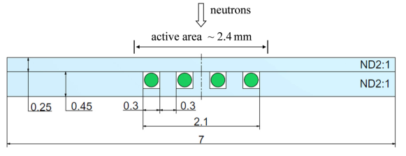
Figure 1 shows a cross-section of the single-channel scintillator unit (see also [8]) used in the current tests. The unit consists of two layers (0.25 mm and 0.45 mm thick) of ZnS:6LiF scintillation material (ND2:1 neutron detection screens from Applied Scintillation Technologies [11]) glued together using EJ-500 optical epoxy from Eljen [12]. Four WLS fibers of type Y11(200)M from Kuraray [13] are glued (with the same epoxy) into the grooves made in the thicker layer. At one side of the unit the fibers are cut along its edge and polished. An aluminized Mylar foil serving as specular reflector is glued on these polished fiber ends to increase the light yield at the other fiber ends connected to a SiPM. The effective channel width is defined by the area covered by the fibers and is about 2.4 mm. The additional space to the total width of 7 mm is used for handling purposes only. The length of the structure is 50 mm.
In a later multi-channel detector this 2.4 mm wide groove/WLS fiber pattern without the additional handling space will be repeated to cover the needed neutron sensitive area. By stacking 4 scintillator units of this type, one behind each other, the required neutron absorption probability of % for 1.2 Å neutrons will be achieved. In this estimate we use the value of cm-3 for the concentration of 6Li atoms in the ND2:1 screens which is deduced from our own absorption measurements.
4 Photon detection and signal processing
In the present measurements a 3 x 3 mm2 MPPC S12572-050C from Hamamatsu [9] was used as the photon detector. The SiPM was operated with a bias voltage of 67.8 V (overvoltage 2.3 V) at 23.5 oC. The dark count rate at these operating conditions is MHz.
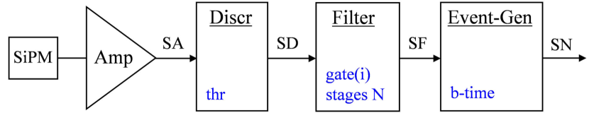
The implemented signal processing algorithm is not following the way of integrating the photosensors analog signals with subsequent pulse-duration analysis like, for example, in [7]. In the case of SiPMs, where fluctuations of one-electron signals can be rather large as a result of the optical cross-talk, such integration would add to the fluctuations of the resulting signal and thus deteriorate the dark-count rejection capability of the detector. The signal processing system proposed here is based on a fast single photon detection followed by a time domain filtering. The basic elements of the processing chain for the SiPM signals are presented in Figure 2. It includes a high band-width amplifier, a leading-edge discriminator, a multistage filter, and an event generator unit.
The SiPM signal is amplified and shaped by a wide band-width gain stage; each SiPM pulse corresponds to one primary charge carrier triggering an avalanche breakdown in one (or more than one by optical cross-talk) of the SiPM cells. This signal is fed into a fast leading edge discrimination stage accepting all SiPM pulses generated either by scintillation photons or thermally. Figure 3 shows a scope screenshot (persistence mode) of the amplified SiPM pulses (SA) and the generated discriminator signals (SD). This kind of “digitalization” eliminates the effect of the SiPM cross-talk on the performance of the detector and allows for a further signal processing scheme being independent of the SiPM type.
The SD pulse sequence is processed by a “single-pulse elimination” filter implementation (see Figure 4). The delay lines are chosen in order to prevent the initiating SD respectively SF(i) pulses to pass the coincidence-AND gates. To pass this type of filtering stage, a pulse at its input has therefore to show up with a preceding pulse (being part of a pulse group) within the time interval defined by the width of the internal gate (retriggerable mono-flop type) signal, i.e. single pulses and always the first pulse from a group of consecutive pulses are removed from the SD respectively SF(i) pulse sequence. At the ED(i) outputs the number of remaining events (pulse groups built by the retriggerable mono-flops) can be counted. This counting is only done to analyse the filter performance, e.g. to determine the remaining dark count rate dependence on the number of stages, and is not necessarily to be implemented.
This kind of filter is scalable, i.e. its basic unit stage can be supplemented by any number of the same basic unit. The adjustable parameters of such a filter type are the gate width (each stage is individually configurable) and the number of consecutive filter stages. When building up multiple filter stages in series the following choice of the time constants is of practical interest: .
Choosing the time constants for all the stages equal means that the initial timing criterium defined by the parameter gate(1) has to be fulfilled N times. To pass N stages of such a multistage filter the SD pulses at its input should appear in groups of at least pulses with temporal distances between them not exceeding the value of gate(1). The first N pulses of such a group will be removed by the filter and the rest will pass through. The residual dark-count rate after stage N of the filter can be approximated with the following empirical dependence:
| (1) |
where is the dark count rate at the filter input and is the coincidence time at the first filter stage calculated as the sum of gate(1) and the width of the SD pulse ( ns, see Figure 3).
Selecting the time constants greater than gate(1) allows for gaps up to this new longer time constant within the pulse sequence decimated by the first stage. This choice affects only slightly the dark-count rejection capabilities of the filter, minor increase of the parameter in (1), but it is definitely more favorable for transmitting the scintillation signals as they are characterized by an increased SD pulse density over a rather long (microseconds) period of time.
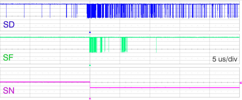
Figure 5 shows an example of measured SD and SF pulse sequences from the detection of one neutron scintillation event. The first pulse of the SF signal (a subsequence of SD pulses passing the filter) is triggering the event generator (a retriggerable mono-flop with adjustable pulse width) generating an event signal SN. The width of the SN signal is set to prevent multiple triggers from the same scintillation event (late after-glow photon elimination). Note, that the appearance of a second neutron event within the duration of the first one will lead to an increase of the density (and not the amplitude) of the analog signals SA after the amplifier and to a corresponding increase of the density of the SD pulses after the discriminator. These two events will be detected as one event if the time interval between them is smaller compared to the blocking time of the event generator (depending on the strength of the second event the blocking time might be prolonged) or as two events otherwise.
5 Measurements
The trigger efficiency of the detector was measured using a calibrated alpha source. To find out how representative the measurements with the alpha source are, the distribution of the number of detected photons measured with alpha particles was compared with that measured with neutrons from a weak non-calibrated neutron source.
The 241Am alpha source is a tablet with a diameter of mm covered with a 0.2 mm thick aluminium plate having a 16 x 1.6 mm slit serving as a collimator. The source was positioned below the scintillator structure (see Figure 1). The energy of the alpha-particles is MeV, their penetration depth into the scintillator is m. Consequently, the minimum path for the scintillation light from the point of emission to absorption in a WLS fiber is m. For absolute efficiency measurements the source was calibrated in the following way: a plastic scintillator was mounted on the photocathode of a photomultiplier tube and the intensity of alpha-particles was measured to be 1/s. The detection threshold was set low enough to ensure that all alpha-events were detected.
Thermalized neutrons were obtained from a 241AmBe source (activity neutrons/s) enclosed in a polyethylene moderator. The rate of thermal neutrons detected with our test detector unit was in the order of 1 count per second. As the neutron interactions are distributed more uniformly within the scintillator volume compared to the alpha-particle interactions close to the surface of the scintillator, the light collection conditions are expected to be more favorable in case of neutrons.
The performance of the detector is fully determined by the following parameters of the signal processing system: discrimination threshold on the SiPM analog signals, the number of filtering stages N, the gate widths of the first gate(1) and the following filter stages, and the duration of the output pulse of the event generator (blocking time).
The discrimination threshold can be set at any value below the minimum amplitude of the SiPM one-cell signals (see Figure 3): as long as all these signals are accepted the threshold value does not influence the parameters of the detector.
The blocking time was fixed at a rather large value of 100 s to ensure that in all range of variation of the filter parameters the multicount ratio is below 1 %.
The filter gate widths were fixed at the value of 200 ns to ensure the fulfillment of the condition in the whole range of the foreseen variation of the parameter gate(1).
The range of variation of the parameters gate(1) and N was established from the following consideration. An efficient suppression of the SiPM dark counts with a reasonable (about 10) number of filter stages requires, see formula (1), the parameter to be in the order of 0.1 or below. At the dark count rate of 1 MHz this corresponds to ns. Suppression of the dark count rate to at least Hz, i.e. by 8 orders of magnitude, would require with gate(1) = 100 ns about filter stages. Accordingly, the parameters gate(1) and N were varied in the present measurements as: ns and .
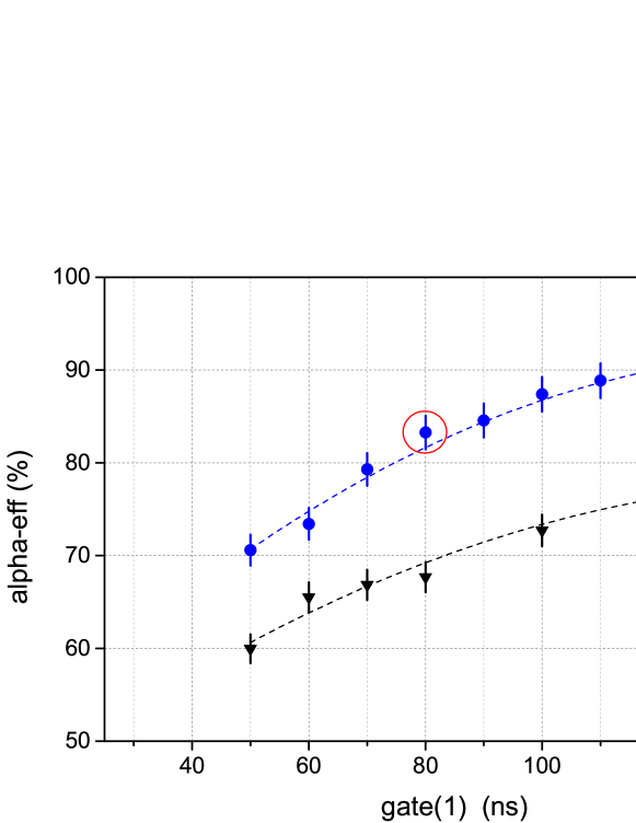
Figure 6 shows the measured trigger efficiency for alpha-particles as a function of the parameter gate(1) at N = 8 and 10. The required efficiency of % is achieved at N = 8 and ns.
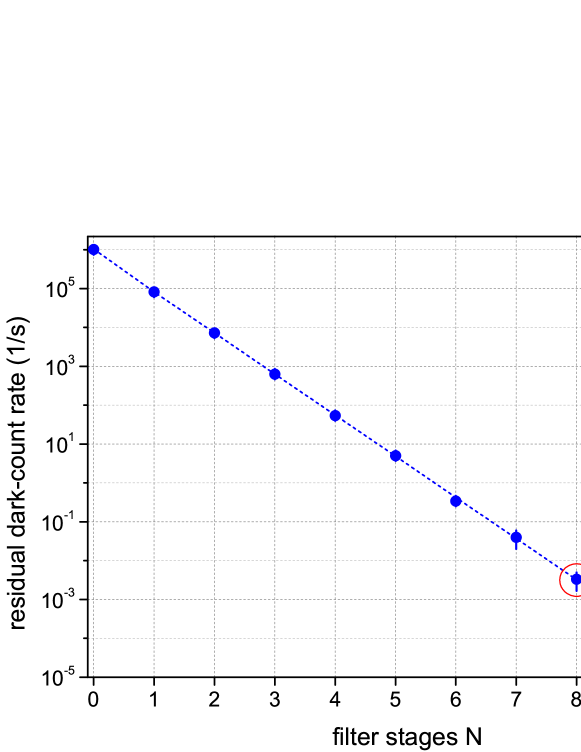
Figure 7 shows the rate of residual dark counts at the filter output as a function of the total number N of filtering stages at gate(1) = 80 ns. Each stage is suppressing the dark-count rate by a factor of about 10, so that at (where we get the trigger efficiency of %) the residual output dark-count rate (background count rate of the detector) reaches the required value of about Hz.
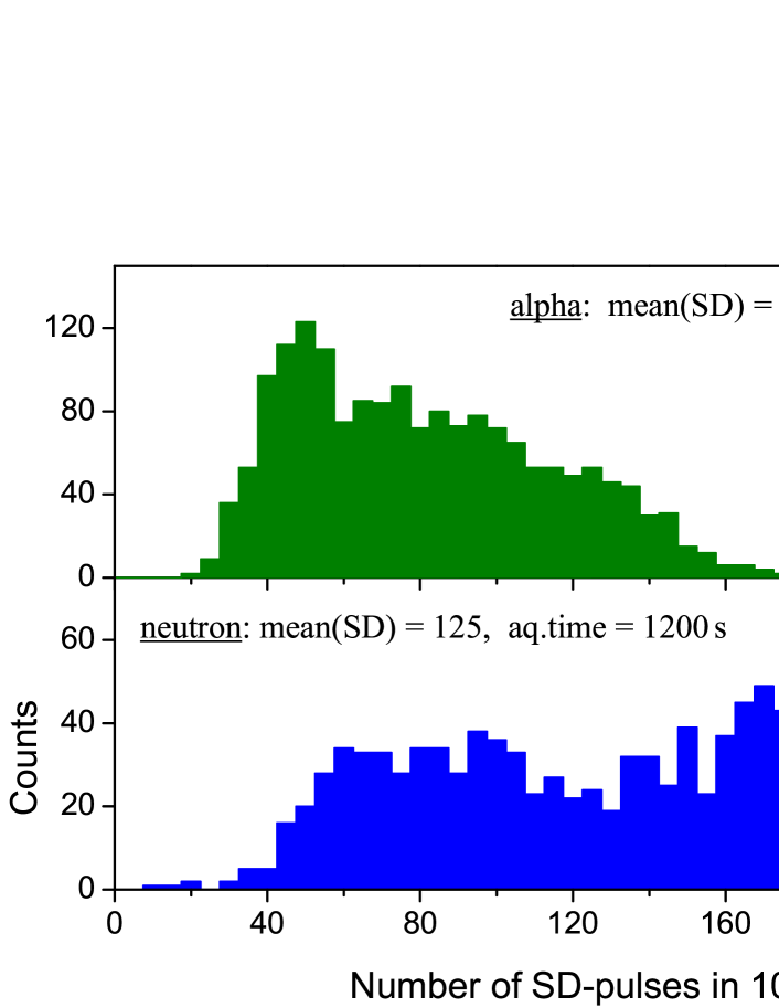
Figure 8 shows the distributions of accumulated numbers of SD-pulses corresponding to the detection of alpha-particles and neutrons at gate(1) = 80 ns and N = 8. The SD-signal count accumulation time was set to the first 10 s of the detected events. This parameter (number of SD-counts) was obtained using the measuring capabilities of a LeCroy WaveRunner 640Zi DSO. In case of neutron detection the average number of photon counts is about 1.5 times larger. This fact allows us to consider the trigger efficiency determined above in measurements with the alpha source as a conservative estimate for the trigger efficiency with neutrons.
Summary
The feasibility of using Silicon Photomultipliers operated at room temperature for individual channel readout in multi-channel neutron detection systems utilizing ZnS:6LiF scintillation screens is demonstrated. An efficient light collection is achieved by uniformly distributing mm WLS fibers within the volume of the scintillator. A signal processing scheme based on the acceptance of all of the SiPM pulses (generated either by scintillation photons or thermally) with a subsequent efficient suppression of the dark counts is presented.
With a prototype singe-channel detection unit using a SiPM with dark-count rate of MHz the background count rate of Hz and the trigger efficiency for alpha-particles of % are demonstrated. For neutrons a higher trigger efficiency is to be expected due to the larger amount of photons from one single neutron absorption process.
Optimization of the design of the scintillator / WLS fiber structure (type of used fibers, fiber spacing both within one layer and between the layers) as well as a full characterization of the detector with a neutron source will be subjects of further investigations and discussed elsewhere.
Acknowledgments
We express our gratitude to Andreas Hofer (Detector Group of the Laboratory for Particle Physics) for designing and building our prototype detection units.
References
- [1] N.J. Rhodes et al., Nucl. Instr. and Meth. A 392 (1997) 315.
- [2] K. Sakasai et al., Nucl. Instr. and Meth. A 600 (2009) 157.
- [3] T. Nakamura et al., Nucl. Instr. and Meth. A 686 (2012) 64.
- [4] T. Nakamura et al., Nucl. Instr. and Meth. A 741 (2014) 42.
- [5] B. Dolgoshein et al., Nucl. Instr. and Meth. A 563 (2006) 368.
- [6] G. Collazuol et al., Nucl. Instr. and Meth. A 628 (2011) 389.
- [7] E.S. Kuzmin et al., Journal of Neutron Research 10(1) (2002) 31.
- [8] J.-B. Mosset et al., arXiv:1309.6885v1
- [9] http://www.hamamatsu.com
- [10] Y. Musienko et al., Nucl. Instr. and Meth. A 581 (2007) 433.
- [11] http://www.appscintech.com
- [12] http://www.eljentechnology.com
- [13] http://www.kuraray.co.jp