Interface magnetic moments enhancement of FePt-L10/MgO(001): an study
Abstract
The interface between FePt–L10 and MgO(001) alloys has been studied using density functional calculations. Because the stacking of the face-centered tetragonal L10 phase is formed by alternating Fe and Pt planes, both the Fe- and Pt-terminated contact layers were studied. Furthermore, due to the large mismatch between the in-plane lattice constants of both systems, we have chosen some common values for both alloys in order to explore in detail the adsorption energy, the electronic structure and the interface magnetism. The adsorption energy has been calculated by subtracting the energy of clean FePt and MgO alloys from the total energy. The preferred adsorbed geometric sites for Fe/Pt atoms are when they lie on of the O species, having a smaller adsorption energy for the remaining positions. We found that expanding the MgO lattice enhances the magnetic moment of the Fe species but the Pt moments remain almost constant.
I Introduction
The face-centered tetragonal (fct) L10 phase of the 3d–5d binary based alloys such as FePt have recently been the subject of much attention because of their potential applications for the fabrication of ultrahigh density data recording media weller_para . These alloys present high values of the magnetocrystalline anisotropy (MAE) constants (7107 ergs/cm3) Pirama ; ivanov along the –axis, a preferred orientation direction (easy axis). These high values of the anisotropy are necessary to overcome the superparamagnetic limit Yan in order to avoid the loss of recorded information. There are several methods to achieve the desired ferromagnetic structures such as the alternating monatomic layer deposition of Fe and Pt Shima or alternatively the room temperature deposition of disordered fcc FePt on an underlayer followed by annealing at around 600 ∘C to induce a phase transformation from fcc to fct L10 stacking. Extensive studies such as the effect of the alloying composition and growing FePt films on various underlayers, for instance MgO, Chen PtMn, Chiang or Si, Wu among others, have been carried out to optimize the microstructure and the magnetic properties as well as decreasing the processing temperature Xu . For practical purposes there are still some challenges, for example the ordered FePt grains with perpendicular (001) crystallographic orientation have to be magnetically decoupled from each other for which some materials are added in the fabrication process (see Ref. Peng and references therein). The use of MgO as an underlayer has some practical drawbacks such as its elevated costs, but the MgO single crystalline substrate promotes the out-of-plane anisotropy in contrast to other substrates which tend to promote in-plane anisotropy. Perumal Additionally, because the MgO lattice parameter is larger than that of FePt, it can easily promote the to remain perpendicular during the growing process, thus reducing the in-plane variants.
From a theoretical point of view the transition metal (TM) binary compounds have been extensively studied in the past decade in their bulk phases, slabs, Chepulskii2012 gas phases, Cuadrado ; antoniak ; rollman and interfaces Zhu1 , however only a few theoretical studies based on FePt–L10/MgO(001) interfaces have been carried out Zhu1 ; Zhu2 . In this work we scan different configurations for this interface in a systematic investigation of the potential adsorption geometries, namely, the Fe-/Pt-termination, different atomic adsorption sites and the influence within the electronic structure of changes in the MgO(001) lattice constant, .
The paper is structured as follows: The employed theoretical tools are explained briefly in section II. In section III.1 we will summarize the final geometric structures as well as the related adsorption energies. The electronic study is presented in the section III.2 and the magnetic behaviour in III.3. The conclusions and future work are in section IV.
II Theoretical Methods
We have undertaken geometrical, electronic and magnetic structure calculations of the FePt–L10/MgO(001) interface by means of DFT using the SIESTA siesta code. To describe the core electrons we have used fully separable Kleinmann-Bylander kb and norm-conserving pseudopotentials (PP) of the Troulliers-Martins tm type. Our DFT based calculations have been performed within the generalized gradient approximation (GGA) for the exchange correlation (XC) potential following the Perdew, Burke, and Ernzerhof (PBE) version pbe . To address the description of magnetic systems, pseudocore (pc) corrections were used to include in the XC terms not only the valence charge density but also the core charge cc . In order to ease the convergence of three center integrals with the size of the real space grid, is replaced by a pseudo-core charge density, , which equals the real core charge density beyond a given radius, , while close to the nuclei it becomes a smooth function. The radius should be chosen small enough to ensure that the overlap region between the valence and the core charges is fully taken into account. Based on previous studies of the binary alloys LS-paper , we have chosen for this radius the values of rpc(Fe) = 0.6 Bohrs and rpc(Pt) = 1.0 Bohrs, ensuring that the overlap region between the valence and the core charge is fully taken into account. As the basis set, we have employed double-zeta polarized (DZP) strictly localized numerical atomic orbitals (AO). The confinement energy, , defined as the energy cost to confine the wave function within a given radius, was set to 100 meV. The so–called electronic temperature –kT in the Fermi-Dirac distribution– was set to 50 meV. In all the cases we ensured convergence of the Brillouin Zone (BZ) integration by considering a k–supercell of (16x16), i.e., 256 k-points. Real space three-center integrals are computed over a three-dimensional grid with a resolution of 900 Ry, a mesh fine enough to ensure convergence of the magnetic properties.
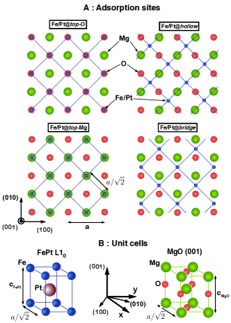
The interface system is described by a two-dimensional periodic slab comprising eight MgO(001) plus eight FePt–L10 oriented layers. The L10 structure stacking is a fct phase in which there are alternate planes of Fe and Pt along the (001) direction. Because of this, there arises the possibility of having two kinds of interfaces between FePt–L10 and MgO(001): Fe-terminated (Fe/MgO) and Pt-terminated (Pt/MgO). Furthermore we can see in the Fig. 1A schematically the top views of four possible initial configurations, first and second rows. The small red and big green spheres represent the MgO alloy and the blue represent the first contact plane of the FePt alloy, either Fe or Pt. On the other hand, in the Fig. 1B the unit cells are shown following the same atomic nomenclature as in A but now explicitly the Pt atom presents a bigger size than the Fe ones. Specifically, depending whether the Fe/Pt atoms lie on , or at positions, we have named the configurations as follows: on of O (Fe/Pt@-O), on of Mg (Fe/Pt@-Mg), at (Fe/Pt@) and in positions (Fe/Pt@). Metastable adsorption structures were obtained after relaxing the different proposed models to local minima until forces on atoms were smaller than 0.03 eV/Å. During the minimization process, just two layers of each material were allowed to relax leaving the rest of the atoms in the slab fixed to their bulk positions.
The presence of two kinds of atoms in the FePt-L10 phases generates a vertical distortion so that its structure is defined by two quantities, the in-plane lattice parameter, , and the out-of-plane constant, , whose bulk experimental values are =3.86 Å and =0.98. The magnesium oxide structure can be described as two inter–penetrating fcc lattices displaced by along the body diagonal of the conventional cube and the bulk experimental value for its lattice parameter is =4.22Å. We observe that the in-plane mismatch between both alloys is 8.5. Because of this and in order to scan more geometrical possibilities we have used the four common in-plane lattice values: 4.00Å, 4.05Å, 4.10Å and 4.30Å. The last value corresponds to the optimized lattice constant for the bulk MgO under GGA and it has been taken into account to address how the FePt geometry and magnetic properties change not only with intermediate common values but also with an optimized value. According to the changing , the distance between planes will vary too, so it was necessary to optimize the parameter for each lattice value. The results of both bulk systems and their corresponding out-of-plane distortions are for MgO: c/a = 1.14, 1.12, 1.10, 1.00 and for FePt: c/a = 0.92, 0.90, 0.88, 0.75 for a = 4.00Å, 4.05Å, 4.10Å and 4.30Å, respectively.
III Results
III.1 DFT structural relaxations
| Fe-terminated | Pt-terminated | ||||||||||||
|---|---|---|---|---|---|---|---|---|---|---|---|---|---|
| Site | a (Å) | Eads | MMM | MMNM | Eads | MMM | MMNM | ||||||
| @-O | 4.00 | 0.89 | 2.23 | 3.22 | 0.24 | 0.57 | 2.55 | 3.26 | 0.25 | ||||
| 4.05 | 0.93 | 2.21 | 3.26 | 0.25 | 0.60 | 2.57 | 3.30 | 0.26 | |||||
| 4.10 | 0.97 | 2.19 | 3.29 | 0.25 | 0.62 | 2.56 | 3.34 | 0.26 | |||||
| 4.30 | 1.14 | 2.16 | 3.34 | 0.21 | 0.74 | 2.47 | 3.39 | 0.20 | |||||
| @-Mg | 4.00 | 0.19 | 3.30 | 3.26 | 0.25 | 0.22 | 3.16 | 3.27 | 0.25 | ||||
| 4.05 | 0.20 | 3.47 | 3.30 | 0.25 | 0.22 | 3.13 | 3.30 | 0.25 | |||||
| 4.10 | 0.20 | 3.51 | 3.33 | 0.25 | 0.23 | 3.14 | 3.34 | 0.26 | |||||
| 4.30 | 0.22 | 3.54 | 3.37 | 0.21 | 0.29 | 3.07 | 3.40 | 0.21 | |||||
| @ | 4.30 | 0.57 | 2.47 | 3.36 | 0.21 | 0.45 | 2.68 | 3.40 | 0.21 | ||||
| @ | 4.30 | 1.13 | 2.17 | 3.34 | 0.21 | 0.70 | 2.51 | 3.39 | 0.20 | ||||
In the table 1 we present the results of the interface adsorption energies Eads, the perpendicular bond distance computed as the difference of the MgO plane and the Fe/Pt one: (Ai)=– [Ai=Fe,Pt; Bi=Mg,O] and the total magnetic moment (MM) per magnetic/non-magnetic species for all the configurations. Two different contact layers, namely, Fe- and Pt-termination have been taken into account with a common in-plane lattice constant ranging from 4.00 to 4.30Å. The adsorption energies were evaluated after subtracting from the total energy of the FePt+Mg(001) bilayer the energy of the two clean metallic slabs.
A general tendency of all @ relaxed structures is that as the in-plane lattice constant expands from 4.00Å to 4.30Å the Eads increases significantly. It is noticeable that for the Fe-terminated configuration on top of O (first four values in the third column of Table 1), the average adsorption energies are larger by 0.35, 0.87 and 0.74 eV compared to those of Pt@-O, Fe@-Mg and Pt@-Mg sites, respectively. Consequently, the bond between the FePt and MgO will be stronger for the Fe@-O, with decreasing stability for the other cases, with Fe@-Mg having the lowest stability. In order to scan more possible accommodation sites for Fe/Pt atoms we also studied Fe/Pt@ and Fe/Pt@ adsorption configurations (see Fig. 1A) considering only the GGA optimized value of . The Eads values in these cases are between of those of Fe/Pt@-O/-Mg sites, providing a weak chemical bonding for FePt. Regarding the Fe/Pt@ case and after relaxing the interfaces, we found that the strong Fe/Pt-O chemical interaction means that the Fe/Pt@ atoms move closer to the @-O positions. In fact, the equilibrium position for the Fe/Pt atoms is only 0.2 Å distant from their @-O positions.
We also notice, by inspection of the table, that Eads values are quite similar in both cases. Related to the Eads, the bond distance, (Ai), will depend on the strength of the bond: the higher the adsorption energies the smaller distances and stronger bonding will arise. This implies that the Fe/Pt planes will be closer to the MgO contact layer resulting in a complex rearrangement of the charge, changing the final values of the magnetic moments and hence the magnetic behaviour. Except for the case of Fe@-Mg, where Eads remains approximately constant, the interlayer bond distance decrease as increases. We will discuss in detail in section III.3 the behaviour of the magnetic moments. As a global tendency we can say that the MMM values are augmented as is increased, by an average amount of 0.13 and remain almost constant for MMNM with the special characteristic reduction of these values for =4.30Å.
III.2 Density of states and hybridisation study
We display in Fig. 2 the evolution of the spin-resolved density of states (DOS), projected on the Fe/Pt interface atoms, for Fe- and Pt- terminated FePt layers. For both cases results are presented for the @-O and @-Mg adsorption sites. The next FePt–L10 layers after the contact layer (Pt atoms for Fe-termination or Fe for Pt-termination) are not shown here because changes in the electronic states are not significant beyond the interface layer. The three different colours in each graph depict the Fe/Pt DOS of the bilayer (filled turquoise curve), the Fe/Pt for the clean surface (thick solid pink line) and the atomic DOS projection of the atoms in their bulk phase (thin solid black line). Inside each graph the MM values appear on the bottom left corner just for the bilayer configurations together with a positive (negative) value within parenthesis that represents the increase (decrease) of the local MM compared to the Fe/Pt atomic bulk values.
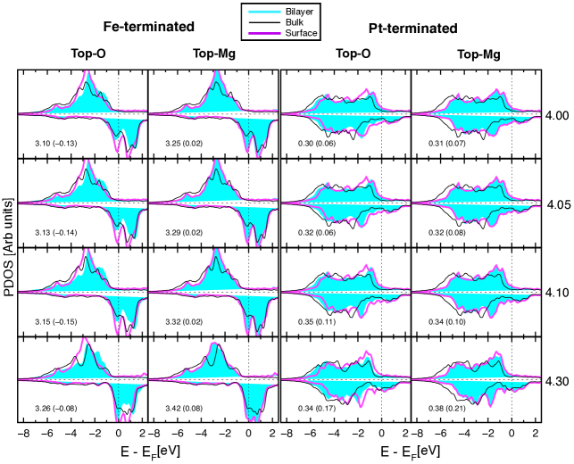
A first inspection of Fig. 2 shows that the DOS at the interface layer is significantly affected for contact with both MgO and vacuum. Further inspection of the DOS for the four rows (O and Mg adsorption sites) regarding both the Fe-/Pt-terminations, shows that, when the Fe/Pt atoms lie @-Mg rather than @-O, the interface Fe/Pt PDOS profile is almost the same as those of clean surfaces either spin-up or spin-down. Consequently the surface states of the FePt alloy will not be altered significantly. As a result, when Fe/Pt are @-Mg the FePt termination behave similarly to a vacuum termination irrespective of the contact with MgO. This confirms the significant difference of 0.74 eV between the adsorption energies regarding the Mg or O sites (see table 1). Then, as we pointed out in the previous section, the bonding between Fe/Pt and Mg atoms will be weaker than with the O atoms.
The abrupt termination of the FePt–L10 alloy in the clean surfaces and in the interface of the bilayer induces within the electrons a rearrangement which is distinct from that in the bulk phase Although the Fe/Pt coordination will be the same for the whole system, the environment will be modified compared to that of the bulk, given that now the Mg and O atoms are in the former positions of the Fe/Pt species. This is noticeable if we inspect the DOS of the Fe-termination (first two columns). In the bulk case the up-states are located in an energy range of 5 eV, i. e., from -1 to -6 eV for the @-O/-Mg configurations. Despite the fact that the DOS of the interfaces and clean surfaces are quite similar to those of the bulk, their states are located closer to a pronounced peak at 3 eV weakly present in the bulk, leading to a narrowing of both the bilayer and clean surface d-bands.
The fact that the spin-up and spin-down black curves have a small shift to lower energy values, compared to the pink and turquoise curves, in the last two columns of Fig. 2 (Pt-termination) can be explained by inspection of the Mulliken population of the bulk FePt. This shows that the bulk atomic species are more charged than the other two systems by an average of 0.2 e/at.
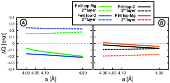
The analysis of the data shows that the charge transfer between the atoms (orbitals) belonging to an interface is of paramount importance. It gives us a way to understand the hybridisation between atoms and how this influences the bond strength and the magnetic behaviour. In figure 3 it shown that the difference in charge transferred between the magnetic and non–magnetic species is larger compared to the bulk phases. In figure 3A, situating the Fe atoms in the @-O position (blue solid line) increases the amount of charge given to the Pt layer (dashed blue line) and to the first MgO plane by an average of 0.18 e/at. The same situation occurs when the Fe is @-Mg (solid green line) though the effect is smaller. The dispersion ranges from 0.07 e/at up to almost 0.2 e/at for 4.30Å. When the Pt contact layer is @-O (black solid line) it behaves in a similar way to bulk phase so that only for the 4.30Å lattice spacing is the amount of excess charge transferred to the Pt is significant at 0.08 e/at. Similar behavior is shown when comparing the Fe contact configuration in A. The Fe atoms in this case (black dashed line) are responsible for the charge transfer, having almost a constant contribution along all the values. Finally, the charge transferred to the Pt atoms @-Mg (red solid line) shows very little change with respect to the bulk phase, increasing only slightly for the large values. The increase is clear however for the Fe atoms: again they lose more charge than in the bulk. In summary, the presence of the MgO changes significantly the FePt-L10 behavior depending on whether the contact layer is Fe or Pt and also where the Fe/Pt atoms are located after relaxation. This implies different kinds of hybridisation between 3 and 5 orbitals of these Fe and Pt atoms respectively.
In order to link the MM behaviour with the DOS curves we also observe that in Table 1 the MM values of the Fe atoms increase by 0.13 with the in-plane lattice spacing for all the configurations. This small enhancement of the MMM can be observed in the DOS curves noting that the down-state peaks below the Fermi level at 0.2 eV for 4.00Å move to lie just at the Fermi level for 4.30Å resulting in a deficit of down-states compared to the up-states which are almost constant with . Finally, the DOS projected onto the interface plane of the MgO alloy (not shown here) does not change significantly, there is only some charge transfer among the interface resulting in a very small value of the local MM values (see Sec. III.3).
III.3 Interface magnetism: Magnetic Moments
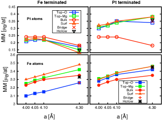
We provide in Fig. 4 the magnetic moment (MM) values per atom as a function of the in-plane lattice parameter for all the configurations studied in this work. The global trend of the MM values of the Fe atoms for both Fe-/Pt-terminations (bottom row) is an enhancement of around 0.13/at as the lattice increases from 4.00Å to 4.30Å. Although this behaviour is shared by all the adsorption positions, i.e., @(top-O, top-Mg,hollow,bridge) there is just an increase of 0.06/at in the bulk case (filled red circles) when =4.30Å compared to the smaller lattice considered. The values of the MM of the Pt atoms for both Fe-/Pt-terminations (first row) are enhanced as are those of the Fe atoms when increases up to =4.15Å. However the MM decreases (increases) for the Fe-terminated alloys (Pt-terminated) for larger . Inspecting the MM values vertically (common lattice) either @top-O or @top-Mg, blue and green filled squares, respectively, we observe that the dispersion between these two adsorption sites is about 0.15/at. It is evident after inspecting table 1 that the lower distance between the Fe/Pt:MgO layers gives the higher adsorption energy. This behaviour plays an important role in the net MM/at values since the charge rearrangement between down and up states of the system promotes the reduction or the increase of the MM/at depending if the adsorption site is @top-O or @top-Mg, respectively. Completing the magnetic study we have added dots to represent the MM values for the Fe/Pt@(,) sites, black asterisks and red crosses, respectively. Their MM values do not have significant changes regarding others with same value, they are almost the same as those obtained for the Fe/Pt@-O configurations.
| Fe-terminated | Pt-terminated | ||||||||
|---|---|---|---|---|---|---|---|---|---|
| Site | a(Å) | MMMg | MMO | MMMg | MMO | ||||
| @-O | 4.00 | -0.11 | 0.03 | -0.03 | 0.03 | ||||
| 4.05 | -0.12 | 0.03 | -0.03 | 0.03 | |||||
| 4.10 | -0.12 | 0.03 | -0.04 | 0.03 | |||||
| 4.30 | -0.10 | 0.04 | -0.03 | 0.04 | |||||
| @-Mg | 4.00 | -0.00 | 0.02 | -0.03 | 0.02 | ||||
| 4.05 | -0.02 | 0.01 | -0.03 | 0.02 | |||||
| 4.10 | -0.02 | 0.01 | -0.03 | 0.02 | |||||
| 4.30 | -0.01 | 0.01 | -0.04 | 0.03 | |||||
| @ | 4.30 | -0.05 | 0.04 | -0.02 | 0.04 | ||||
| @ | 4.30 | -0.10 | 0.04 | -0.03 | 0.03 | ||||
Finally we show in Table 2 the site resolved MM values of Mg and O atoms. Note that the Mg species favors the down states while the O sites exhibit the opposite behavior. The most significant difference between the distinct configurations occurs @-O adsorption sites since the MMMg are almost constant, at a value of -0.12 in comparison with the rest. The O species have an average constant value of 0.03 .
IV Conclusions and future work
We have carried out a first principles study of the FePt–L10/MgO(001) interface regarding different in-plane lattice constant values and the two possible FePt contact planes due to the L10 stacking. In addition we scanned the magnetic/electronic properties for different adsorption sites for a common Fe/Pt plane, namely, @(-O,-Mg,,). The adsorption energies provide a way to elucidate the preferential adsorption site and lattice constant value. The higher values were obtained for Fe@-O followed by those of the Pt@-O and also when the larger in-plane lattice constant has been taken into account. The stronger chemical bonding then occurs for these configurations having a significant overlap between the -bands and the MgO orbitals. Additionally, we found that as the Eads decreases(increases) the MMM values augment(diminish) however the induced MM within the Pt species is not significantly affected by this variation. The use of GGA as the XC could overestimate the bonding between these materials giving the possibility that from an experimental point of view, the bond distance would be shorter and hence the adsorption energy higher.
A useful compliment to the discussion of atomic hybridisation at the end of section III.2 would be a study of the up/down population of the -orbitals. It is however beyond the scope of this work to include such details and instead we have only explored qualitatively the atomic spin-resolved population to understand how the spin charge influences the magnetic behavior. The spin electronic analysis confirms the results of the DOS calculations (Fig. 2). It shows that with increasing lattice constant, , the amount of up (down) charge increases (decreases) leading to an enhancement of the MM values.
In addition, figure 4 shows that there is a constant difference of 0.25/at in the MM values for different adsorption positions (see separate blue and green symbols in the Fe-terminated configuration). The lowest adsorption energy value is shown for the Fe@-O and hence this is the most stable configuration. This means that the hybridisation between the MgO and the Fe contact layer is stronger, reducing the MM values and promoting a bigger charge transfer among atoms. For the Pt-terminated configurations, as was pointed out in section III.1, the adsorption energy is smaller and the orbital hybridisation is smoother, therefore the MM values are close to each other for all values of .
It has recently been shown fefept that the site-resolved Magnetocrystalline Anisotropy Energy (MAE) of FePt is associated with the Fe sites. This is due to the strong 3d Fe – 5d Pt hybridisation through which the spin-orbit interaction on the Pt atoms is transferred to the electronic states at the Fe sites. Consequently, the complex charge transfer processes at the FePt/MgO interface predicted here might be expected to be reflected in changes in the FePt MAE at the MgO interface. However, the charge transfer effects seem rather localized to the FePt/MgO interface, so the effect might be significant only for ultrathin films. However, this is an interesting possible effect, which is beyond the scope of the current work but certainly worthy of further investigation.
V Acknowledgments
The authors are grateful to Dr T.J Klemmer for helpful discussions. Financial support of the EU Seventh Framework Programme under grant agreement No. 281043, FEMTOSPIN, and Seagate Technology is gratefully acknowledged.
References
- (1) D. Weller and A. Moser, IEEE Trans. Magn., 36, 10 (1999).
- (2) N. Piramanayagam J. Appl. Phys. 102, 011301 (2007)
- (3) O. A. Ivanov, L. V. Solina, V. A. Demshina and L. M Magat Fiz. Metal Metalloyed 35, 92 (1973).
- (4) M. L. Yan, H. Zeng, N. Powers, and D. J. Sellmyer J. Appl. Phys. 91, 8471 (2002)
- (5) T. Shima, T. Moriguchi, S. Mitani, and K. Takanashi Appl. Phys. Lett. 80, 288 (2002)
- (6) J. S. Chen, B. C. Lim, J. F. Hu, Y. K. Kim, B. Liu, and G. M. Chow Appl. Phys. Lett. 90, 042508 (2007)
- (7) C. C. Chiang, C.-H. Lai, and Y. C. Wu Appl. Phys. Lett. 88, 152508 (2006)
- (8) Y. C. Wu, L. W. Wang, and C. H. Lai, Appl. Phys. Lett. 91, 072502 (2007)
- (9) Y. F. Xu, J. S. Chen, and J. P. Wang Appl. Phys. Lett. 80, 3325 (2002).
- (10) Yingguo Peng, Jian-Gang Zhu, and David E. Laughlin J. Appl. Phys. 99, 08F907 (2006).
- (11) A. Perumal, Y. K. Takahashi, T. O. Seki, and K. Hono Appl. Phys. Lett. 92, 132508 (2008).
- (12) Roman V. Chepulskii and W. H. Butler Appl. Phys. Lett., 100, 142405, (2012).
- (13) R. Cuadrado, and R. W. Chantrell Phys. Rev. B 86, 224415 (2012)
- (14) Carolin Antoniak, Markus E. Gruner, Marina Spasova, Anastasia V. Trunova, Florian Römer, Anne Warland, Bernhard Krumme, Kai Fauth, Shoheng Sun, Peter Entel, Michael Farle and Heiko Wende Nature Communications 2, 528 (2011).
- (15) Georg Rollman, Markus E. Gruner, Alfred Hucht, Ralf Meyer, Peter Entel, Murilo L. Tiago and James R. Chelikowsky Phys. Rev. Lett. 99, 083402 (2007).
- (16) Wanjiao Zhu, Yaowen Liu, and Chun-Gang Duan Appl. Phys. Lett. 99, 032508 (2011)
- (17) Wanjiao Zhu, Hang-Chen Ding, Shi-Jing Gong, Yaowen Liu, and Chun-Gang Duan J. Phys.: Condens. Matter. 25, 396001 (2013)
- (18) J.M. Soler, E. Artacho, J.D. Gale, A. García, J. Junquera, P. Ordejón and D. Sánchez-Portal, J. Phys.: Condens. Matter, 14, 2745, (2002).
- (19) L. Kleinman and D. M. Bylander, Phys. Rev. Lett., 48, 1425, (1982).
- (20) N. Troullier and J. L. Martins, Phys. Rev. B, 43, 1993, (1991).
- (21) J. P. Perdew, K. Burke and M. Ernzerhof, Phys. Rev. Lett., 77, 3865, (1996).
- (22) S.G. Louie, S. Froyen and M.L. Cohen, Phys. Rev. B, 26, 1738 (1982).
- (23) R. Cuadrado and J. I. Cerdá J. Phys.: Condens. Matter 24, 086005 (2012).
- (24) C J Aas, P J Hasnip, R Cuadrado, E M Plotnikova, L Szunyogh, L Udvardi and R W Chantrell Phys Rev B, 88, 174409 (2013).