Unidirectional direct current in coupled nanomechanical resonators by tunable symmetry breaking
Abstract
We investigate theoretically the non-linear dynamics of the most fundamental component of a bistable coupled oscillator. Under a weak radio frequency excitation, the resonator is parametrically tuned into self-sustained oscillatory regimes. The transfer of electrons from one contact to the other is then mechanically assisted, generating a rectified current. The direction of the rectified current is, in general, determined by the phase shift between the mechanical oscillations and the signal. However, we locate intriguing parametrical regions of uni-directional rectified current, resulting from spontaneous parity-symmetry breaking. In these regions, a dynamical symmetry breaking is induced by the non-linear coupling of the mechanical and electrical degrees of freedom. The achieved unstable regime favors then a uni-directional response, resulting in a direct, positive electric current. When operating within the Coulomb blockade limit, the charge balance in the oscillators perturbs drastically the mechanical motion, causing large accelerations that further enhance the shuttle response. Our results suggest a practical scheme for the realization of a self-powered device in the nanoscale.
pacs:
85.85.+j ; 05.45.Xt ; 05.45.–a; 73.23.HkBifurcations are closely linked to catastrophes in systems operating in nonlinear regime. In general terms, a system experiences a catastrophe when a smooth change in the value of a parameter results in a sudden change in the response of the system. The response is then termed as parametrically driven. Interest in parametrically driven nonlinear dynamics of nano-electromechanical systems (NEMS) has grown rapidly over the last few years villanueva_nano ; midtvedt_nano ; requa_apl . NEMS offer the possibility to realize nanomechanical switches subramanian_acs , circuits blicknjop ; mahboob ; roukesNMC ; zhou ; palomaki , electronic transducers roukes_nano ; bartsch_acs , current rectifiers pistolesi ; ahn , or high-sensitive charge scheible_apl04 , spin rugarNature ; palyi ; chotorlishvili and mass sensors rugarPRL ; roukesMD ; puller , as well as the general study of nonlinear dynamics of oscillators and resonators leturceq ; vonoppen ; drews ; faust_nature ; faust ; cohen . In these systems charge transport is mechanically assisted and typically driven by an RF excitation of tunable intensity and frequency. When the mechanical degrees of freedom couple to the RF excitation, the system may enter a regime of strong nonlinear response as the frequency and the intensity of the excitation are slowly varied, hence, parametrically driven. Understanding behavior of these devices in the nonlinear regime can thus point to strategies for engineering self-powered NEMS-based devices wang .
Back in 1998 Gorelik et al. gorelik proposed a nanomechanical transistor based on a vibrating shuttle between two contacts. The mechanical motion of the shuttle perturbs the charge balance, causing accelerations that could further enhance the response of the shuttle. Scheible et al. scheible_apl04 experimentally realized such an electron shuttle in the form of a single nanopillar vibrating in a flexural mode, and observed a frequency dependent ratchet behavior. Following these experimental results, Pistolesi et al. pistolesi showed theoretically that the single electron shuttle can indeed act as a rectifier. More recently, Kim et al. ck ; ck2 ; kimprada_prl realized a nanomechanical shuttle capable of transferring electrons mechanically at room temperature in the Coulomb blockade regime. Their prototype consisted of two coupled Si nanopillars with a metallic island on top, as depicted in Fig. 1(a). The nanopillars are placed between two electrodes operating at high frequencies (0.1 GHz). One of the great advantages of this system is that cotunneling events are dramatically suppressed in a flexural oscillatory mode where the center of mass is at rest [see Fig. 1(a)]. Another is the obtention of a rectified dc signal resulting from spontaneous symmetry breaking ck ; ahn .
In this letter, we investigate the dynamics of the most fundamental component for the realization of bistable oscillators: a double coupled shuttle NEMS. In previous work by Ahn et al. ahn , the symmetry on the phase portraits of the solutions prevented a preferred direction for the current. However, we report here on spontaneous parity-symmetry breaking due to the non-linear coupling of the mechanical and electrical degrees of freedom. The parity-symmetry breaking results in the obtention of uni-directional direct currents. We demonstrate that parametrically controlled current flow and largely amplified response excel the double shuttle as an optimal device. We explore the parametric excitations within the Coulomb blockade limit, where abrupt, almost instantaneous increments and decrements of the charge difference in the nano-islands cause the average electrostatic force to change periodically in a square-wave fashion. Corresponding electromechanical instabilities open access to regimes of efficient charge pumping.
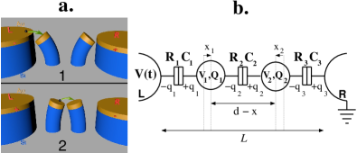
We start with a purely classical description of the circuit depicted in Fig. 1(b), as commonly found in literature pistolesi ; ahn ; gorelik . The mechanical degree of freedom (see Fig. 1) is described in terms of the relative displacement of two islands, . The dynamics within the quasi-adiabatic limit isacsson ; ahn is governed by the force exerted by an average electric field on the coupled oscillators, yielding
| (1) |
where , denotes the charge in the nanoislands, with , being the charge in the -th junction (see Fig. 1b), , with being the mass of a pillar and the oscillator eigenfrequency, denotes the dynamic damping, and is the distance between the electrodes. When the flexural modes of the nanopillars are excited, the resistances and mutual capacitances of each junction become sensitive to the displacements: and , where is the phenomenologically introduced tunneling length. We take and , consistent with previous results ck2 . Classical circuit analysis for the doubly charged shuttle gives , , , , allowing us to express the charge on each island in terms of the relative displacement prada_prb ,
| (2) |
with being the distance at rest between the shuttles. For small oscillations, , we expand Eq. (2) to third order. Eq. (1) becomes a modified Mathieu equation,
| (3) |
The dimensionless parameter quantifies the strength of the RF excitation, being the ratio of the electric () and mechanical forces (), with being the sprig constant. and relate to the applied voltage, . Throughout this work we take typical experimental values for = 0.1 and = 10-2. Within the weak electromechanical coupling limit, we parameterize the damping and the excitation strength with an arbitrarily small , and . We consider the resonant modes of the system, , where indicates the deviation from the natural resonance and is the winding number gorelik ; ck . This defines two time scales, the “stretched” time, , and the “slow” time, . We seek for steady oscillatory solutions, . Note that the mechanical oscillations can be alternatively expressed as , with , and defining the phase between the mechanical oscillations and the voltage. Following the Poincaré-Lindstedt method, we find linearized differential equations for the coefficients and prada_prb . Phase portraits and bifurcation diagrams are finally computed using evaluation routines matcont_auto .
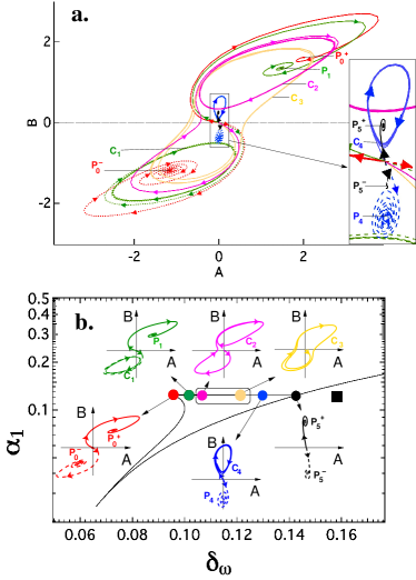
The phase portraits in the first unstable region are shown in Fig. 2(a), with the corresponding bifurcation diagram in Fig. 2(b). We chose six representing points along the parametric region of multiple stability. The associated phase portraits for each point are depicted in the insets [from Fig. 2(a)]. For these, the initial conditions were set near equilibrium, () for the solid (broken) traces, with arbitrarily small . The stable solutions are either attractor points, or cycles, , = 0,4. This results in electromechanical instabilities, in the sense that even if the pillars are initially nearly at rest, the electrostatic field will cause them to oscillate.
A pitchfork bifurcation is observed as we move from the left in the unstable region. The origin undergoes a transition, from a stable spiral to a saddle, where two non-trivial quasi-symmetric attractors appear (red traces, ). A supercritical Andronov-Hopf bifurcation causes one of the attractors to become an asymptotic curve (). Under further parametric variations a homoclinic bifurcation results in the birth of an unique limit cycle (, ). The asymmetry of the cycles result in an unique uni-directional current (see below). The rectangle marks the parametric region where uni-directional current is obtained.
The time-average direct current is then obtained for each asymptotic solution (, ) by integrating over a period the current across a junction,
| (4) |
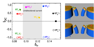
Here, is the center of mass displacement, which in most of the cases remains at rest ahn . The results are summarized in Fig. 3. An intuitive picture is sketched in the right insets of Fig. 3: for , the mechanical oscillations are always in phase with the voltage and electrons are flowing from left to right. However, for , the oscillators are out of phase, resulting in a negative rectified current. Outside the unstable region [black square of Fig. 2(b)] the trivial solution ( = = 0) is an attractor, and no direct current is observed. The sign of the current in typical bistable regions is then determined by the initial conditions, . This occurs in the red, green, blue and black traces of Fig. 2(a) where the sign of the phase is preserved, or, in other words, the trajectory remains in one semiplane ( or ). The corresponding stroboscopic plot is nearly symmetric in these bistable regions, so a positive or negative current can occur. On the contrary, for the magenta and yellow traces of Fig. 2(a), only one stable asymptotic orbit is found ( and ). The lack of symmetry of the stable phase portrait result in a positive (left-to-right) net current independently of the initial conditions. This occurs throughout the shaded region of Fig. 3. We note that the term in of Eq. (3), breaks the parity symmetry of the system: for a given solution , is not longer a solution. This term results from relative variation of the individual capacitances and resistances with the positions of the islands. Hence, we conclude that a dynamical symmetry breaking occurs due to the non-linear coupling of the mechanical and electrical degrees of freedom. We stress that the sign of the current is then parametrically controlled, suggesting an energy harvester for self-powered nanosystems li_n , or a nano-battery.
We now study the response on the relevant higher excitation frequency regions, i.e., in Eq. (4). For these, non-trivial solutions are found in the hatched areas indicated in Fig. 4. The case is of particular interest, as there exists a region in parameter space for which the origin becomes unstable. We then have a situation similar to the one of Fig. 2, within a different region of parameter space (see Fig. 3). For the cases , the origin of the phase plane is always an attractor, and hence, solutions with initial conditions in its proximity will vanish. However, another three attractors exist around a small area of the phase plane. Only when the initial conditions are close to these attractors, self-sustained oscillations are possible for this mode, but no electromechanical instabilities are found.
Next, we evaluate the dynamics of the islands within the Coulomb blockade limit, for which . In such a picture, abrupt increments and decrements of charge in the metallic islands occur almost instantaneously, separated by periodic time intervals weiss_zwerger . We use the master equation in terms of the excess electrons in the islands, ,
| (5) |
where the tunneling rate at the junction is given, according to the orthodox theory, by: , with being the decrease of free energy when the tunneling event occurs. We solve Eq. (5) by direct integration and get the occupation on each island, .
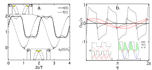
Fig. 5(a) shows the steady state solution for . As it can be seen, charge transfer occurs in the points of maximal deflection. The relative charge is nearly a square wave, . Inserting this expression into Eq. (1), we find, as before, linearized equations for the coefficients and of the oscillatory solutions,
| (6) |
with and . It is straight forward to see that Eq. (Unidirectional direct current in coupled nanomechanical resonators by tunable symmetry breaking) has one non-trivial attractor in the phase plane: In the absence of (), stable points are found only around subharmonics with = 1, 2 or 4, (, ) = , with , , and . In contrast, under a finite dc bias, the left-right symmetry is broken, and oscillatory solutions are found for any frequency at (, ) = . Let us focus now on the existence of a self-sustained oscillation. In an oscillatory mode, , the absorbed power by the oscillator per unit cycle is obtained by averaging over a period the last term of Eq. (1):
whereas the dissipated power is given by the damping term, . If this amount is larger than the dissipated power, , self-sustained oscillations kim_njp10 are expected. This occurs when max, with the appropriate phase . The amplitude of the oscillations could then be large enough to reach the Fowler-Nordheim tunneling limit scheible_prl , with a subsequent enhancement of the direct current due to field emission. Hence, under a finite dc bias, bands of instabilities occur for a particular value of the applied RF power, . Recent experimental data confirm the existence of such bands kimprada_prl .
To illustrate the importance of the phase between the mechanical oscillations and the RF signal, we compute the current for a few fictitious charge oscillations . Fig. 5(b) shows the average direct current (number of transferred electrons per cycle) as a function of the phase for four different charge oscillations, sketched in the lower-left inset. The function have the same period as the signal (solid traces) or twice (broken traces), and is a square wave (black) or a sinusoidal (red). It is evident from the figure that the square wave function with a periodicity twice the signal one (broken black traces) shows the most effective current on a broad relative phase range. A square-wave fashion variation is indeed known to pump energy more effectively than a sinusoidal variation butikov . This results in a rapid and enhanced response of the system, a very feature desired for industrial applications. The current is then negative for and positive elsewhere. We stress that the unidirectional current flow translates from the classical limit to the Coulomb blockade regime. The lower-right inset represents the RF signal (blue) and the corresponding (black). The averaged current per period is then proportional to the shaded areas, which is, for this particular choice of phase (=0), non-zero and positive.
In summary, we have theoretically studied a weakly AC driven coupled electron shuttle. We find multiple stability regions in parameter space with subsequent self-sustained oscillations generating a finite observable direct current. In the bi-stable regions, the sign of the current is bound to the relative phase of the mechanical oscillators and the signal. Subsequent dynamical symmetry breaking result in the obtention of uni-directional direct currents, a key feature in the implementation of a nano-battery. Within the Coulomb blockade regime, electromechanical instabilities are observed, which occur at any frequency in the presence of a dc bias. The tunability of the self-sustained oscillations and the uni-directionality of the current suggest a vast number of potential applications.
Acknowledgments: We are grateful to R. H. Blick and C. Kim for enlightening discussions. This work was supported by the program SB2009-0071, MAT 2011-24331, ITN grant 234970 and GrK 1286.
References
- (1) L. Guillermo Villanueva, Rassul B. Karabalin, Matthew H. Matheny, Eyal Kenig, Michael C. Cross, and Michael L. Roukes. Nano Letters, 11, 5054–5059 (2011).
- (2) D. Midtvedt, Y. Tarakanov, and J. Kinaret. Nano Letters, 11, 1439–1442 (2011).
- (3) M. V. Requa, and K. L. Turner. Appl. Phys. Lett., 88, 263508–263511 (2006).
- (4) A. Subramanian, A. R. Alt, L. Dong, B. E. Kratochvil, C. R. Bolognesi, and B. J. Nelson. ACS Nano, 3, 2953–2964 (2009).
- (5) R. H Blick, H. Qin, H.-S. Kim, and R. Marsland. New Journal of Physics, 9, 241 (2007).
- (6) I. Mahboob, K.and Fujiwara A. Flurin, E. Nishiguchi, and H. Yamaguchi. Nat. Commun., 2, 198 (2011).
- (7) M. D. LaHaye, J. Suh, P. M. Echternach, K. C. Schwab, and M. L. Roukes. Nature, 459, 960–964 (2009).
- (8) X. Zhou, F. Hocke, A. Schliesser, A. Marx, H. Huebl, R. Gross, and T. J. Kippenberg. Nat. Phys., 9, 1745-2473 (2013).
- (9) T. A. Palomaki, J. W. Harlow, J. D. Teufel, R. W. Simmonds, and K. W. Lehnert Nature 495, 210–214 (2013).
- (10) R. He, X. L. Feng, M. L. Roukes, and P. Yang. Nano Letters, 8, 1756–1761 (2008).
- (11) S. T. Bartsch, A. Lovera, D. Grogg, and A. M. Ionescu. ACS Nano 6 256–264 (2012).
- (12) K.-H. Ahn, H.C. Park, J. Wiersig, and H. Jongbae. Phys. Rev. Lett., 97, 216804–216807 (2006).
- (13) F. Pistolesi and R. Fazio. Phys. Rev. Lett., 94, 036806-036809 (2005).
- (14) D. V. Scheible and R. H. Blick. Appl. Phys. Lett., 84, 4632–4634 (2004).
- (15) D. Rugar, R. Budakian, H. J. Mamin, and B. W. Chui. Nature, 430, 329–332 (2004).
- (16) A. Pályi, P. R. Struck, M. Rudner, K. Flensberg, and G. Burkard. Phys. Rev. Lett., 108, 206811, (2012).
- (17) L. Chotorlishvili, D. Sander, A. Sukhov, V. Dugaev, V. R. Vieira, A. Komnik, and J. Berakdar, Phys. Rev. B 88, 085201 (2013).
- (18) D. Rugar and P. Grütter. Phys. Rev. Lett., 67, 699–702 (1991).
- (19) A. K. Naik, M. S. Hanay, W. K. Hiebert, X. L. Feng, and M. L. Roukes, Nat. Nano, 4, 445–450 (2009).
- (20) V. Puller, B. Lounis, and F. Pistolesi, Phys. Rev. Lett., 110, 125501 (2013).
- (21) R. Leturcq, C. Stampfer, K. Inderbitzin, L. Durrer, C. Hierold, E. Mariani, M. G. Schultz, F. von Oppen and K. Ensslin Nat. Phys., 5, 327–331 (2009).
- (22) G. Weick, F. Pistolesi, E. Mariani, and F. von Oppen. Phys. Rev. B, 81:121409, (2010).
- (23) A. Drews, et al., Phys. Rev. B, 85, 144417 (2012).
- (24) G. Cohen, V. Fleurov and K. Kikoin, Phys. Rev. B, 79, 245307, (2009).
- (25) T. Faust, J. Rieger, M. J. Seitner, J. P. Kotthaus, and E. M. Weig. Nat. Phys., http://dx.doi.org/10.1038/nphys2666, (2013).
- (26) T. Faust, J. Rieger, M. J. Seitner, P. Krenn, J. P. Kotthaus, and E. M. Weig. Phys. Rev. Lett., 109, 037205 (2012).
- (27) Z. L. Wang, and W. Wu, Angew. Chem. Int. Ed. 51, 11700 – 11721 (2012).
- (28) L. Y. Gorelik, A. Isacsson, M. V. Voinova, B. Kasemo, R. I. Shekhter, and M. Jonson . Phys. Rev. Lett. 80, 4526–4529 (1998).
- (29) C. Kim, J. Park, and R. H. Blick. Phys. Rev. Lett., 105, 067204–067207 (2010).
- (30) C. Kim, M. Prada, and R. H. Blick. ACS Nano, 6, 651–655 (2012).
- (31) C. Kim, M. Prada, G. Platero and R. Blick, Phys. Rev. Lett., 111, 197202, (2013).
- (32) A. Isacsson, L. Y. Gorelik, M. V. Voinova, B. Kasemo, R. I. Shekhter, and M. Jonson. Physica B: Condensed Matter, 255 150 – 163 (1998).
- (33) M. Prada, and G. Platero, Phys. Rev. B, 86, 165424 (2012).
- (34) MATCONT and AUTO–07p are numerical continuation software applications, freely available at http://www.matcont.UGent.be and http://indy.cs.concordia.ca/auto/.
- (35) J. Li, H. Yu, S. M. Wong, G. Zhang, X. Sun, P. G.–Q. Lo, and D.–L. Kwong Appl. Phys. Lett. 95, 033102–033104, (2009).
- (36) C. Weiss and W. Zwerger, Europhysics Letters, 47, 97 (1999).
- (37) H. S Kim, H. Qin, and R. H. Blick. New Journal of Physics, 12, 033008, (2010).
- (38) D. V. Scheible, C. Weiss, J. P. Kotthaus, and R. H. Blick. Phys. Rev. Lett., 93, 186801, (2004).
- (39) E. Butikov, Comp. Sci. Eng., 3, 76–83 (1999).