Counter operation in nonlinear micro-electro-mechanical resonators
Abstract
This paper discusses a logical operation of multi-memories that consist of coupled nonlinear micro-electro-mechanical systems (MEMS) resonators. A MEMS resonator shows two coexisting stable states when nonlinear responses appear. Previous studies addressed that a micro- or nano-electrical-mechanical resonator can be utilized as a mechanical 1-bit memory or mechanical logic gates. The next phase is the development of logic system with coupled multi-resonators. From the viewpoint of application of nonlinear dynamics in coupled MEMS resonators, we show the first experimental success of the controlling nonlinear behavior as a 2-bit binary counter.
1 Introduction
A micro-electro-mechanical resonator is a kind of devices fabricated using micro-electro-mechanical systems (MEMS) technology. A MEMS resonator substantially shows nonlinear responses at large excitation force. The dynamics of a nonlinear micro- or nano-electro-mechanical resonator is described by the Duffing equation [1, 2, 3, 4, 5, 6]. At nonlinear responses, an amplitude-frequency response curve bends toward higher or lower frequencies due to a hard or soft spring effect [7]. In particular, at a fixed excitation frequency in the hysteresis region, a nonlinear MEMS resonator has two stable periodic states and an unstable periodic state [8].
Recently, many studies focus on mechanical computation especially in micro- and nano-electro-mechanical resonators [1, 9, 10, 3, 11, 6, 12, 13, 14, 15, 16]. A mechanical memory device is a prospective application of nonlinear micro- or nano-electro-mechanical resonators [1, 9, 10, 3, 11, 6, 12]. Previous studies demonstrated that a micro- or nano-electro-mechanical resonator can be applied to execute mechanical logic gates [13, 14, 15, 16]. It is natural to expect that the next phase is the development of logic system with coupled multi-resonators.
This paper discusses a 2-bit binary counter [17] from the viewpoint of application of nonlinear dynamics in coupled MEMS memories. The authors experimentally showed the switching control between two coexisting stable states at a fixed excitation frequency in a nonlinear MEMS resonator [11]. Based on our previous study, here we show the first experimental success of the controlling nonlinear behavior in two coupled MEMS resonators as a 2-bit binary counter.
The overview of this paper is organized as follows. Sec. 2 presents two fabricated MEMS resonators and its four coexisting stable states. Sec. 3 explains the switching control system in the coupled nonlinear MEMS resonators. In Sec. 4, the switching control sequence of counter operation is experimentally achieved and examined.
2 MEMS resonator and its coexisting stable states
Figure 1 shows an electrostatically driven comb-drive resonator that was fabricated with silicon on insulator (SOI) technology [4, 18, 19]. When a MEMS resonator is actuated by applying an ac excitation voltage with a dc bias voltage between the mass and the electrodes, the mass vibrates in the –direction with a weak link to the –direction. In this paper, we utilize two comb-drive resonators.
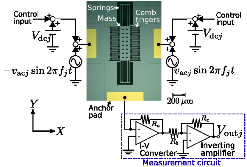
Figure 1 also presents a schematic diagram of the experimental setup in the differential measurement [20] for a single MEMS resonator as described in Ref. [11]. In the differential measurement for a single MEMS resonator, excitation force and output voltage are obtained by the following equations:
| (1) | |||||
| (2) |
where . Here denotes the excitation frequency of the -th MEMS resonator in the coupled system, the amplitude of the displacement, and the phase. denotes the comb number of each resonator, m the finger height, m the gap between the fingers, and F/m the permittivity. We set the dc bias voltage , the ac excitation amplitude , and the pressure at V, V, and around Pa at room temperature. The first (second) MEMS resonator is called Res. 1 (Res. 2) from here on.
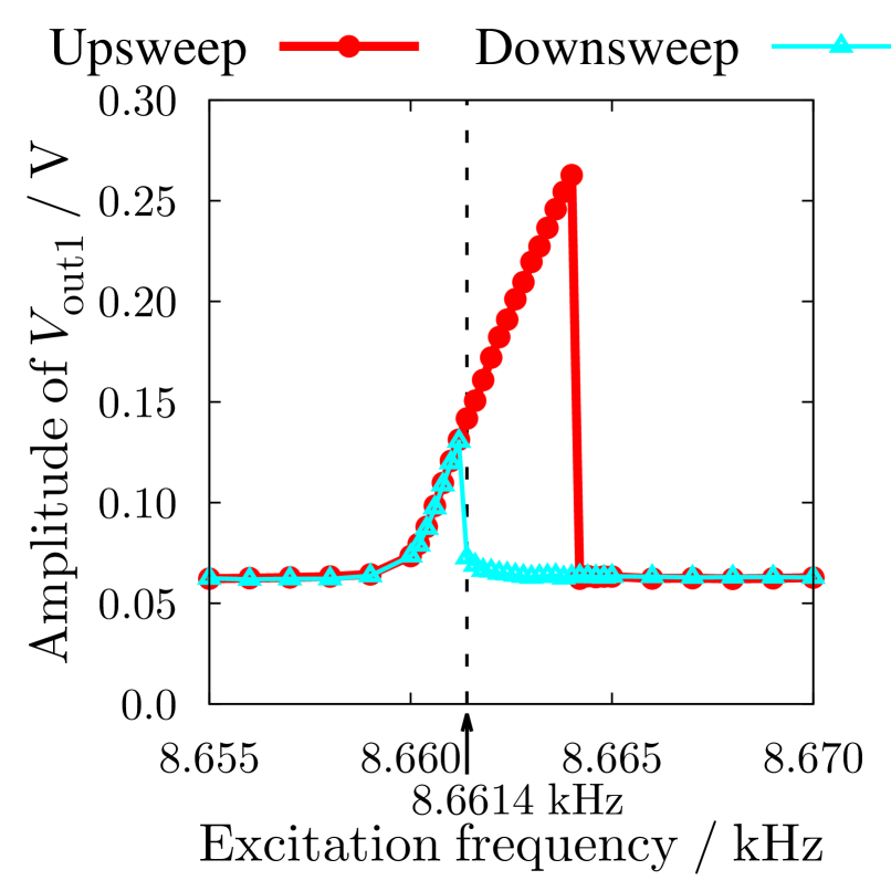
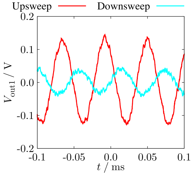
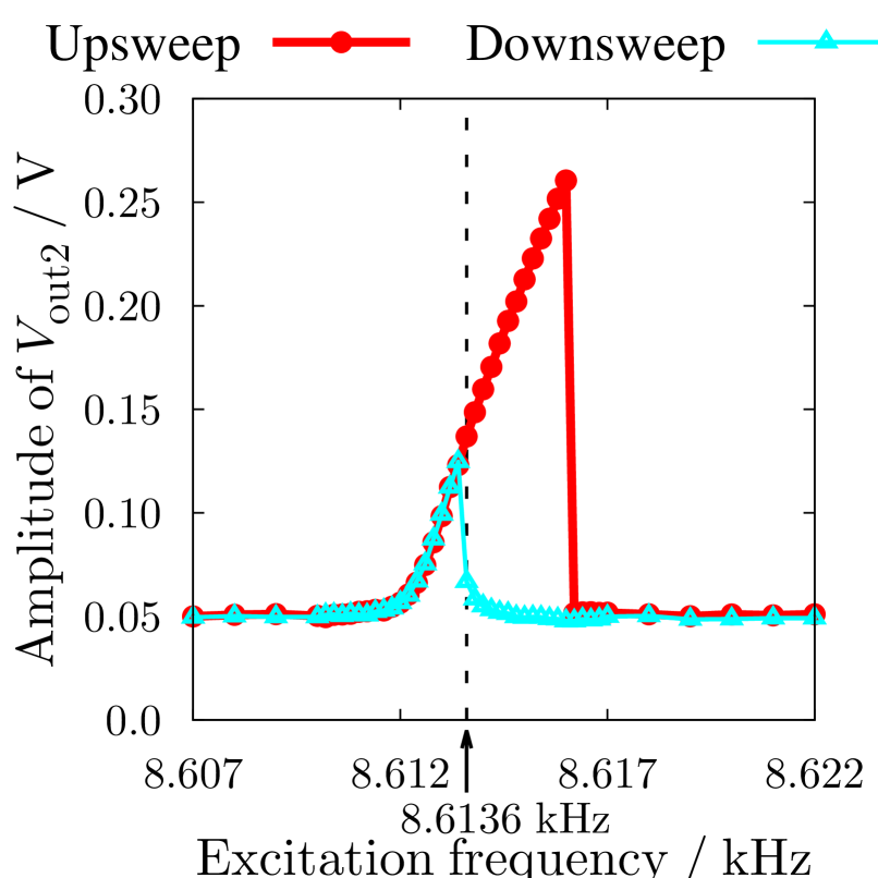
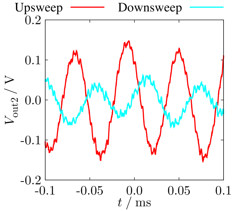
Figure 2(a) (3(a)) shows the experimentally obtained frequency response curves in Res. 1 (Res. 2). The red and aqua lines correspond to the responses at the upsweep and the downsweep of frequency, respectively. The frequency response curves strongly depend on the sweep direction in the hysteresis region. We found that the behavior exhibited by the MEMS resonator qualitatively resemble to each other. Two stable states coexist at kHz kHz in Fig. 2(a) and at kHz kHz in Fig. 3(a). It was considered that the difference of hysteresis is caused by different doping angle, debris deposited during fabrication and die separation, and/or minute cracks [18].
Figures 2(b) and 3(b) show the oscillogram of two stable periodic vibrations at kHz in Res. 1 and at kHz in Res. 2. The red and aqua lines are averaged out over measurements. Below, the excitation frequency is fixed at kHz in Res. 1 and at kHz in Res. 2. The large (small) amplitude vibration is regarded as the “” (“”) state for each resonator. In addition, Res. 1 holds the first bit and Res. 2 the second bit.
3 Switching control method
Figure 4 shows the switching control system. A binary counter is a sequential system that goes through a prescribed sequence of states upon the application of clock signals [17]. In the binary counter, the output transition of one MEMS resonator triggers the switching control of other MEMS resonators. In order to realize a 2-bit binary counter, two MEMS resonators are interconnected in a unidirectional coupled system. Although the electrical noise here appears due to electrical coupling between two MEMS resonators, there does not happen any fault of switching control.
Based on our previous work [11], we construct a switching control system with the feedback control in Res. 1 and apply the control input as a slowly changing dc voltage to the MEMS resonator. The slowly changing dc voltage is given as a square average dc voltage, to which the output voltage is converted by an analog multiplier and a low pass filter of the operational amplifier. In Res. 1, excitation force under control and control input are defined by the following equations:
| (3) | |||||
| (4) |
where denotes the feedback gain, the external reference signal, and the square average dc voltage of Res. 1. The external reference signal is set at () when the state is requested to switch to a large (small) amplitude vibration. Here, () corresponds to the targeted square average dc voltage for the large (small) amplitude vibration. The MEMS resonator exhibits the hysteretic behavior with respect to the excitation force at a fixed excitation frequency [14, 12]. We need to decrease (increase) the amplitude of the excitation force under control when the state is switched to the small (large) amplitude vibration.
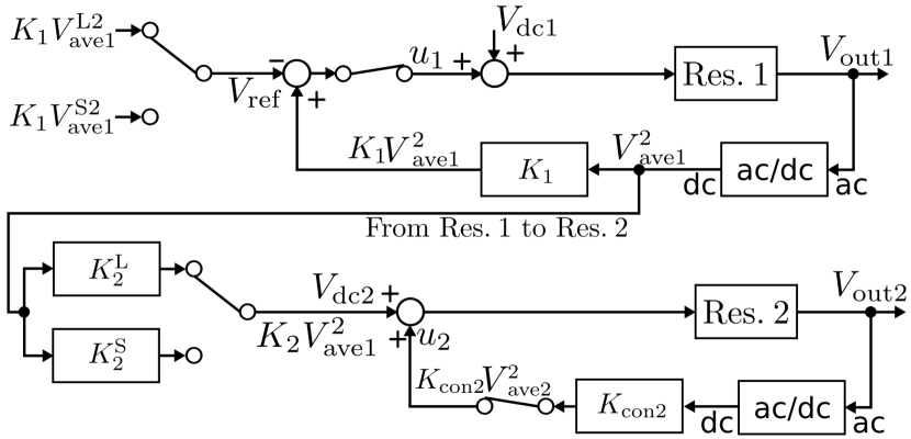
The 2-bit binary counter consists of a series connection of two MEMS resonators, where the output of Res. 1 is connected to the input of Res. 2. As shown in Eq. (3), the excitation force depends on both dc bias voltage and control input . Here, we propose that the dc bias voltage of Res. 2 is given as the input depending on the square average dc voltage of Res. 1. In Res. 2, excitation force under control, dc bias voltage , and control input are obtained by the following equations:
| (5) | |||||
| (6) | |||||
| (7) |
where denotes the gain, the control gain, and the square average dc voltage of Res. 2. When the state of Res. 1 is switched to the large (small) amplitude vibration, the gain is set at (). Here, and are adjusted at V. Furthermore, the feedback gain and the control gain are swept within the operating range and are adjusted at and .
| Clock | Res. 2 | Res. 1 |
|---|---|---|
| 0 | “0” | “0” |
| 1 | “0” | “1” |
| 2 | “1” | “0” |
| 3 | “1” | “1” |
4 Switching control results and discussion
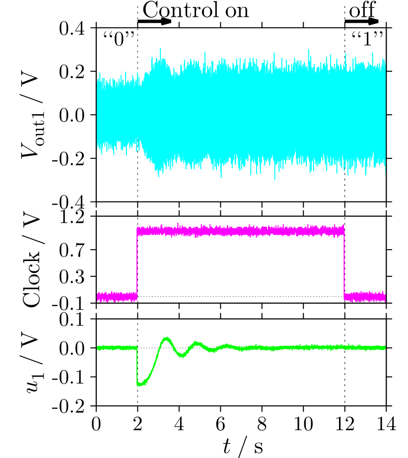
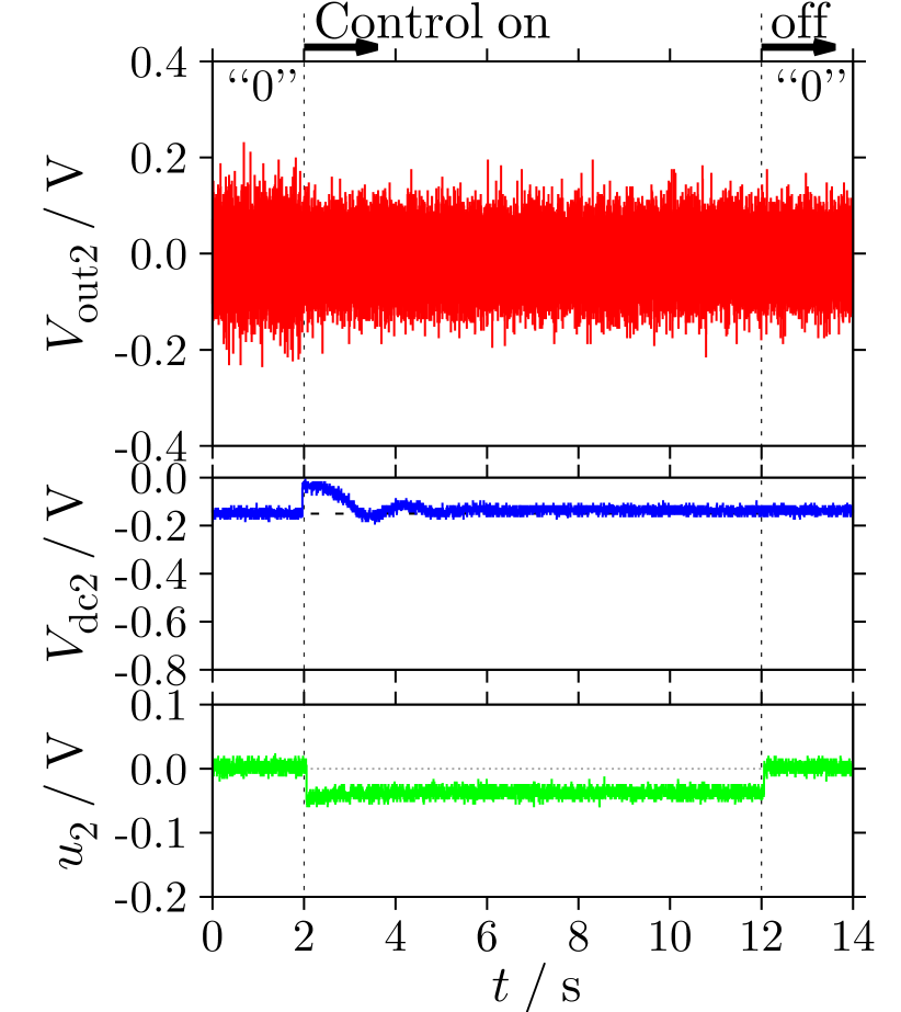
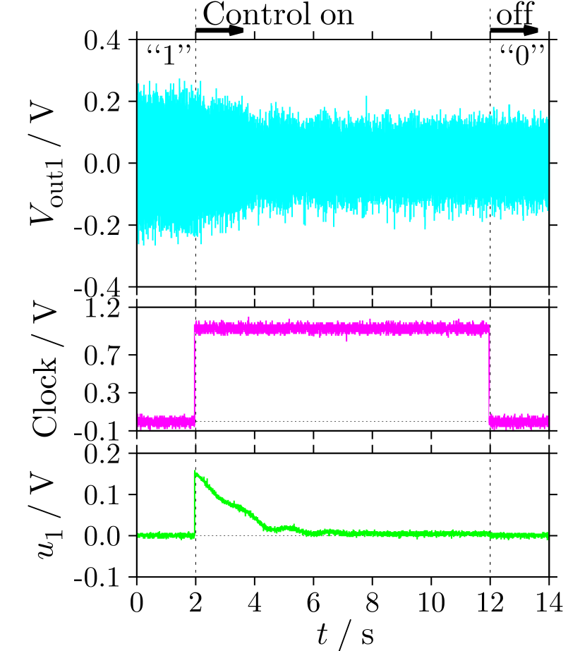
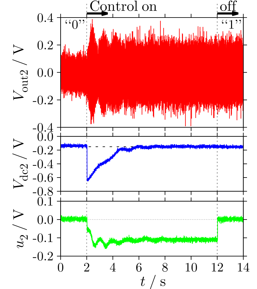
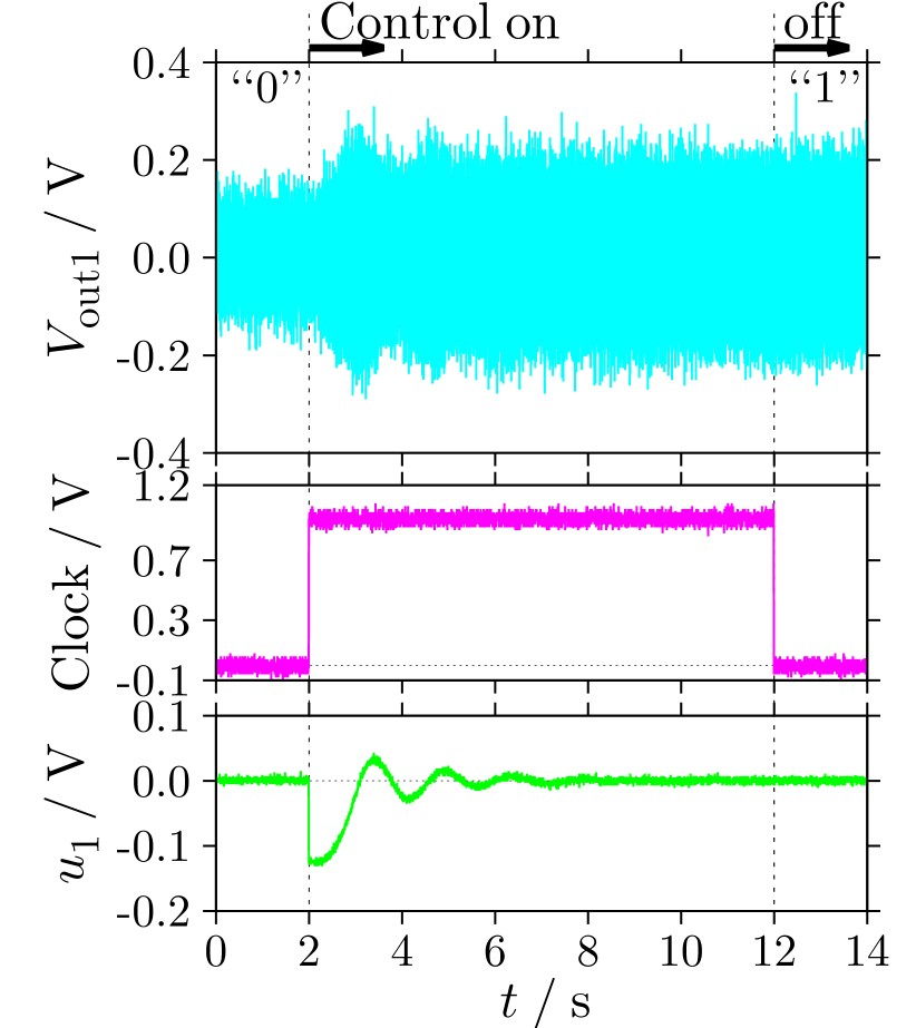
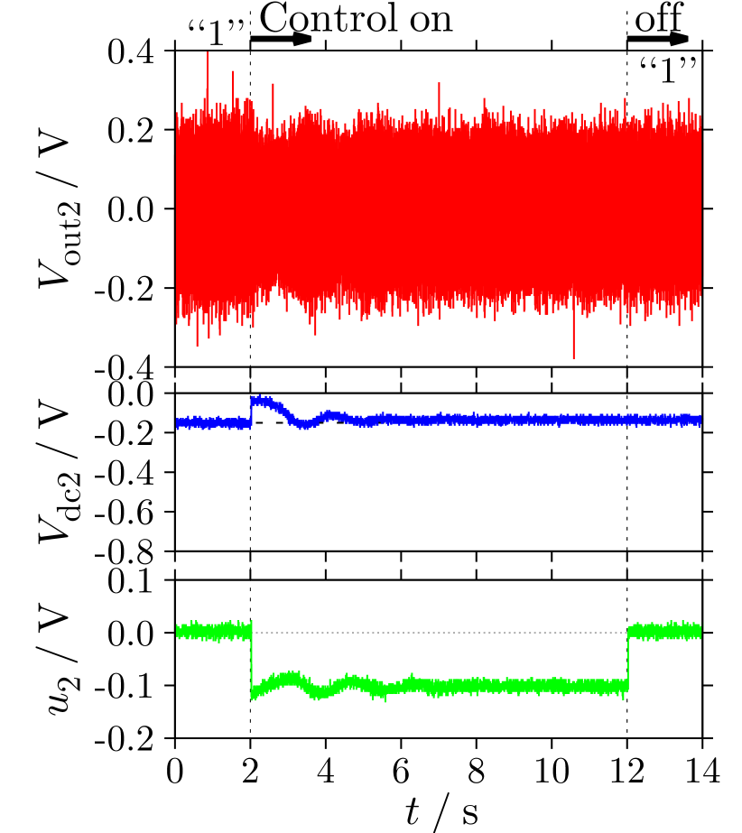
In order to realize the 2-bit binary counter as shown in Tab. 1, we apply the proposed switching control to two MEMS resonators. Fig. 5 shows the experimental results of the switching control. Figs. 5(a), (c), and (e) (Figs. 5(b), (d), and (f)) correspond to the switching control results in Res. 1 (Res. 2). When the clock signal is set at V ( V), the control input is off (on). The external reference signal and the dc bias voltage of Res. 2 are switched by the rising edge of the clock signal.
The switching control from “00” to “01” is implemented as shown in Figs. 5(a) and (b). These results show that Res. 2 stays at “0” and Res. 1 changes from “0” to “1”. Figs. 5(c) and (d) show the switching control from “01” to “10”. When Res. 1 changes from “1” to “0”, it triggers the switching control of Res. 2. Note that the absolute value of the excitation force (the sum of the dc bias voltage and the control input) in Fig. 5(d) exceeds that in Fig. 5(b) when the control input is applied. As a result, Res. 2 changes from “0” to “1”. Figs. 5(e) and (f) show that the present state is “10” and the next state becomes “11”. The transition is slow from “0” to “1” in Res. 1 and Res. 2 stays at “1”. After the switching control was completed, the control input of Res. 1 disappeared due to the feedback control as shown in Figs. 5(a), (c), and (e). It was confirmed that the dc bias voltage of Res. 2 becomes V when the state of Res. 1 converges to a steady state. We found that the switching control results are related to the initial states in two MEMS resonators. Here, when friction and stiction occur in comb-drive resonators, we could not control desired switching behaviors between coexisting stable states as a binary counter.
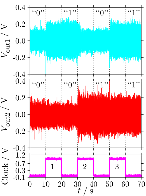
Figure 6 shows the oscillogram of the switching control sequence. The states in two MEMS resonators start from “00” and continues to “01”, “10”, and “11” at each clock signal. Here, the outputs must repeat the binary count sequence with a return to “00”. However, the switching from “11” to “00” is not realized in the proposed switching system.
In order to implement the switching from “11” to “00”, we propose that a reset operation is applied to the coupled MEMS resonators. When the control input is not applied, every initial state converges toward either of two stable states (“0” and “1”) due to two basins of attraction. The small amplitude solution has the basin of attraction around the origin [3, 6]. Based on these preceding results, the reset operation can be realized. As a result, we confirmed that two coupled MEMS resonators can be used as a -bit binary counter by using the proposed switching control and the reset operation.
5 Conclusion
We investigated a binary counter that consists of a coupled system of MEMS resonators with nonlinear characteristics. It was confirmed that the switching control results are related to the initial states in coupled resonators. To the best of our knowledge, we experimentally realized the novel switching control sequence (“00” “01” “10” “11”) as a 2-bit binary counter that consists of coupled nonlinear MEMS resonators. It was also proposed that a reset operation is applied to MEMS resonators for the switching control from “11” to “00”. Since our proposed switching control system is only a prototype, its performance will be improved by an optimized switching control method. Nevertheless, this study is the world’s first implementation of a logic system consisting of electrically coupled nonlinear MEMS resonators. In addition, this paper opens the way for further investigations of the switching control of coexisting states in coupled nonlinear dynamics.
Acknowledgments
This work was supported in part by the Global COE of Kyoto University, Regional Innovation Cluster Program “Kyoto Environmental Nanotechnology Cluster”, and JSPS KAKENHI (Grant-in-Aid for Exploratory Research) 21656074. The authors would like to express our appreciation to Dr. S. Naik (SPAWAR, USA) for fruitful discussions and supports to design MEMS resonators. One of the authors (AY) would like to thank Mr. Y. Tanaka (Department of Electronic Science and Engineering, Kyoto University) for comments through discussions.
References
- [1] R. L. Badzey, G. Zolfagharkhani, A. Gaidarzhy, P. Mohanty, Appl. Phys. Lett. 85 (2004) 3587.
- [2] R. M. C. Mestrom, R. H. B. Fey, J. T. M. van Beek, K. L. Phan, H. Nijmeijer, Sens. Actuators A: Phys. 142 (2008) 306.
- [3] Q. P. Unterreithmeier, T. Faust, J. P. Kotthaus, Phys. Rev. B 81 (2010) 241405.
- [4] S. Naik, T. Hikihara, H. Vu, A. Palacios, V. In, P. Longhini, J. Sound Vib. 331 (2012) 1127.
- [5] D. Antonio, D. H. Zanette, D. López, Nat. Commun. 3 (2012) 806.
- [6] A. Yao, T. Hikihara, Proc. of NOLTA2012 (2012) 352.
- [7] J. A. Pelesko, D. H. Bernstein, Modeling MEMS and NEMS, Chapman & Hall/CRC, 2003, Ch. 5.
- [8] V. Kaajakari, Practical MEMS, Small Gear Publishing, 2009.
- [9] I. Mahboob, H. Yamaguchi, Nature Nanotech. 3 (2008) 275.
- [10] H. Noh, S.-B. Shim, M. Jung, Z. G. Khim, J. Kim, Appl. Phys. Lett. 97 (2010) 033116.
- [11] A. Yao, T. Hikihara, ELEX 9 (2012) 1230.
- [12] A. Uranga, J. Verd, E. Marigó, J. Giner, J. L. Muñóz-Gamarra, N. Barniol, Sens. Actuators A: Phys. 197 (2013) 88.
- [13] S. C. Masmanidis, R. B. Karabalin, I. De Vlaminck, G. Borghs, M. R. Freeman, M. L. Roukes, Science 317 (2007) 780.
- [14] D. N. Guerra, A. R. Bulsara, W. L. Ditto, S. Sinha, K. Murali, P. Mohanty, Nano Lett. 10 (2010) 1168.
- [15] I. Mahboob, E. Flurin, K. Nishiguchi, A. Fujiwara, H. Yamaguchi, Nat. Commun. 2 (2011) 198.
- [16] D. Hatanaka, I. Mahboob, H. Okamoto, K. Onomitsu, H. Yamaguchi, Appl. Phys. Lett. 101 (2012) 063102.
- [17] M. M. Mano, Digital Design, Prentice Hall, 1991, Ch. 6.
- [18] S. Naik, T. Hikihara, ELEX 8 (2011) 291.
- [19] S. Naik, Investigation of synchronization in a ring of coupled MEMS resonators, Ph. D. thesis, Kyoto University, 2011.
- [20] V. Kempe, Inertial MEMS: Principles and Practice, Cambridge University Press, 2011, Ch. 6.