Also at ]Helmholtz-Institut Jena, Helmholtzweg 4, 07743 Jena, Germany
Halo Coupling and Cleaning by a Space Charge Resonance in High Intensity Beams
Abstract
We show that the difference resonance driven by the space charge pseudo-octupole of high-intensity beams not only couples the beam core emittances; it can also lead to emittance exchange in the beam halo, which is of relevance for beam loss in high intensity accelerators. With reference to linear accelerators the “main resonance” (corresponding to the Montague resonance in circular accelerators) may lead to such a coupling and transfer of halo between planes. Coupling of transverse halo into the longitudinal plane - or vice versa - can occur even if the core (rms) emittances are exactly or nearly equal. This halo argument justifies additional caution in linac design including consideration of avoiding an equipartitioned design. At the same time, however, this mechanism may also qualify as active dynamical halo cleaning scheme by coupling a halo from the longitudinal plane into the transverse plane, where local scraping is accessible. We present semi-analytical emittance coupling rates and show that previously developed linac stability charts for the core can be extended - using the longitudinal to transverse halo emittance ratio - to indicate additional regions where halo coupling could be of importance.
I INTRODUCTION
The possibility of manipulating the 6D phase space distribution of particle beams by exchanging emittances between planes can be important for optimum performance as well as for minimizing beam loss. In the context of free electron lasers, for example, emittance exchange between transverse and longitudinal planes has been proposed to take advantage of very small source longitudinal emittances. For this purpose dispersion-based concepts for multi-GeV electron beams involving chicanes, transverse RF cavities as well as quadrupoles have been suggested xiang-chao2011 . For (partially stripped) ion beams the proposal was made recently that a beam with equal transverse emittances can be effectively transformed into a more flat beam matched better to subsequent ring injection, where this rotator includes normal quadrupoles, a stripper, chicane and skew quadrupoles groening2011 .
For circular machines the idea of employing lattice nonlinear resonances to work on beam tails and halo cleaning was proposed some time ago chao1976 . With reference to the CERN Intersecting Storage Ring the suggestion was made to use a 5th order resonance to “pump” protons into the tail up to the aperture or a distant scraper. This would allow to clean the halo dynamically rather than by applying - as usual - a scraper close to the beam core. In a different context coupling between tails was employed experimentally at the CERN Proton Synchrotron, where insufficient (transverse) Landau damping of head-tail modes in one plane could be successfully enhanced by linear coupling with the tail distribution in the other plane plane metral1998 .
In high intensity accelerators any active concept addressing emittance exchange needs to deal with space charge and possible side effects of it. In our study we consider the intrinsic space charge pseudo-octupole - always present in a non-uniform spatial distribution - as driving term of a nonlinear difference resonance and explore its possible role in an active emittance coupling scheme. Core and halo emittance coupling is an important issue for high intensity linacs, where trade-offs between longitudinal acceptance and synchronous phase require careful consideration (see, for example, Ref. fu ).
In linear accelerators this space charge difference resonance is known as “main resonance” with the equivalent resonance condition in linac notation . For a discussion of its theory see Refs. epac2002 ; hofmann2006 ; hofmann2012 ; furthermore Ref. groening2009b for the first experimental observation of the linac main resonance at the GSI UNILAC. For reference we mention that in circular accelerators this mechanism is better known as “Montague resonance” montague with the corresponding difference resonance condition . For a detailed experimental study of the Montague resonance in the CERN Proton Synchrotron see Ref. metral-epac .
In discussions of high intensity linac beams it is often assumed that resonant interaction with a space charge driven nonlinearity primarily affects the beam core. For the latter it is assumed that rms emittance transfer between longitudinal and transverse planes should be avoided. This can be achieved either by using a priori “equipartitioned” beams, or simply by avoiding the corresponding resonance condition and work with non-equipartitioned beams and a higher flexibility of lattice tuning. The latter option has found new interest for H--linacs, where avoiding the risk of intrabeam stripping losses ibs is helped by reduced transverse focusing and removing the constraint of an equipartition requirement.
The main point of this study is to explore whether the emittance coupling concepts describing primarily the beam core can be extended to describe coupling effects in the beam halo - whatever the origin of it may be. Along this line we also examine the possibility of employing space charge and the core-halo coupling in a strategy for active transfer of longitudinal halo into the transverse plane, where it can be scraped in a well-controlled way.
Our study is carried out with the TRACEWIN code in an idealized transport lattice with RF focusing, hence ignoring acceleration and all additional complexity of a specific linac lattice. In Section II we present some details of the ideal model; in Section III results for dynamical crossing of the main resonance with/without halo; in Section IV we present results for fixed tunes; in Section V analytical scalings are summarized; in Section VI we introduce extended stability charts, with concluding remarks in Section VII.
II Lattice, beam core and halo definitions
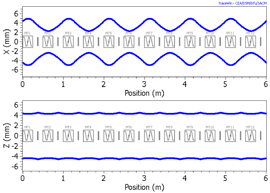
Without lack of generality we employ an “idealized accelerator” lattice with a periodic FODO channel (85 cells, with cell length arbitrarily chosen as 1 m) with linearly varying transverse phase advance and - for simplicity - a single RF kick per cell to generate longitudinal focusing with a fixed phase advance of 740 per cell throughout the paper (Fig. 1 only showing first six cells).
The current is chosen such as to yield a transverse tune depression of about 20%, which is modest for high current linacs. We note that for this kind of space charge physics acceleration can be ignored, because the only parameters that matter are the ratio of phase advances per cell, the tune depression and the ratios of normalized core or halo emittances. Since we always assume that the initial emittances and phase advances in and are equal, we only indicate ratios of and quantities at the start.
We make the following model assumptions: (i) The initial distribution follows the TRACEWIN option of randomly distributed particles in a six-dimensional ellipse (here truncated at 2.8 ); (ii) simulation particles and a 3D Poisson solver (PICNIC); (iii) an “extra halo” distribution is introduced as six-dimensional Gaussian type cut at 2 and - if present - occupied by 2.5% of the total number of particles; (iv) the halo size is expressed by the 99.9% emittance as area of an ellipse defined by using core twiss parameters and containing 99.9% of the particles; (v) we allow for a nonsymmetric (anisotropic) halo with independent emittances transversely and longitudinally. The halo emittances are described by independent multiplication factors with respect to the core emittances. The value of 2.5% halo intensity is relatively arbitrary and higher than what can usually be tolerated in high power linacs. Yet it is still low enough to ensure that the halo space charge force is only a weak contribution, which is the main argument for it in our study.
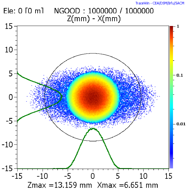
Note that this study assumes initial Gaussian halo profiles throughout and ignores entirely the question of what physical mechanism generates the halo, which might for example be mismatch or errors in linear accelerators. A projection of a characteristic initial core plus halo distribution into the real plane is shown in Fig. 2 for .
III Simulation results for dynamical crossing
In this section we present simulation results under the assumption of a linearly decreasing transverse phase advance such that the is crossed from left to right. We mention that the analogous crossing in the opposite direction yields similar but not equal results. There are some subtle differences, however, which will be discussed further in Section IV.
III.1 Crossing without extra halo
For reference we first review this crossing in the absence of extra halo as shown in Fig. 3 (). The tune footprint with initial rms emittances is plotted on the stability chart in the top of Fig. 3. In this chart for an initial rms emittance ratio the stop-band increases with space charge, which provides the driving term. For a detailed discussion see Section V). The footprint is determined in TRACEWIN as ratio of the and shown in the insert in the upper left corner of Fig. 3; these values are extracted as rms values of tunes obtained from tracking of all particles. A linear tune sweep over 85 cells (here 85 m) and initial tune depression are assumed. The crossing of the center of resonance condition in this case occurs at cell 50. Note that in this and all following graphs the distance on the abscissa in meters is identical with the cell number for our lattice example.
It is noted that the crossing leads to the expected rms emittance transfer, where the final state is nearly “equipartitioned”. The longitudinal rms emittance reduction is about double the increase of each transverse one. This reflects the fact that the longitudinal degree of freedom has to “heat” both transverse - a kind of energy conservation supported by the observation that the sum of all three rms emittances is constant within few percent. The initial values of the 99.9% emittances reflect a small halo due to truncation of the core distribution at 2.8 . They follow the same pattern of exchange as the rms emittances, including an approximate constancy of their sum. For the following discussion it is important to note that the equipartition process itself does not generate additional halo - only exchange.
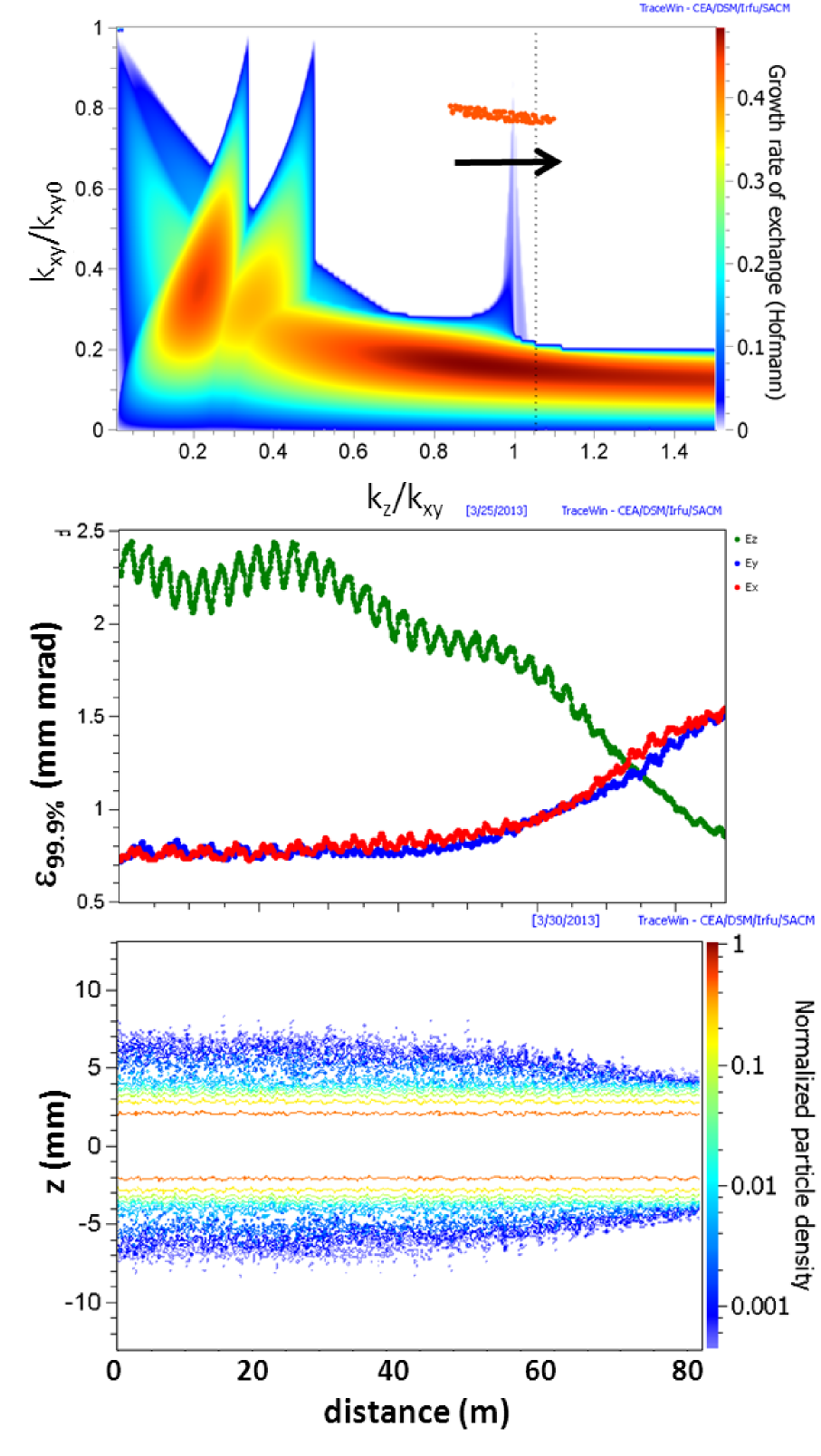
III.2 Extra purely transverse halo
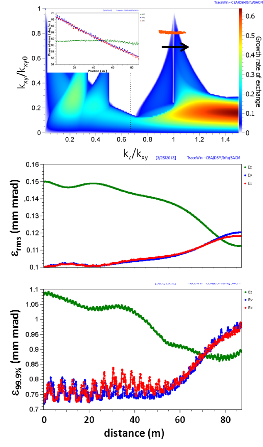
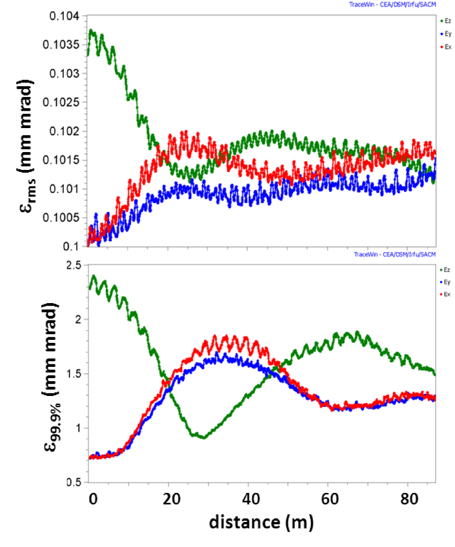
Next we consider the same parameters for the core as before, but now we add a purely transverse halo distribution with multiplication factors , which results in an initial ratio for the 99.9% emittances and inverts the core and halo emittance ratios. The tune ramp is extended to over again the 85 cells. The rms emittances again roughly equipartition. This also applies to the 99.9% emittances, but their transfer occurs into the opposite direction: the two initially larger transverse halo emittances “pump” the longitudinal halo emittance, which more than doubles in a first swing. Thereafter, apparently, a small fraction of halo particles oscillates back and forth between planes - approximately around halo emittance equipartition as shown in Fig. 4.
III.3 Nearly equipartitioned core and purely longitudinal halo
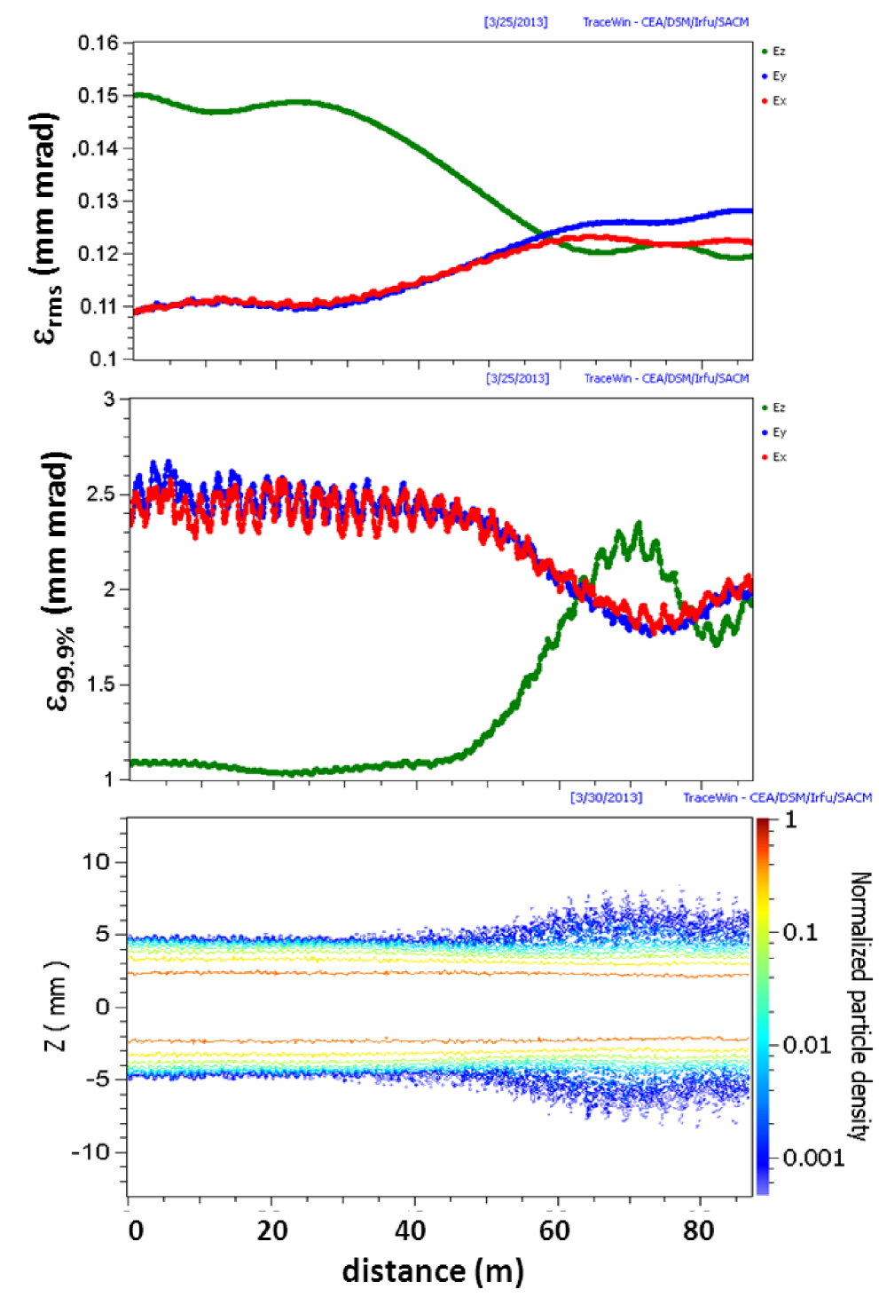
Here we assume an almost equipartitioned core with , which results in a practically negligible stopband width for the main resonance as shown in Fig. 5. We furthermore add a purely longitudinal halo with corresponding factors , which implies a starting ratio for the 99.9% emittances. The transverse tune is ramped from . The coupling has a weak effect on the rms emittances, which merge together as well - partly due to the shrinking longitudinal halo. The 99.5% emittances come to a full exchange with some overshoot and qualitatively the same behavior as the rms and 99.5% emittances in Fig. 3. Hence, the longitudinal halo is almost fully converted into a transverse halo with little effect on the core emittances. Fig. 5 also suggests that the coupling of halo emittances is subject to a much broader stopband than the one shown for the core, which is calculated for the core emittance ratio (see also Section VI.
III.4 Dynamical halo cleaning with transverse scrapers
Here we assume an isotropic halo with . As expected no emittance exchange occurs, as this beam is equipartitioned both in core and halo. We next define a transverse scraper by introducing in three consecutive cells circular apertures at positions, where the beam is round. In our example such a scraper of 4 mm radius sharply eliminates the transverse halo particles (with 3% reduction of beam intensity). Assuming that the scraper is located in the lattice before the coupling resonance is reached, the latter can pump the longitudinal halo into the transverse plane. The location of this scraper is found to be most effective at cells 38/39/40 (equal to distance in m), where . Note that the tune ratio reaches the center of the stopband () after slightly less than 20 additional cells. For our parameters 20 cells is also the characteristic emittance exchange time for a static tune placed right on the stopband, hence without ramping across it. The issue of characteristic emittance exchange time is further discussed in Section IV as it is the basis for choosing the scraper position most effectively.
The result of this simulation is shown in Fig. 6. It is seen that the coupling of the longitudinal halo into the transverse plane makes the transverse 99.9% emittances grow - following again the already observed conservation of the sum of all three emittances. To avoid a partial return into the longitudinal plane, which would bring the 99.9% back to about the value 1.5 in our example, we have added a second scraper with only two apertures in cells 75/76. The second scraper makes sure that the halo cleaning remains conserved for all three planes. The rms emittances are only changing by a few percent as a result of the scraping.
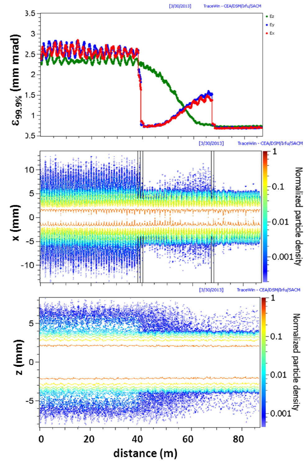
Note that the second scraper is unnecessary, if fine tuning of the tune ramp is realized such that the coupling stopband is left after the longitudinal halo emittance has reached its minimum. This helps reducing the scraped intensity - also in view of the fact that some remaining transverse halo is not an issue of big concern in linacs with large enough transverse aperture. Removing the longitudinal halo this way appears promising as it helps shifting the synchronous phase towards higher acceleration rate.
IV Simulation of static tunes
In this section we study the topology of core and halo coupling at the main resonance stopband for fixed values of (“static tunes”), which reveals some interesting details not resolvable with dynamical crossing. In particular, the validity of different stopband widths for core and halo is clearly seen in cases where their emittance ratios differ.
IV.1 Same emittance ratio in core and halo
Keeping the transverse tunes fixed reveals different features of exchange, depending on the distance from the stopband and at which side. We assume and , which gives the halo the same initial emittance ratio of 3:1. With the corresponding starts at the right edge of the stopband as shown in Fig. 7.
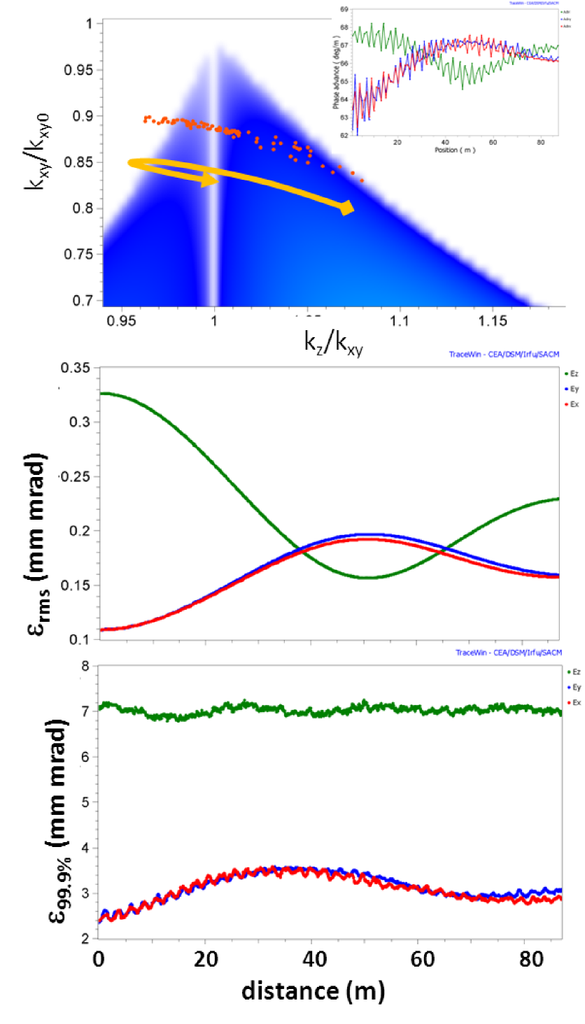
The starting rms emittance exchange leads to a shrinking , which leads to corresponding changes in space charge densities with the effect that also shrinks and moves further left into the stopband; this self-consistent mechanism continues until equality of emittances occurs - with even some overshoot - and reaches the left edge of the stopband and returns back to the center (as indicated by an arrow in the top graph of Fig. 7). The 99.9% emittances, however, show only weak coupling.
A very different behavior is found for , for which is actually outside the right edge of the stopband as shown in Fig. 8.
Not surprisingly, there is practically no rms emittance exchange; however, the halo emittances show effective although not complete coupling. To interpret this phenomenon we note that tunes of halo particles differ from core particle tunes: the tune ratio of very large amplitude halo particles approaches asymptotically the space-charge-free value . On the other hand, the corresponding resonance condition is satisfied close to the r.h.s. edge of the main resonance stopband, which helps understand the dominant halo particle coupling there. In fact, we have not found any effect on halo coupling for a working point at or beyond the l.h.s. edge of the main resonance stopband in Fig. 8.
The asymmetric response on the main resonance stopband is also found in the following: for starting close to the left edge of the stopband the core emittance exchange shifts outside of the stopband and the process stops - in contrast with the behavior at the right edge as in Fig. 7. Note that for an initial longitudinal emittance smaller than the transverse one the side behavior is also reversed.
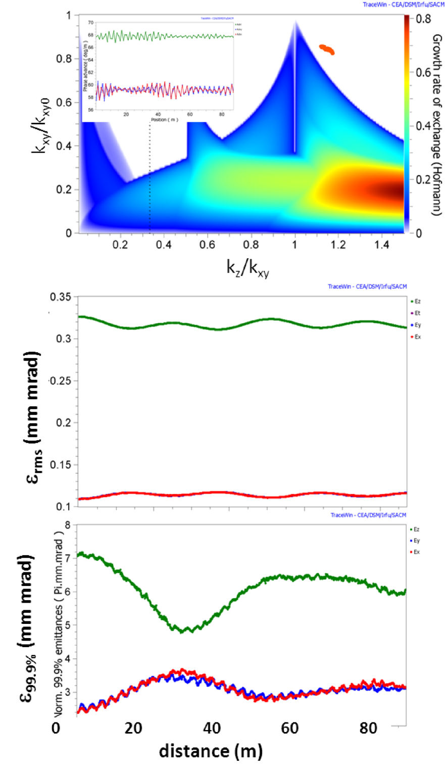
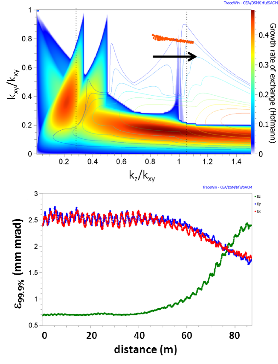
IV.2 Symmetric core with longitudinal halo
Assuming we expect practically no effect on the rms emittances at or near as already found in the crossing case of Fig. 5. A purely longitudinal halo with shows emittance exchange depending on the value of . We find that halo emittance coupling is most effective at the condition (see Fig. 9) and gradually vanishes away from it in either direction. Note that this is supported by the fact that for equal rms emittances the condition coincides with the condition - the asymptotic resonance condition for very large amplitude halo particles - in contrast with the case of unequal emittances in Section IV.1.
By testing different values of we actually find that the region of halo emittance exchange is described quite well by a stability chart generated with the halo emittance ratio (rather than core emittance ratio). This can be explained by the observation that the driving term for both the exchange of core and halo particles is the space charge multipole. This finding will be pursued further in Sections V and VI.
V Semi-analytical scalings
For practical applications it may be useful to consider the approximate scaling expressions for the main resonance stopband width and exchange time, which have been derived in Ref. hofmann2006 . Using and the tune ratio as variable, the stopband width can be written in the form
| (1) |
where it is noted that the longitudinal tune depression is (approximately) related to the transverse one according to
| (2) |
As an example we mention that for and the resulting is in good agreement with Fig. 3.
A corresponding expression for the e-folding time for emittance coupling is suggested in Ref. hofmann2006 for the center of the stop-band. By comparison with simulation results we find that in the region of moderate emittance imbalance the number of cells required to reach the first crossing of emittances is basically independent of the emittance ratio and found as
| (3) |
We also find that the coupling distance estimates in Eq. 3 apply quite well to the halo exchange in spite of the fact that the coupling of halo particles with the core - via its space charge pseudo-octupole - is expected to decrease with increasing distance from the core.
VI Extended stability charts
Our calculations give clear evidence that halo emittance exchange may occur independent of whether a core emittance exchange takes place or not. The conditions for effective halo emittance exchange at the main resonance are: (i) the presence of a space charge octupole as driving term (always given for a non-uniform beam); (ii) fulfilment of the resonance condition and (iii) different emittances, otherwise there is exchange of amplitudes of individual particles without a net global transfer. It is thus appropriate to use distinct stability charts for core and halo, where the rms emittance ratio is used for the core, and the 99.9% (or similar) emittance ratio for the halo. This is demonstrated in Fig. 10 for a crossing of the main resonance from left to right with ; furthermore the assumption of a nearly equipartitioned core () and a purely transverse halo with , which results in a 99.9% emittance ratio . We define an extended stability chart in the following way: the halo stability chart is plotted as contour lines on top of the solid core chart - each one with the corresponding emittance ratio. The 99.9% emittance curve gives clear evidence that this exchange occurs over a broad range of , which we find is comparable with the width of the stopband (halo contours) at the main resonance.
Crossing from right to left with confirms a similar width of response in the variable , which is shown in Fig. 11. Hence in both cases the very narrow main resonance stopband of the core is found irrelevant for the halo.
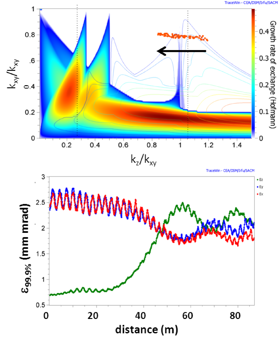
For creating these extended charts we have assumed that the above described behavior at the main resonance is also applicable in an analogous way to all other resonances on the chart.
VII Conclusion
We have shown that the presence of the space charge pseudo-octupole - in all non-uniform beam models - is not only a source of emittance exchange for the core emittances, but also for halo emittances. The strength of this driving term is considerable - only very few betatron periods are needed in a high current linac to reach full exchange of emittances.
These findings allow to extend the interpretation of linac stability charts in order to describe separately possible core and halo emittance exchange. For the main resonance the corresponding width is readily estimated by an approximate expression containing the respective emittance ratio.
For practical linac design there is an incentive to avoid undesirable transfer of halo from the transverse into the longitudinal, which can get lost out of the bucket. This enhances the importance of avoiding this coupling resonance - or even the vicinity of it - in the main part of a linac. We find no argument at this level in support of the frequently made assumption that it is advantageous to make the core equipartitioned. On the contrary, it may be appropriate to relax conditions and enable a non-equipartitoned bunch in the interest of strictly avoiding the resonance and halo coupling. Refraining from enforced equipartitioning may in consequence turn out advantageous for the design.
On the other hand, it is suggested to consider this resonance for an active scheme of longitudinal halo transfer into the transverse direction, where it can be scraped. In practice such use of the resonance should be limited to a transition between linac structures and avoided elsewhere. In any case our study makes it clear that besides halo intensity it is also important to study halo emittances independently for the longitudinal and transverse planes.
References
- (1) D. Xiang and A. Chao, Phys. Rev. ST Accel. Beams 14, 114001 (2011).
- (2) L. Groening, Phys. Rev. ST Accel. Beams 14, 064201 (2011).
- (3) A.W. Chao and M. Month, Nucl. Instr. Methods 133, 405 (1976).
- (4) E. Metral Part. Accel. 62, 259 (1999).
- (5) S. Fu et al., paper MOI1C01, Proc. HB2012, Beijing, China, September 17-21, 2012.
- (6) I. Hofmann, G. Franchetti, J. Qiang, R. Ryne,F. Gerigk, D. Jeon and N. Pichoff in Proceedings of the European Accelerator Conference, Paris, 2002, ed. J.L. Laclare, p. 74 (2002).
- (7) I. Hofmann and G. Franchetti, Phys. Rev. ST Accel. Beams 9, 054202 (2006).
- (8) I. Hofmann, paper TUO3A01, Proc. HB2012, Beijing, China, September 17-21, 2012.
- (9) L. Groening, I. Hofmann, W. Barth, W. Bayer, G. Clemente, L. Dahl, P. Forck, P. Gerhard, M. S. Kaiser, M. Maier, S. Mickat, T. Milosic, and S. Yaramyshev, Phys. Rev. Lett. 103, 224801 (2009).
- (10) B.W. Montague, CERN-Report No. 68-38, CERN, 1968.
- (11) E. Metral et al. Proceedings of the European Accelerator Conference, Lucerne, July 5-9, 2004, p. 1894 (2004).
- (12) A.V. Alexandrov et al., Phys. Rev. Lett. 108, 114801 (2012).