Polariton excitation in epsilon-near-zero slabs: transient trapping of slow light
Abstract
We numerically investigate the propagation of a spatially localized and quasi-monochromatic electromagnetic pulse through a slab with Lorentz dielectric response in the epsilon-near-zero regime, where the real part of the permittivity vanishes at the pulse carrier frequency. We show that the pulse is able to excite a set of virtual polariton modes supported by the slab, the excitation undergoing a generally slow damping due to absorption and radiation leakage. Our numerical and analytical approaches indicate that in its transient dynamics the electromagnetic field displays the very same enhancement of the field component perpendicular to the slab, as in the monochromatic regime. The transient trapping is inherently accompanied by a significantly reduced group velocity ensuing from the small dielectric permittivity, thus providing a novel platform for achieving control and manipulation of slow light.
I Introduction
Physical mechanisms driving to slow and fast light have attracted considerable attention from the scientific community in the last decades Tsakmakidis et al. (2007); Boyd (2009); Kim et al. (2012). The inherent interest in slow light comes from the long matter-radiation interaction time, which can lead to considerable enhancement of all nonlinear processes that in turn may be exploited for active functionalities Vlasov et al. (2005), e.g. all-optical switching and modulation Mingaleev et al. (2006); Bajcsy et al. (2009). The nonlinearity may also be enhanced by reducing the effective area in subwavelength silicon on insulator and plasmonic waveguides Afshar and Monro (2009); Marini et al. (2011), where tight confinement opens up possibilities for miniaturized nonlinear applications Koos et al. (2007); Palomba and Novotny (2008); Kauranen and Zayats (2012). Alternatively, extreme nonlinear dynamics Ciattoni et al. (2010, 2011), enhanced second and third harmonic generation Vincenti et al. (2011); Ciattoni and Spinozzi (2012) is predicted in epsilon-near-zero (ENZ) metamaterials, where the linear susceptibility is tailored in such a way that its modulus becomes comparable with the nonlinear counterpart. Boosting the nonlinearity of ENZ plasmonic channels can also lead to active control of tunneling Powell et al. (2009), switching and bistable response Argyropoulos et al. (2012). ENZ metamaterials have also been used for directive emission Enoch et al. (2002); Alu et al. (2006), cloaking Alu and Engheta (2005), energy squeezing in narrow channels Silveirinha and Engheta (2006) and subwavelength imaging Alu et al. (2007); Castaldi et al. (2012).
In all of the above mentioned mechanisms, the trade-off needed to achieve enhanced active functionalities is paid in terms of increased losses. As a result, the ENZ regime one usually invokes refers to the case where the real part of the susceptibility becomes very small, while its imaginary part remains finite. Indeed, due to the stringent physical requirement of causality, Kramers-Kronig relations impose that dispersion be inherently accompanied by loss and the dielectric susceptibility can not become rigorously null. The residual loss either limits or even prevents giant enhancement of coherent mechanisms, e.g. in second and third harmonic generation setups Vincenti et al. (2011); Ciattoni and Spinozzi (2012). Recently, in the context of surface plasmon polaritons, a method has been proposed to overcome the loss barrier for superlensing applications by loading the effect of loss into the time domain Archambault et al. (2012). In our analytical calculations, we will use a similar approach to study the behavior of an electromagnetic pulse that scatters from a slab having a Lorentz dielectric response. Indeed, by considering non-monochromatic virtual modes with complex frequency Archambault et al. (2009), it is possible to drop off the effect of loss on the temporal dependence of the “mode” itself. In this complex frequency approach, it is possible to achieve the condition where the dielectric susceptibility exactly vanishes. Our formalism treats the dielectric polarization of the medium as a generic Lorentz oscillator that, in the epsilon-equal-to-zero condition, encompasses longitudinal collective oscillations of both electrons (volume plasmons) and ions (longitudinal phonons) that can not be excited by light Ashcroft and Mermin (1976). Recently, the question whether or not volume plasmons can be excited or not by classical light has been revived Henrard et al. (1999); Hoeflich et al. (2009); Henrard et al. (2010); Hoeflich et al. (2010); Muys (2012). Some studies on Mie extinction efficiencies reveal a maximum around the characteristic frequency where the dielectric susceptibility vanishes, attributing the enhanced extinction to the excitation of volume plasmons Hoeflich et al. (2009, 2010). Conversely, other similar studies identify the physical origin of the enhanced extinction in the excitation of leaky modes Henrard et al. (1999, 2010). The latter interpretation is also supported by studies of the excitation of surface phonon polaritons in ENZ slabs Berreman (1963); Ruppin and Englman (1970); Vassant et al. (2012a, b).
In this manuscript we numerically investigate and analytically interpret the scattering of a spatially and temporally localized optical pulse from a dielectric slab in the ENZ regime. We used a finite difference time domain (FDTD) algorithm to solve the full vectorial Maxwell equations coupled to the Lorentz oscillator equation for the dielectric polarization of the slab. We find that, if the carrier frequency of the optical pulse matches the ENZ condition, electromagnetic quasi-trapping occurs within the Lorentz slab since, after the pulse has passed through it, an elecromagnetic-polarization (polariton) oscillation persists and generally slowly damps out. We demonstrate that non-trivial ENZ features like the enhancement of the longitudinal electric field component are still observable in the time-domain. We also find that the above mentioned phenomenology is not observed for optical pulses with carrier frequencies far from the ENZ condition. Thus, in order to grasp the underpinning physical mechanisms responsible for transient trapping in the ENZ regime, we analytically investigate the scattering features of the Lorentz slab by studying the virtual leaky modes of the structure. We recognize that a set of polariton modes with reduced transverse group velocity (, where is the speed of light in vacuum) is excited. Indeed, the plasma frequency plays the role of a cut-off frequency and polaritons in the ENZ regime are intrinsically characterized by a reduced group velocity. Thus, we are able to interpret the transient trapping by means of the excitation of slow polariton modes that are damped off due to medium absorption and radiation leakage in the outer medium.
The paper is organized as follows. In Sec.II we report the results of numerical finite difference time domain (FDTD) simulations, comparing the distinct phenomenologies occuring in ENZ and standard dielectric regimes. In Sec.III we analytical investigate the virtual leaky modes of the structure, we address their properties and we discuss their role in the interpretation of numerical results are developed in section III. In Sec.IV we draw our conclusions.
II Finite Difference Time Domain analysis of the time-domain ENZ regime
II.1 Pulse scattering by a Lorentz slab
Let us consider the scattering interaction sketched in Fig.1(a), where an electromagnetic pulse is launched along the -axis in vacuum and orthogonally impinges on the surface of a dielectric slab. The pulse is a Transverse Magnetic (TM) excitation, with electric , and magnetic field components. The initial profile profile of the transverse electric component is
| (1) |
This field is spatially confined both along the - and - axis, and being its transverse and longitudinal widths, respectively, it is centered at the point and it is longitudinally modulated with period . Hereafter we will focus on very long pulses such that . Thus, the quasi-monochromatic condition is satisfied, where is the pulse central frequency and is the spectral width.
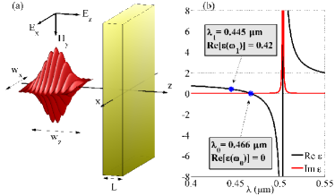
The dielectric slab has width , it is centered at and we assume that, in the presence of the external electric field , the dynamics of its dielectric polarization is governed by the Lorentz oscillator model
| (2) |
where is the resonant angular frequency, is the damping constant, is the oscillator strength and is the dielectric permittivity of vacuum. It is well known that Eq.(2) leads, in the frequency domain, to the constitutive relation where is the Fourier transform of , is the displacement field vector and is the frequency dependent medium dielectric permittivity. The realistic model of Eq.(2) is particularly accurate for describing the medium dielectric response to fields with frequencies close to the resonant frequency (so that contributions due to other resonances can be neglected). Therefore, the Lorentz model is particularly suitable for our analysis since we are here concerned with quasi-monochromatic pulses whose carrier frequency coincides with (or is close to) the frequency
| (3) |
where the real part of the permittivity vanishes, i.e. , the so called epsilon-near-zero (ENZ) regime.
We have performed the numerical analysis of the pulse-slab collision by means of a Finite Difference Time Domain (FDTD) scheme where the polarization dynamics of Eq.(2) are coupled to Maxwell equations for the TM field. Specifically, in order to isolate the relevant phenomenology characterizing the ENZ regime we have analyzed through FDTD simulations two different situations where the same dielectric slab is hit by two spatially equal pulses with different carrier frequencies : the first (pulse ) is such that so that it is suitable to scan the slab behavior in its ENZ regime; the second (pulse ) has for which so that it experiences standard dielectric behavior.
In view of the generality and ubiquity of the Lorentz model of Eq.(2), we have chosen for our numerical simulations a realistic medium with Lorentz parameters , and in order to deal with optical pulses in the visible spectrum, the resonant frequency corresponding to the wavelength . For such parameters Eq.(3) yields and we have set (for which ), the two frequencies corresponding to the wavelengths and respectively. In Fig.1(b) we plot the real and imaginary parts of the dielectric permittivity for the chosen Lorentz parameters as functions of the wavelength , indicating the carrier wavelengths and that characterize the two pulses. We have chosen a slab width to minimize the pulse propagation features and to effectively highlight the impact of the medium polarization on field dynamics. We set , so that the pulse peak reaches the slab after it has been launched. Pulse widths are chosen so that and : the former is comparable with the central wavelength of the pulse in order to provide the optical beam with a non negligible longitudinal field component (see below) whereas the latter corresponds to a temporal width and a spectral width so that the pulses are in the quasi-monochromatic regime.
II.2 Pulse scattering
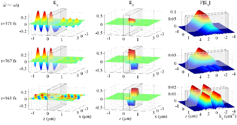
In Fig.2 we report the main results of the FDTD simulation dealing with the interaction of the pulse with carrier frequency with the Lorentz slab represented in the figure by the semitransparent rectangular blocks. The first two columns of the figure contain the plots of , as functions of whereas the third contains the Fourier transform as a function of ; each row of the figure corresponds to a selected simulation time step. At the first time step (first row of Fig.(2)), , the pulse is fully interacting with the slab (the pulse peak being about to hit the slab at ) and the electromagnetic field is characterized by standard reflection/transmission features; in particular both the reflected and transmitted pulses have a transverse bell-shaped spatial profile and accordingly the Fourier transform is peaked as well. Note however that, even in this early transient stage of the interaction, within the slab the longitudinal component is comparable with and much greater than its vacuum counterpart. Such an enhancement of the electric field component perpendicular to the slab is a feature typically associated with monochromatic ENZ regime, arising as a consequence of the continuity of the displacement field component perpendicular to the interface Vincenti et al. (2011); Ciattoni and Spinozzi (2012). Therefore this is the first evidence that the ENZ regime can effectively be observed in thoroughly realistic Lorentz slabs by means of an equally realistic scattering interaction configuration. The second row of Fig.2 corresponds to the time step a time when the incoming pulse (if freely propagating) would have passed behind the slab (its temporal width being ). Note that the longitudinal component is even greater than the previous time step, testimony to the fact that the ENZ regime also occurs in the time-domain. The transverse component shows novel spatial features, even more evidently displayed by its Fourier transform which is no longer bell-shaped and characterized by a complex multi-structured profile. The third row of Fig.2 considers a later time step much longer than the time spent by the pulse to fully travel into the slab and leave it. At this time step, the longitudinal component is still very large within the slab and the transverse component displays novel and unexpected features: it is symmetric under the reflection , it is not transversally bell-shaped and its Fourier transform displays two peaks at the sides of . Such phenomenology can be interpreted only by assuming that the interaction of pulse with the slab is accompanied by the excitation of a polariton mode whose oscillation lasts a time much longer than the pulse-slab interaction time.
II.3 Pulse scattering
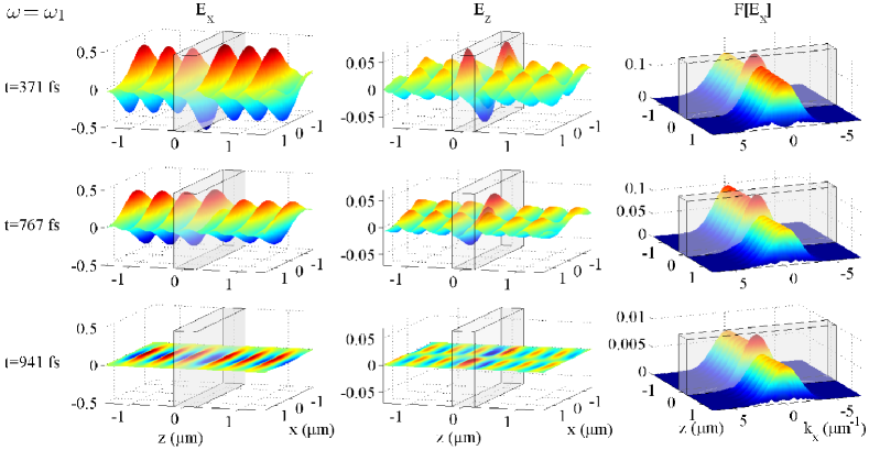
In order to appreciate the novelty of the above discussed time-domain ENZ phenomenology, we now discuss the interaction of pulse with the slab, its carrier frequency being associated to standard slab dielectric behavior. In Fig.3 we report the results of the FDTD simulation relative to pulse and, for comparison purposes, we have given Fig.3 the same structure as Fig.2 with the same fields at same time steps. Remarkably, both and are everywhere and always bell-shaped, while the magnitude of within the slab is comparable with its vacuum magnitude. At the last time step the slab hosts no residual polariton oscillation resulting from the pulse passage. This is precisely the standard expected phenomenology of the reflection and transmission of the pulse by a dielectric slab, and the comparison with the results of Fig.2 proves that the phenomenology it contains is a manifestation of the time-domain ENZ regime
II.4 Transient trapping in the time-domain epsilon near zero regime
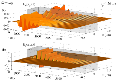
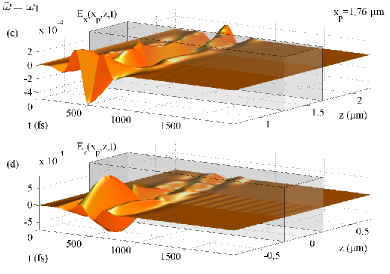
In addition to the remarkable fact that the same features of the monochromatic ENZ regime characterize its time domain counterpart (e.g. the slab hosts a pronounced enhancement of the field ), the results discussed in the previous sections also clearly reveal that the scattering situation leads to the unique excitation of a polariton mode. In order to show more explicitly such a phenomenology, in Fig.4 we have plotted the fields and , for both pulse and pulse as functions of at a fixed plane . The evident feature that emerges is that pulse (see subplots (a) and (b) of Fig.4) produces a strong and damped electromagnetic self-oscillation persisting a time (about ) much longer than the probing pulse duration (), self-oscillation which is conversely not produced by pulse (see subplots (c) and (d) of Fig.4), whose electromagnetic track fades within the slab just after it has left the medium (at about ). We conclude that, in the ENZ regime, the pulse travelling through the slab triggers a novel mechanism of transient light trapping.
III Theoretical analysis of time-domain ENZ regime
III.1 Polariton virtual modes analysis
From the above discussed phenomenology, it is evident that a quasi-monochromatic pulse with a spectrum centered at the zero of the real part of the slab permittivity excites a polariton mode that lasts a time much longer than the pulse-slab interaction time. In order to rigorously prove this statement and gain deeper understanding of the underpinning physical mechanisms that support the time-domain ENZ regime, in this section we analyze the exact quasi-steady modes (virtual modes) of the slab. In our analysis we fully take into account damping processes, which include medium absorbtion and radiation leakage in vacuum, adopting the complex frequency approach Archambault et al. (2009). We start our analysis from the curl Maxwell equations for TM fields
| (4) | |||||
where the polarization satisfies Eq.(2) within the slab () and it vanishes outside the slab (). We take the Ansatz for every field component (, and ), where is the (real) transverse wavevector and is the complex angular frequency with so that only damping modes are considered. Owing to the mutual temporal evolution of the electromagnetic field and of the polarization field , the Ansatz effectively amounts to considering polariton virtual modes. The magnetic field can be expressed in terms of the electric field components so that Maxwell’s equations reduce to
| (5) | |||
| (6) |
where ( being the Heaviside step function) is the -dependent dielectric profile. It is worth stressing that the permittivity is evaluated at the complex frequency . The general solution of Eqs.(5,6) is explicitly given by
| (10) | |||||
| (15) |
where , , is the arbitrary mode amplitude, is a parameter that distinguishes the symmetry of the solutions and is another parameter selecting the sign of the exponentials in vacuum. By construction, the modal fields in Eqs.(10) already satisfy the continuity of the field component parallel to the slab surface () at the interfaces . The boundary conditions (BCs) for the continuity of the displacement field component ()perpendicular to the interfaces yield the dispersion relation
| (16) |
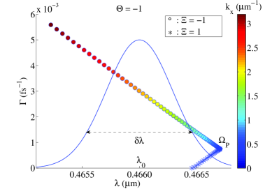
which provides the complex frequency for every given slab thickness and transverse wave vector . We have solved Eq.(16) numerically and obtained the allowed corresponding to different values of using the same slab thickness and Lorentz dispersive parameters of the slab considered in Section II. In Fig.5 we plot the results for the case in the complex plane parametrized through the wavelength and the damping constant (i.e. ), using circles and stars for the and modes, respectively, and using the marker color to label the value of the corresponding . Note that the and modes belongs to two different branches which are characterized by the fact that the modes have damping constant greater than the modes. This property can be easily understood by considering the -component of the non-oscillatory part of the Poynting vector for :
| (17) |
For , the energy outflows from the slab and the damping of the virtual mode is more rapid since it loses energy through both medium absorption and radiation leakage. Conversely, for the electromagnetic energy is dragged into the slab, thus partially compensating for the medium absorption and consequently decreasing the virtual mode damping time (note that there is also a point where on the branch corresponding to the exact balance between medium absorption and radiation drag).
It is remarkable that the and branches intersect each other at point for . In this limit the dispersion relation of Eq.(16) (for ) reduces to
| (18) |
and is satisfied only if . Starting from the Lorentz model, it is straightforward to prove that the permittivity vanishes at that, for the above used Lorentz dispersive parameters, yields and , precisely matching the point of Fig.5 where the two branches intersect each other. In turn, the plasmonic at which the permittivity vanishes plays a central role in the analysis of the virtual modes. For the complex frequencies reported in Fig.5, and therefore, all the obtained modes with symmetry imply the time-domain ENZ regime.
In the same portion of the complex plane we have numerically found no allowed modes for the symmetry . This can be grasped by expanding both sides of Eq.(16) in Taylor series of (since ); at the zeroth order we readily obtain which is not consistent if (and which, on the other hand, yields for ).
III.2 Interpretation of FDTD results in terms of virtual polariton modes and slow-light regime
Usually, within the standard real frequency approach, the solutions for the slab modes with are disregarded since they are considered unphysical. Indeed, if , the solutions with represent confined modes propagating along the -direction, while solutions with are unbound modes that diverge at . In addition, the introduction of the complex frequency introduces an inherent field singularity in the far past . Due to such intrinsic singularities, it is strictly impossible to rigorously excite a single virtual mode, its global existence on the whole space-time being unphysical. However, both singularities occur asymptotically and therefore virtual modes provide a very adequate description of the transient ENZ slab behavior occurring within a spatially bounded region and through a finite time lapse. In order to prove this statement and to basically provide a theoretical analytical description of the transient light trapping discussed in Sec.2D, in Fig.5 we have superimposed the temporal spectrum profile of the incoming pulse of Eq.(1) (using the thin continuous line) on the complex-plane virtual modal structure. Note that, due to its wavelength bandwidth , the pulse spectrum centered at overlaps a limited portion of the considered complex frequency plane so that, specifically, the sole virtual modes with are actually excited by the considered pulse 0. From Fig.5 it is evident that the excited virtual modes are characterized by the transverse wavevector spanning the range and that, due to the finite bandwidth of the impinging pulse, the excited virtual modes with largest amplitude are those around the central transverse wavevector , which corresponds to close to . This observation is in striking agreement with the results contained in Fig.2, where one can see that the transverse Fourier transform of the field has, at the latest time step, two peaks centered at and whose width is of the order of . Therefore, when the pulse 0 impinges onto the slab, it excites precisely the virtual modes analytically predicted in Sec.IIIA, which are compatible with its spectral structure. As a further validation of this statement, note that the virtual modes excited by the pulse 0 () have a damping constant spanning the range (see Fig.5), which corresponds to the extinction time spanning the range . Also this prediction based on the above virtual mode analysis is in striking agreement with the FDTD results since, by looking at panels (a) and (b) of Fig.4, one can see that the electromagnetic excitation persists for a time of the order of , which is compatible with the maximum extinction time of the excited virtual modes. In addition, the spatial symmetry of the virtual polariton modes matches the numerical results displayed in Fig.4: the transverse field component () is antisymmetric with respect to the axis, whereas the longitudinal field component () is symmetric.
The final ingredient needed to thoroughly interpret the transient light trapping observed in FDTD simulations is related to the intrinsic slow-light nature of the phenomenon, which may be preliminarily grasped by considering a bulk Lorentz medium, where transverse plane waves satisfy the dispersion relation . Neglecting medium absorption (), one finds that the phase velocity is and the group velocity is
| (19) |
Thus, in the ENZ regime the phase velocity diverges whereas the group velocity tends to zero . Even though the subwavelength Lorentz slab used in our FDTD simulations is not a bulk medium and absorption has not been neglected, the rough argument above still predicts the correct outcome. Indeed, by numerically solving the dispersion relation of Eq.(16) without neglecting losses one finds that, at the optical wavelength , the transverse phase velocity of virtual polariton modes is superluminal , while the transverse group velocity is extremely reduced . For this reason, it is now clear how the virtual polariton modes, once excited, do not disperse quickly in the -direction and remain quasi-trapped within the slab owing to the tremendously reduced temporal dynamics. We conclude that the above described transient light trapping can be fully interpreted and physically understood by means of slow polariton modes supported by the slab.
III.3 Volume plasmons
Although the above discussed numerical and analytical analysis of the transient light trapping characterizing the time-domain ENZ regime is quite exhaustive, we now discuss its connection with the purely longitudinal modes, either volume plasmons (collective oscillations of electrons) or volume phonons (collective oscillations of ions), which the Lorentz medium can support. Hereafter we focus on volume plasmons, considering an unbounded bulk Lorentz medium where the TM electromagnetic and polarization dynamics are described by Eqs.(2,III.1). For the plane-wave Ansatz , where , , , are the (real) wavevector components and is the generally complex frequency one gets
| (20) | |||
where is the dielectric permittivity with complex frequency . Volume plasmons are purely longitudinal electric oscillations owing to to the collective motion of electrons and are not accompanied by the generation of magnetic field, a feature that for plane waves amounts to the collinearity of the wave vector and the electric field . Therefore, imposing the condition , i.e. , Eqs.(III.3) readily yield and . Thus, volume plasmons are inherently involved in the time-domain ENZ regime we are considering in this paper. However, it is worth noting that the virtual modes of the Lorentz slab are polaritons, entities fundamentally different from volume plasmons (or volume phonons). Indeed, a volume plasmon is strictly characterized by the condition that implies the severe dispersion and, in the presence of the slab boundaries at , inevitably leads to the inconsistency within the slab unless in the outer medium. This is consistent with the well-known impossibility to excite volume plasmons by means of light. On the other hand, from Eq.(10) one can see that the virtual polariton mode component neither vanishes outside the slab nor diverges within it. This is because for polaritons the dispersion relation of Eq.(16) is not as stiff as the volume plasmon dispersion and is satisfied also for . In addition the volume plasmon is a purely electric oscillation with strictly null magnetic field, whereas the considered virtual polariton modes are accompanied by a magnetic field. In turn, even though TM polariton modes and volume plasmons occur in the same spectral region and are accidentally connected by the fact that in the limit the Lorentz slab is almost equivalent to a bulk medium, conceptually they are very distinct entities. In view of this, we conclude remarking that volume plasmons can not be excited by classical light and that the absorption peak observed in experiments Hoeflich et al. (2009, 2010) is due to the excitation of virtual polariton modes, confirming the results given in Refs. Henrard et al. (1999, 2010).
IV Conclusions
In conclusion we have investigated both numerically and analytically the properties of the time-domain ENZ regime. Specifically we have considered a dielectric slab whose polarization dynamics has been described through the realistic and ubiquitous Lorentz model and we have analyzed its interaction with quasi-monochromatic and spatially confined pulses with carrier frequencies close to the crossing point of the permittivity real part. The FDTD analysis has shown that the pulse is able to excite a polarization-electromagnetic (polariton) oscillation which is damped and persists for a time generally longer than the effective time required by the pulse for passing through the slab. The underlying nature of this excitation has been elucidated through the analysis of the slab virtual modes that turn out to be located in a portion of the complex frequency plane close to the plasmonic frequency characterizing plasmon/phonons longitudinal volume excitations. Remarkably, due to this spectral property, both the group velocity and the transverse velocity (parallel to the slab) of each virtual mode turn out to be very small and therefore, the time-domain ENZ regime be naturally regarded as a novel platform for discussing and investigating a plethora of slow-light phenomena.
References
- Tsakmakidis et al. (2007) K. L. Tsakmakidis, A. D. Boardman, and O. Hess, Nature Letters 450, 397 (2007).
- Boyd (2009) R. W. Boyd, Journal of Modern Optics 56, 1908 (2009).
- Kim et al. (2012) K. H. Kim, A. Husakou, and J. Herrmann, Optics Express 20, 25790 (2012).
- Vlasov et al. (2005) Y. A. Vlasov, M. O’Boyle, H. F. Hamann, and S. J. McNab, Nature 438, 65 (2005).
- Mingaleev et al. (2006) S. F. Mingaleev, A. E. Miroshnichenko, Y. S. Kivshar, and K. Busch, Physical Review E 74, 046603 (2006).
- Bajcsy et al. (2009) M. Bajcsy, S. Hofferberth, V. Balic, T. Peyronel, M. Hafezi, A. S. Zibrov, V. Vuletic, and M. D. Lukin, Physical Review Letters 102, 203902 (2009).
- Afshar and Monro (2009) S. V. Afshar and T. M. Monro, Optics Express 17, 2298 (2009).
- Marini et al. (2011) A. Marini, R. Hartley, A. V. Gorbach, and D. V. Skryabin, Physical Review A 84, 063839 (2011).
- Koos et al. (2007) C. Koos, L. Jacome, C. Poulton, J. Leuthold, and W. Freude, Optics Express 15, 5976 (2007).
- Palomba and Novotny (2008) S. Palomba and L. Novotny, Physical Review Letters 101, 056802 (2008).
- Kauranen and Zayats (2012) M. Kauranen and A. V. Zayats, Nature Photonics 6, 737 (2012).
- Ciattoni et al. (2010) A. Ciattoni, C. Rizza, and E. Palange, Physical Review A 81, 043839 (2010).
- Ciattoni et al. (2011) A. Ciattoni, C. Rizza, and E. Palange, Physical Review A 83, 043813 (2011).
- Vincenti et al. (2011) M. A. Vincenti, D. DeCeglia, A. Ciattoni, and M. Scalora, Physical Review A 84, 063826 (2011).
- Ciattoni and Spinozzi (2012) A. Ciattoni and E. Spinozzi, Physical Review A 85, 043806 (2012).
- Powell et al. (2009) D. A. Powell, A. Alu, B. Edwards, A. Vakil, Y. S. Kivshar, and N. Engheta, Physical Review B 79, 245135 (2009).
- Argyropoulos et al. (2012) C. Argyropoulos, P.-Y. Chen, G. D Aguanno, N. Engheta, and A. Alu, Physical Review B 85, 045129 (2012).
- Enoch et al. (2002) S. Enoch, G. Tayeb, P. Sabouroux, N. Guerin, and P. Vincent, Physical Review Letters 89, 213902 (2002).
- Alu et al. (2006) A. Alu, F. Bilotti, N. Engheta, and L. Vegni, IEEE Trans. Antennas Propag. 54, 1632 (2006).
- Alu and Engheta (2005) A. Alu and N. Engheta, Physical Review E 72, 016623 (2005).
- Silveirinha and Engheta (2006) M. Silveirinha and N. Engheta, Physical Review Letters 97, 157403 (2006).
- Alu et al. (2007) A. Alu, M. G. Silveirinha, A. Salandrino, and N. Engheta, Physical Review B 75, 155410 (2007).
- Castaldi et al. (2012) G. Castaldi, S. Savoia, V. Galdi, A. Alu, and N. Engheta, Physical Review B 86, 115123 (2012).
- Archambault et al. (2012) A. Archambault, M. Besbes, and J.-J. Greffet, Physical Review Letters 109, 097405 (2012).
- Archambault et al. (2009) A. Archambault, T. V. Teperik, F. Marquier, and J. J. Greffet, Physical Review B 79, 195414 (2009).
- Ashcroft and Mermin (1976) N. Ashcroft and N. Mermin, Solid State Physics (Harcourt College Publishers, 1976).
- Henrard et al. (1999) L. Henrard, O. Stephan, and C. Colliex, Synthetic Metals 103, 2502 (1999).
- Hoeflich et al. (2009) K. Hoeflich, U. Goesele, and S. Christiansen, Physical Review Letters 103, 087404 (2009).
- Henrard et al. (2010) L. Henrard, C. VanDenBem, P. Lambin, and A. Lucas, Physical Review Letters 104, 149701 (2010).
- Hoeflich et al. (2010) K. Hoeflich, U. Goesele, and S. Christiansen, Physical Review Letters 104, 149702 (2010).
- Muys (2012) P. Muys, Optics Letters 37, 4928 (2012).
- Berreman (1963) D. W. Berreman, Physical Review 130, 2193 (1963).
- Ruppin and Englman (1970) R. Ruppin and R. Englman, Rep. Prog. Phys. 33, 149 (1970).
- Vassant et al. (2012a) S. Vassant, J.-P. Hugonin, F. Marquier, and J.-J. Greffet, Optics Express 20, 23971 (2012a).
- Vassant et al. (2012b) S. Vassant, A. Archambault, F. Marquier, F. Pardo, U. Gennser, A. Cavanna, J. L. Pelouard, and J. J. Greffet, Physical Review Letters 109, 237401 (2012b).