Proposal for realizing a multiqubit tunable phase gate of one qubit
simultaneously controlling target qubits using cavity QED
Chui-Ping Yang1,2, Qi-Ping Su1, and Jin-Ming Liu21Department of Physics, Hangzhou Normal University,
Hangzhou, Zhejiang 310036, China
2State Key Laboratory of Precision Spectroscopy,
Department of Physics, East China Normal University, Shanghai
200062, China
Abstract
We propose a way to realize a multiqubit tunable phase gate of one
qubit simultaneously controlling target qubits with atoms in
cavity QED. In this proposal, classical pulses interact with atoms
outside a cavity only, thus the experimental challenge of
applying a pulse to an intra-cavity single atom without affecting
other atoms in the same cavity is avoided. Because of employing a
first-order large detuning, the gate can be performed fast when
compared with the use of a second-order large detuning.
Furthermore, the gate operation time is independent of the number
of qubits. This proposal is quite general, which can be applied
to various superconducting qubits coupled to a resonator, NV centers
coupled to a microsphere cavity or quantum dots in cavity QED.
pacs:
03.67.Lx, 42.50.Dv
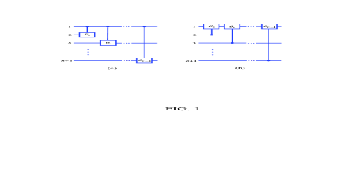
Figure 1: (Color online) (a) Schematic circuit of a multiqubit controlled-phase
(CP) gate with qubit 1 (on top) simultaneously controlling
target qubits (). (b) The circuit for a phase gate with many control
qubits () acting on one target (qubit 1).
Introduction.—Over the past decade, many proposals have been
presented for realizing a multiqubit controlled-phase (CP) or controlled-NOT
gate with multiple-control qubits acting on one target
qubit, using various physical systems [1-7]. These proposals are important
because they opened new avenues for realizing this type of multiquibit
controlled gates, which are of significance in quantum information
processing (QIP).
In this work we focus on a multiqubit tunable phase gate of one qubit
simultaneously controlling target qubits. This gate is useful in QIP
(e.g., it has an important application in quantum Fourier transforms). In
the following, we will present a way for implementing this gate with atoms
in cavity QED.
The proposal has these features: (i) The atoms interact with classical
pulses outside the cavity, thus the experimental challenge of
applying a pulse to an intra-cavity single atom without affecting (many)
other atoms in the same cavity is avoided; (ii) The gate operation employs a
first-order large detuning, thus the gate can be performed fast when
compared with the use of a second-order large detuning; and (iii) The
operation time is independent of the number of qubits and thus does not
increase with the number of qubits.
Multiqubit tunable phase gate.—The multiqubit phase gate here
consists of two-qubit CP gates as depicted in Fig. 1(a). Each two-qubit
CP gate has a shared control qubit (qubit ) but a different
target qubit ( or ). This multiqubit phase gate has the
property: (i) when the control qubit is in the state phase shifts and are simultaneously induced to the state of the target qubits and respectively,
but nothing happens to the state of each target
qubit; (ii) when the control qubit is in the state both states and of each target qubit remain unchanged. Here, and are adjustable as described below,
taking values from to
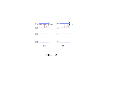
Atom-cavity dispersive interaction.—Consider atoms () with four levels depicted in Fig. 2(a). The cavity mode is coupled to the transition of
each atom but highly detuned (decoupled) from the transition between any
other two levels [Fig. 2(a)]. In the interaction picture, the interaction
Hamiltonian is given by
(1)
where is the detuning of the cavity
frequency with the transition frequency of the atoms, is
the coupling constant between the cavity mode and the transition, and
For (i.e., the cavity mode is dispersively coupled to the
transition of
each atom), no energy exchange occurs between the atoms and the
cavity mode. In this case, when the level of each
atom is not excited, the Hamiltonian (1) becomes [8-10]
(2)
The time-evolution operator corresponding to is given by where acts on
the cavity mode and atom (). It is easy to verify that
for leads to the
transformation while leaves the states and unchanged. Here, is the single-photon state of the cavity.
Atom-pulse dispersive interaction—Consider a four-level atom ,
which is driven by a pulse with frequency and initial phase The pulse is coupled to the transition of atom with a detuning [Fig. 2(b)], which is described by
(3)
where is the pulse Rabi frequency. For ,
the Hamiltonian (3) becomes under which a pulse of duration leads
to
with The is adjustable by
changing the Rabi frequency or the duration of the pulse.
Gate implementation—Consider a two-level atom with two levels
(ground) and (excited),
and identical atoms () with four levels depicted in Fig. 2.
For each atom, the two lowest levels and represent the two logical states of a qubit.
Our gate operation needs to move atoms into or out of the cavity. This can
be achieved by employing a translating optical lattice trap [11,12].
Experimentally, using an optical lattice trap to deliver atoms or a single
atom into an optical microcavity has been reported [12], and by controlling
the motion of the standing wave, a single atom can be transported to a
preselected point along the standing wave with a very high precision [11].
We suppose that during the gate operation, (i) the cavity mode is resonant
with the
transition of atom with a coupling constant and (ii) the cavity
mode is dispersively coupled to the transition of atoms () but highly
detuned (decoupled) from the transition between any other two levels of
atoms (). In addition, the following gate operation involves
the application of a classical pulse resonant to the transition (with frequency ) of atoms (). The pulse Rabi frequency is denoted as The frequency, initial phase, and duration of the resonant pulse
are denoted as { } below.
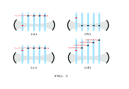
Figure 3: (Color online) Proposed setup for the gate realization with the
control atom (the red dot), the identical target atoms (the dark dots),
and a cavity. For simplicity, only five atoms are drawn here. Each atom can
be trapped and loaded into or out of the cavity by a one-dimensional
translating optical lattice trap [11,12].
The cavity mode is initially in the vacuum state
The procedure for realizing the gate is as follows:
Step (i): Apply a pulse of to atoms (), to transform the state of atom to (). Meanwhile, move atom
into the cavity for a time [Fig. 3(a)], to transform the
state to but leave the state unchanged. Then, move atom
out of the cavity.
Step (ii): Move atoms () into the cavity for a time [Fig. 3(b)]. As a result, the states and remain unchanged; but the state changes to () as discussed
previously. Then, move atoms () out of the cavity.
Step (iii): Apply a pulse of to atoms (), to transform the
state of atom
to while the state to ().
Step (iv): Adjust the positions of atoms () (e.g., by
translating optical lattices) such that the atoms are sufficiently separated
in space and then apply a classical pulse to each of them [Fig. 3(d)]. Each
pulse has the same frequency and a zero initial phase. The pulse applied to
atom () is off-resonant with the transition of atom with a
detuning which has a Rabi frequency and a duration As discussed previously, a phase shift on the state of atom
is obtained after the pulse is applied to atom Note that
can be adjusted by changing the pulse Rabi frequency
Step (v): Adjust the positions of the atoms () back to
the original positions as depicted in Fig. 3(c) and then apply a pulse of to atoms (), to transform the state of atom
to the state
while the state to () .
Step (vi): Move atoms () back into the cavity for a
time [Fig. 3(b)]. The results for this step of operation
are the same as those given in step (ii). Then, move the atoms () out of the cavity.
Step (vii): Apply a pulse of to atoms () [Fig. 3(a)], to transform the
state of atom
to (). Meanwhile, move atom
back into the cavity for a time [Fig. 3(a)], such that the
state changes to while the state remains unchanged. Then, move
atom out of the cavity.
One can check that the -qubit phase gate depicted in Fig. 1(a) was
obtained with atoms (i.e., the control atom 1 and the target atoms
and ) after the above manipulation.
Simultaneous interaction of a pulse with all of the target atoms () during steps (i), (iii), (v), and (vii) is unnecessary.
Instead, one can apply a pulse to each or part of the atoms ()
separately.
For step (iv), one can also set In this case,
which can be tuned by changing the duration of the pulse applied
to atom
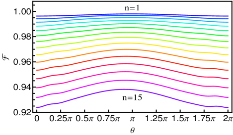
Figure 4: (Color online) Fidelity versus .
Lines from top to bottom correspond to , ,…, and ,
respectively. Here, is the number of target atoms ().
Due to non-exact placement of each atom in a preselected point of the cavity
axis, the real coupling constant () between the target
atom (the control atom ) and the cavity may be different from the
ideal () above. Hence, it is necessary to investigate how the gate
fidelity is affected by the deviation of the real coupling constants from
the ideal ones. The fidelity is defined by where and are the states of the
system after the above operations for the ideal case and the nonideal case,
respectively. For the latter case, the effective Hamiltonian, associated
with steps (ii) and (vi), takes the same form as the Hamiltonian (2) with replaced by . As an example, consider that each atom is initially in
the state before the gate. One can easily work out the states and (not shown to simplify
our presentation). We have plotted Fig. 4 to demonstrate how the fidelity
changes versus for (), and . Fig. 4 shows
that the gate fidelity decreases as the number of target qubits
increases but a high fidelity or more can be achieved when
Multiqubit phase gate in QFT—For a two qubit CP gate described by
and it is obvious that the
roles of the two qubits can be interchanged. Thus, the multiqubit phase gate
in Fig. 1(a) is equivalent to the one with -control qubits (qubits ) acting on one target qubit (qubit ) [Fig. 1(b)]. The gate
in Fig. 1(b), with (), plays an
important role in quantum Fourier transforms (QFT). To implement this
gate, the pulse Rabi frequencies and , involved in step (iv), need to satisfy the relation (), and the operation time
for step (iv) needs to be set by
In this way, one can obtain
().
Fidelity—Steps (i), (iii), (v), and (vii) can be completed within
a very short time because of using resonant interactions only. Thus the
dissipation of the atoms () and the cavity for these steps is
negligibly small. One can choose atom with sufficiently long spontaneous
emission time such that decoherence of this atom is negligible during the
entire operation. Thus, the dissipation of the system
would appear in steps (ii) and (vi) due to the use of the atom-cavity or
atom-pulse dispersive interaction.
During step (ii) or step (vi), the dynamics of the lossy system, composed of
the cavity mode and atoms (), is determined by
(4)
where is the Hamiltonian (1) with replaced by ,
(with , and ),
is the decay rate of the cavity mode, is the decay
rate of the level of atoms () via the
decay path (here,
). In addition, during step (iv), the dynamics
of the lossy system, composed of the cavity mode and atoms (), is described by where is the Hamiltonian (3) and is the
sum of the last four terms of Eq. (4).
The fidelity of the gate operations is given by where is the state of the whole system after the
gate operations, in the ideal case without considering the dissipation of
the system during the entire operation and non-exact placement of atoms
inside the cavity; and is the final density operator of
the whole system after the gate operations are performed in a real situation.
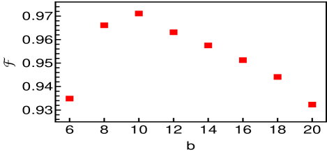
Figure 5: (Color online) Fidelity versus . Here,
As an example, let us consider realizing a four-qubit CP gate in QFT, using
a two-level atom and three identical four-level atoms (). The
three identical atoms () are chosen as Rydberg atoms with the
principle quantum numbers 49, 50, and 51, which correspond to the three
levels and as depicted in Fig. 2, respectively. We label the energy
relaxation times for the three levels and by and which are on the order of s (e.g., see [13-15]). Without loss of generality, assume that each
of the four atoms is initially in the state and the cavity mode is in the
vacuum state before the gate. The expression for the ideal state of the system after the entire operation is
straightforward (not shown here to simply our presentation). As a
conservative estimation, consider and . In
addition, choose , , KHz [13,14], s (a typical time for loading
atoms into or out of the cavity), and s.
Our numerical calculation shows that a high fidelity can be
achieved when the ratio is about 10
(Fig. 5).
For Rydberg atoms chosen here, the transition frequency is GHz [15]. The
cavity mode frequency is then GHz for . For
the cavity-photon lifetime used in our calculation, the
required quality factor of the cavity is Note that cavities with a high
was previously reported [16].
Discussion—The idea of coupling qubits to a cavity to implement
the proposed gate was previously presented [17]. However, our present
proposal differs from the one in [17]. First, in our present proposal,
application of pulses to the qubits is carried out outside a
cavity, while the one in [17] requires that each pulse was applied to a
different target qubit inside a cavity. Second, the present
proposal is based on a first-order large detuning, i.e., or
, while the proposal in [17] was based on a
second-order large detuning between the cavity mode and the pulse (for the
detailed discussion, see [17]).
Acknowledgments.—This work was supported in part by the National
Natural Science Foundation of China under Grant Nos. 11074062, 11147186,
11174081 and 11034002, the National Basic Research Program of China under
Grant No. 2011CB921602, the Zhejiang Natural Science Foundation under Grant
No. Y6100098, and the Open Fund from the SKLPS of ECNU.
References
(1) L. M.Duan et al., Phys. Rev.A 72, 032333 (2005).
(2) X. M. Lin et al., G. C. Guo, Phys. Rev. A
73, 012323 (2006); Y. F. Xiao et al., Phys. Rev. A 75, 014302 (2007);
Phys. Rev. A 75, 054303 (2007); G. W. Lin et al.,
Phys. Rev. A 79, 064303 (2009).
(3) X. Wang et al., Phys. Rev. Lett. 86, 3907 (2001).
(4) C. P. Yang et al., Phys. Rev. A 72, 032311 (2005).
(5) C. P. Yang et al., Phys. Rev. A 73, 032317 (2006).
(6) H. Z. Wu et al., Phys. Rev. A 82, 034307
(2010).
(7) W. L. Yang et al., Appl. Phys. Lett. 96, 241113 (2010).
(8) S. B. Zheng et al., Phys. Rev. Lett. 85, 2392 (2000).
(9) S. B. Zheng, Phys. Rev. Lett 87, 230404 (2001).
(10) A. Sørensen et al., Phys. Rev. Lett. 82, 1971
(1999).
(11) S. Kuhr et al., Science 293, 278 (2001).
(12) J. A. Sauer et al., Phys. Rev. A 69, 051804(R) (2004).
(13) M. Brune et al., Phys. Rev. Lett. 77, 4887 (1996).
(14) S. Osnaghi et al., Phys. Rev. Lett. 87, 037902 (2001).
(15) X. B. Zou et al., Phys. Rev. A 72, 013809 (2005).
(16) G. Rempe et al., Phys. Rev. Lett. 64 2783 (1990).
(17) C. P. Yang et al., Phys. Rev. A 82, 062326
(2010).