Controlled catch and release of microwave photon states
Abstract
The quantum behavior of superconducting qubits coupled to resonators is very similar to that of atoms in optical cavities kimble:1998 ; haroche:2006 , in which the resonant cavity confines photons and promotes strong light-matter interactions. The cavity end-mirrors determine the performance of the coupled system, with higher mirror reflectivity yielding better quantum coherence, but higher mirror transparency giving improved measurement and control, forcing a compromise. An alternative is to control the mirror transparency, enabling switching between long photon lifetime during quantum interactions and large signal strength when performing measurements. Here we demonstrate the superconducting analogue, using a quantum system comprising a resonator and a qubit, with variable coupling to a measurement transmission line. The coupling can be adjusted through zero to a photon emission rate 1,000 times the intrinsic photon decay rate. We use this system to control photons in coherent states as well as in non-classical Fock states, and dynamically shape the waveform of released photons. This has direct applications to circuit quantum electrodynamics schoelkopf:2008 , and may enable high-fidelity quantum state transfer between distant qubits, for which precisely-controlled waveform shaping is a critical and non-trivial requirement cirac:1997 ; korotkov:2011 .
Superconducting resonators play a central role in quantum information technology. Applications include the synthetic generation and storage of photon quantum states hofheinz:2008 ; hofheinz:2009 ; wang:2009b , quantum memories for quantum computation mariantoni:2011 , and dispersive measurements of superconducting qubits blais:2004 ; wallraff:2005 as well as defects in diamond kubo:2010 ; schuster:2010 . Resonators with low internal losses are typically desirable, but the resonator’s coupling strength to the quantum system and to its measurement apparatus is application-dependent. When coupling a resonator to a qubit, either for a quantum memory or in a circuit quantum electrodynamics experiment, strong coupling to the qubit improves information transfer but also increases dephasing. When reading out a qubit, coupling the resonator strongly to its measurement apparatus increases the measurement bandwidth and signal but in addition increases dissipation mallet:2009 . Resonator designs therefore involve compromises between the competing needs for both strong and weak coupling johnson:2010 ; leek:2010 . A resonator with a variable coupling would provide a significant improvement: If used to measure a qubit, the coupling to the measurement apparatus could be turned off except during resonator readout, when the coupling could be made large. When coupling two qubits through a resonator, the coupling could be turned on and off as needed allman:2010 ; srinivasan:2011 , yielding higher fidelity gates cirac:1997 ; korotkov:2011 .
Here we employ an externally-controlled variable inductance bialczak:2011 to modulate the coupling of a resonator to a transmission line, creating the microwave equivalent of a Fabry-Perot cavity with a variable-transparency mirror. The resonator also has fixed coupling to a superconducting phase qubit. We demonstrate the time-controlled release of single-photon Fock and superposition states, thus generating a “flying qubit” boyzigit:2011 ; houck:2007 ; divincenzo:2000 . We also perform timed capture and release of few-photon coherent states, and use the variable coupling to transmit and release photons with arbitrary waveforms lukin:2003 ; keller:2004 . This new capability promises numerous applications in high-fidelity quantum computing and communication.
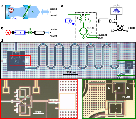
The schematic in Fig. 1a displays a Fabry-Perot cavity, which represents the resonator, with a tunable transparency mirror to represent the variable coupler. A two-level atom plays the role of the qubit. In the actual experiment (Fig. 1b, c and d), the resonator () is a quarter-wavelength () coplanar waveguide resonator, with one end coupled to a superconducting phase qubit () and the other end shorted to ground. Close to the grounded end (a distance away), the resonator is connected to a variable coupler (), which modulates the inductive coupling to a microwave transmission line. The variable coupler is controlled using a bias current, which flux-modulates the inductance of a superconducting quantum interference device (SQUID) embedded in a mutual inductance circuit. The resonator-transmission line coupling can vary from zero to a maximum emission rate , over a time scale of a few nanoseconds. The resonator frequency is GHz, and the phase qubit has a ground to excited state () transition frequency tunable from to 7 GHz hofheinz:2009 ; bialczak:2011 ; yin:2012 . The qubit-resonator coupling is MHz, measured using swap spectroscopy mariantoni:2011 . The qubit-resonator interaction is controlled by tuning the qubit frequency, and is effectively turned off by setting the qubit frequency to its idle point, MHz below the resonator frequency hofheinz:2009 ; bialczak:2011 ; yin:2012 .
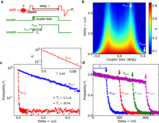
The resonator and variable coupler were characterized by measuring the decay of a one-photon Fock state stored in the resonator. When the resonator is weakly coupled to the transmission line, the photon decays due to internal resonator losses, while when strongly coupled, the photon is emitted into the transmission line. The pulse sequence is shown in Fig. 2a, where the qubit was excited from to , and the excitation then swapped to the resonator, creating a one-photon Fock state hofheinz:2009 . The coupler bias current was then adjusted, and after a delay time , the residual excitation swapped back to the qubit, and the qubit measured.
Figure 2b displays the probability of measuring the qubit in as a function of delay and the variable coupler current bias. decays exponentially with time , with the decay rate varying strongly with coupler bias. Two line cuts are shown in Fig. 2c, with exponential fits yielding the resonator lifetime . For zero coupling, as determined from maximizing with respect to coupler bias, we find the intrinsic s, in agreement with resonator loss measurements, while for coupling the lifetime is reduced to ns. The resonator inverse lifetime is the sum of the intrinsic decay rate and the coupler emission rate , so . The coupling dependence on current bias in Fig. 2b is in good agreement with calculations (Supplementary Information).
We demonstrated dynamic control by changing the coupling during the delay period, as shown in Fig. 2d. We started with the coupling set to zero, and after a delay switched the coupling to . The reduction in the photon lifetime after the switch is clearly visible. The coupler switching speed was limited by the ns rise time of the coupler bias, roughly 2,000 times shorter than .
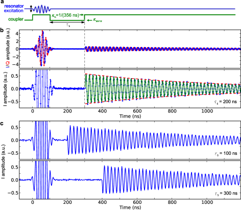
This measurement does not distinguish between incoherent decay and the expected phase-coherent release of the photon. We therefore also used heterodyne detection, with the resonator “catching” and then “releasing” photons in coherent states. Figure 3a displays the pulse sequence: With the coupler set to an intermediate coupling , we excited the resonator with a 100 ns Gaussian pulse from the microwave source, with the pulse calibrated to trap photons (see Supplementary Information). The coupling was then set to zero, trapping the photons for a storage time , then set back to , releasing the photons for heterodyne detection.
Figure 3b shows the heterodyne-detected signal in the (real) and (imaginary) quadratures in the time domain. During the Gaussian excitation pulse, the signal comprised the reflected component of the excitation. No signal was detected during the subsequent ns storage time with the coupler turned off. A sharp onset followed by an exponentially-decaying envelope appeared when the coupler was turned back on, releasing the photons. The signal envelope has a decay time ns, in close agreement with the expected value ns. The amplitude oscillations are from a 50 MHz mixer sideband signal, and the and quadratures have a relative offset, as expected. As the output traces were averaged times, the presence of oscillations indicates that the output represents coherent photon release, with a fixed output phase relative to the input.
Figure 3c displays the quadratures using storage times and 300 ns. These are identical during the state-generating Gaussian pulse, but during the release the oscillation phase depends on the storage time , scaling as . This phase accumulation is as expected from the small tuning of the resonator frequency with coupler bias (see Supplementary Information), further demonstrating the coherence of the release.
We also calculated the radiated energy , integrating the signal power from the photon release time to a cutoff . We find that the released energy for ns is 4% lower than for ns, in agreement with the expected intrinsic resonator loss.
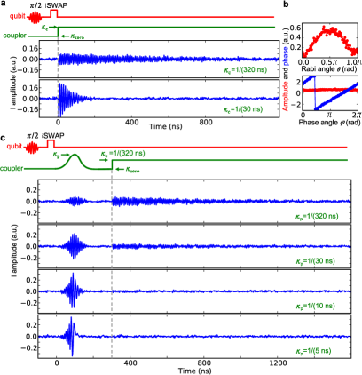
These measurements confirm the phase-coherent capture and release of coherent states. To demonstrate that we can achieve the same control for non-classical states, we used the qubit to generate hofheinz:2009 the photon superposition state and measured the release signal after turning on the coupling (Fig. 4a). For an intermediate coupling and a large coupling , the signal’s exponential decay envelope has a time constant ns and 69 ns, respectively, close to the expected , verifying that the coupling determines the release rate. The integrated energy for intermediate coupling is lower than for large coupling, attributed to greater intrinsic loss from the slower release.
We next tested the release and detection of the qubit-prepared superposition state , akin to previous work with static coupling boyzigit:2011 ; houck:2007 . The released photons were heterodyne-detected as a function of the Rabi angle and the phase angle , with Fourier transforms of and yielding the signal amplitude and phase. Figure 4b shows the dependence of the signal amplitude on , with . The maximum amplitude is at , corresponding to . The amplitude goes to zero for the pure Fock states at and as expected, due to the loss of phase-coherence at the Bloch sphere poles. When releasing the state with and varying , the signal has constant amplitude and phase increasing linearly with .
The on-demand, real-time gating of the coupler enables precise shaping of the photon release waveform. Figure 4c shows the tailored time-dependent release of the photon state, modulating the coupling with a 200 ns Gaussian bias pulse with peak coupling , followed by a 100 ns delay and then completing the release with . Figure 4c shows the quadrature signal for , , and , with a Gaussian-like release waveform mimicking the coupler pulse. For the top three sub-panels, energy integrals show that , and of the total stored energy is released during the pulse, with the remainder released after the ns delay. For couplings , the release is completed during the Gaussian pulse. In contrast to fixed coupling, in which the waveform decays exponentially with time, the bottom sub-panel shows an exponential-like increase of the waveform, as needed for high-fidelity transfer of photonic information cirac:1997 ; korotkov:2011 .
We have demonstrated the phase-coherent, controlled capture and release of coherent and superposition photon states from a resonator, using a resonator-transmission line variable coupling. This powerful technique should allow long-range entanglement mariantoni:2011 ; wang:2011 ; neeley:2010 ; ritter:2012 ; duan:2001 ; briegel:1998 , where the shaped release we display in the last experiment is a key ingredient for high-fidelity state transfer cirac:1997 ; korotkov:2011 . This capability will further enable tunable coupling for resonator-based dispersive qubit readout, where time-domain control can minimize deleterious dephasing while maximizing measurement bandwidth and signal strength.
Acknowledgements This work was supported by IARPA under ARO Award No. W911NF-08-01-0336 and under ARO Award No. W911NF-09-1-0375. M.M. acknowledges support from an Elings Postdoctoral Fellowship. R.B. acknowledges support from the Rubicon program of the Netherlands Organization for Scientific Research. Devices were made at the UC Santa Barbara Nanofabrication Facility, a part of the NSF funded National Nanotechnology Infrastructure Network.
Author Contributions Y.Y. designed and fabricated the samples, carried out the experiments and analyzed the data. Y.Y. co-wrote the paper with J.M.M. and A.N.C., who also supervised the project. Y.C. and D.S. developed the control infrastructure of a custom-designed, FPGA-controlled ADC board. D.S. and P.J.J.O. provided assistance with data-taking software. T.W. set up and calibrated the amplifier chain. A.N.K. developed the theoretical model. All authors contributed to the fabrication process, experimental set-up and manuscript revision.
References
- (1) Kimble, H. J. Strong interactions of single atoms and photons in cavity QED. Physica Scripta 1998, 127 (1998).
- (2) Haroche, S. & Raimond, J.-M. Exploring the Quantum: Atoms, Cavities and Photons (Oxford University Press, Oxford UK, 2006).
- (3) Schoelkopf, R. J. & Girvin, S. M. Wiring up quantum systems. Nature 451, 664–669 (2008).
- (4) Cirac, J. I., Zoller, P., Kimble, H. J. & Mabuchi, H. Quantum state transfer and entanglement distribution among distant nodes in a quantum network. Phys. Rev. Lett. 78, 3221–3224 (1997).
- (5) Korotkov, A. N. Flying microwave qubits with nearly perfect transfer efficiency. Phys. Rev. B 84, 014510 (2011).
- (6) Hofheinz, M. et al. Generation of Fock states in a superconducting quantum circuit. Nature 454, 310–314 (2008).
- (7) Hofheinz, M. et al. Synthesising arbitrary quantum states in a superconducting resonator. Nature 459, 546–549 (2009).
- (8) Wang, H. et al. Decoherence dynamics of complex photon states in a superconducting circuit. Phys. Rev. Lett. 103, 200404 (2009).
- (9) Mariantoni, M. et al. Photon shell game in three-resonator circuit quantum electrodynamics. Nature Physics 7, 287–293 (2011).
- (10) Blais, A., Huang, R.-S., Wallraff, A., Girvin, S. M. & Schoelkopf, R. J. Cavity quantum electrodynamics for superconducting electrical circuits: An architecture for quantum computation. Phys. Rev. A 69, 062320 (2004).
- (11) Wallraff, A. et al. Approaching unit visibility for control of a superconducting qubit with dispersive readout,. Phys. Rev. Lett. 95, 060501 (2005).
- (12) Kubo, Y. et al. Strong coupling of a spin ensemble to a superconducting resonator. Phys. Rev. Lett. 105, 140502 (2010).
- (13) Schuster, D. I. et al. High-cooperativity coupling of electron-spin ensembles to superconducting cavities. Phys. Rev. Lett. 105, 140501 (2010).
- (14) Mallet, F et al. Single-shot qubit readout in circuit quantum electrodynamics. Nature Physics 5, 791–795 (2009).
- (15) Johnson, B. R. et al. Quantum non-demolition detection of single microwave photons in a circuit. Nature Physics 6, 663–667 (2010).
- (16) Leek, P. J. et al. Cavity quantum electrodynamics with separate photon storage and qubit readout modes. Phys. Rev. Lett. 104, 100504 (2010).
- (17) Allman, M. S. Altomare, F. Whittaker, J. D. Cicak, K. Li, D. Sirois, A. Strong, J. Teufel, J. D. & Simmonds, R. W. rf-SQUID-mediated coherent tunable coupling between a superconducting phase qubit and a lumped-element resonator. Phys. Rev. Lett. 104, 177004 (2010).
- (18) Srinivasan, H. A. Hoffman, A. J. Gambetta, J. M. & Houck, A. A. Tunable coupling in circuit quantum electrodynamics using a superconducting charge qubit with a V-shaped energy level diagram. Phys. Rev. Lett. 106, 083601 (2011).
- (19) Bialczak, R. C. et al. Fast tunable coupler for superconducting qubits. Phys. Rev. Lett. 106, 060501 (2011).
- (20) Bozyigit, D. et al. Antibunching of microwave-frequency photons observed in correlation measurements using linear detectors. Nature Physics 7, 154–158 (2011).
- (21) Houck, A. A. et al. Generating single microwave photons in a circuit. Nature 449, 328–331 (2007).
- (22) Divincenzo, D. P. The physical implementation of quantum computation. Fortschr. Phys 48, 2000 (2000).
- (23) Lukin, M. D. Colloquium: Trapping and manipulating photon states in atomic ensembles. Rev. Mod. Phys. 75, 457–472 (2003).
- (24) Keller, M. Lange, B. Lange, W. & Walther, H. Continuous generation of single photons with controlled waveform in an ion-trap cavity system. Nature 431, 1075–1078 (2004).
- (25) Yin, Y. et al. Dynamic quantum Kerr effect in circuit quantum electrodynamics. Phys. Rev. A 85, 023826 (2012).
- (26) Wang, H. et al. Deterministic entanglement of photons in two superconducting microwave resonators. Phys. Rev. Lett. 106, 060401 (2011).
- (27) Neeley, M. et al. Generation of three-qubit entangled states using superconducting phase qubits. Nature 467, 570–573 (2010).
- (28) Ritter, S. et al. An elementary quantum network of single atoms in optical cavities. Nature 484, 195–200 (2012).
- (29) Duan, L.-M., Lukin, M. D., Cirac, J. I. & Zoller, P. Long-distance quantum communication with atomic ensembles and linear optics. Nature 414, 413–418 (2001).
- (30) Briegel, H.-J., Dür, W., Cirac, J. I. & Zoller, P. Quantum repeaters: The role of imperfect local operations in quantum communication. Phys. Rev. Lett. 81, 5932–5935 (1998).