Behaviour in Magnetic Fields of Fast Conventional and Fine-Mesh Photomultipliers.
Abstract
The performance of both conventional and fine-mesh Hamamatsu photomultipliers has been measured inside moderate magnetic fields. This has allowed the test of effective shielding solutions for photomultipliers, to be used in time-of-flight detectors based on scintillation counters. Both signal amplitude reduction or deterioration of the timing properties inside magnetic fields have been investigated.
keywords:
time-of-flight detectors , photomultipliers1 Introduction
A simple parametrization of the timing resolution of time-of-flight (TOF) detectors, based on scintillation counters, is given in references [1, 2]:
| (1) |
where: is the scintillator response, the photomultiplier (PMT) jitter, the path lengths variations, the jitter of the electronic readout system and is the average number of photoelectrons. The dominant factors for are and the counter dimensions (mainly its length L), responsible for path lengths fluctuations. Below 100 ps, contributions such as become increasingly important.
As the PMT signals of a TOF system are commonly fed into a time-to-digital converter (TDC) after a leading edge discriminator, a relevant reduction in PMT gain (as happens inside magnetic fields) is to be avoided, to prevent increasing and less reliable time-walk corrections.
As a consequence, the operation inside even moderate magnetic fields (up to some hundreds of Gauss), such as stray fields of magnets, puts severe requirements on the properties of the used photomultipliers, for what concerns gain and timing properties. The more common solution for conventional PMTs is to use local shieldings, made of a cylindrical envelope of high permeability material, such as metal. The shielding factor is proportional to the relative magnetic permeability of the used material multiplied by some (non-negligible) geometric factor. High permeability alloys are available, but saturation effects limit their use to low external magnetic fields (up to 50-100 Gauss). To reduce this effect the shield radius may be increased. As these materials are quite expensive, a common solution is to use in addition to a thin, high permeability inner shield, a thick soft iron external shield. These composite shieldings are quite effective to suppress the orthogonal component of the magnetic field , but problems may arise for the axial component , parallel to the PMT axis. While formulas to compute the “shielding factor” for orthogonal fields are easily available [3], results for the shielding of the axial component of a magnetic field are less common.
Fine-mesh dynodes PMTs are instead nearly insensitive to the axial component of the magnetic field , but may have problems with an increasing transverse component . These tubes become totally unusable for orientations of the PMT axis, with respect to the magnetic field, bigger than a critical value () even in small magnetic fields ( Gauss). The structure of these PMTs is based on a sequence of fine-mesh electrodes, where the incoming electrons are multiplied by secondary emission. The electrons in the final stage are collected by the anode as output signal. The distance between the first dynode and the photocathode is mm, while the distance between successive dynodes is mm.
In the following, results on conventional 1” R4998 and R9800 PMTs and fine mesh 1”, 1.5”, 2” R5505, R7761 and R5924 PMTs from Hamamatsu will be shown (see table 1 for their main properties).
They have been of interest in detector optimization for the timing counter [4] of the MEG experiment at PSI [5] and the TOF detectors [6, 7] of the MICE experiment at RAL [8], devised to study ionization cooling for the proposed Neutrino Factory [9] and Muon Collider [10].
| R4998 | R9800 | R5505 | R7761 | R5924 | |
| PMT type | conventional | conventional | fine-mesh | fine-mesh | fine-mesh |
| Tube diameter | 1” | 1” | 1” | 1.5” | 2” |
| No. stages | 10 | 8 | 15 | 19 | 19 |
| Q.E. at peak | .20 | .25 | .23 | .23 | .22 |
| Gain (B=0 T) typ. | |||||
| transit time (ns) | 10 | 11 | 5.6 | 7.5 | 9.5 |
| Risetime (ns) | 0.7 | 1.0 | 1.5 | 2.1 | 2.5 |
| TTS (ns) | 0.16 | 0.27 | 0.35 | 0.35 | 0.44 |
| HV (V) (max value) | -2500 | -1500 | +2300 | +2300 | +2300 |
All PMTs were delivered as assemblies with a passive or active divider base and a 1 mm-thick -metal shield.
For PMT timing the relevant properties are the transit time spread (TTS) and the PMT size that may have an effect on it, by an increasing photocathode area (with a wider photoelectrons spatial distribution). For this reason this paper will report mainly about the smaller size (1”) PMTs, that have better timing properties.
2 Test results for conventional PMTS
Systematic studies of conventional PMTs have been performed, using a built on purpose solenoid of 23 cm inner diameter, 40 cm length 111 TBM srl, Uboldo (VA), Italy. The solenoid being a resistive magnet, special care was put into the thermal resistance of the assembly (up to ), using special insulating paints. For part of the tests a Digimess 3040 laboratory power supply (0-32 V, 0-40 A) was used. For larger field amplitudes an Eutron power supply (0-32 V, 0-100 A) was employed. The main constraint was the heating of the windings that limited the maximum circulating current to about 55 A (corresponding to a maximum field of 600 Gauss), due to the increase of conductor resistance giving higher voltage drops (up to the maximum allowed value of ). The large open bore allows tests both with field lines orthogonal or parallel to the PMT axis.
The magnetic field was measured with a gaussmeter 222 Hirst GM04 model, with transverse Hall probe, with a relative accuracy better than . The B field calibration curve is shown in figure 1 at the center of the solenoid and at different positions shifted along its longitudinal axis.
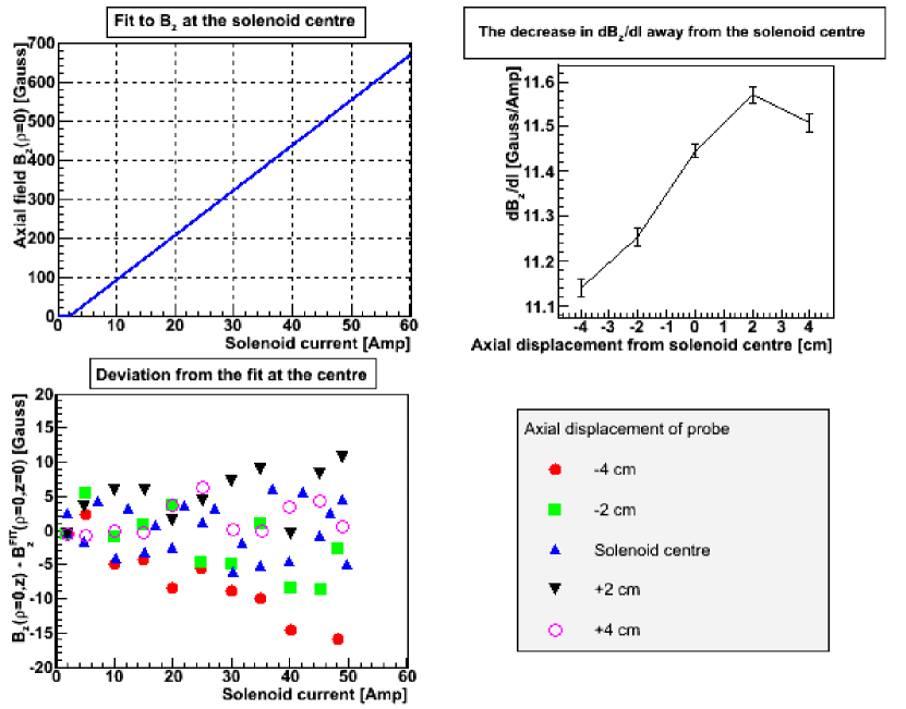
From simulations using a finite length solenoid approximation and performed measurements, a field uniformity better than may be assumed at the center of the test solenoid in a volume of about .
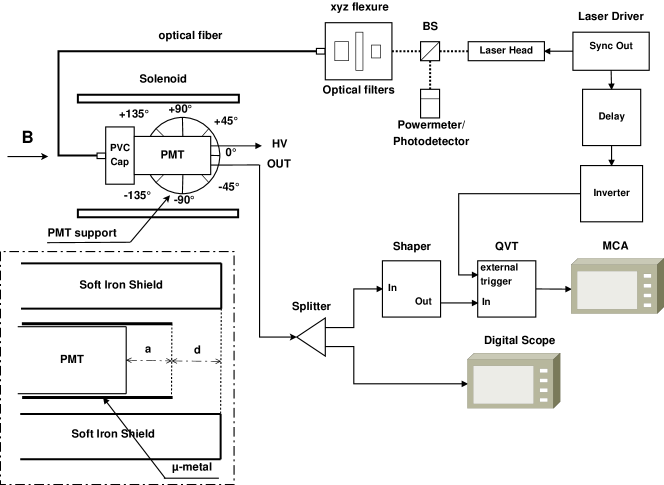
A fast light pulse ( ns width, to simulate a typical scintillator signal) 333 The system is based on a Nichia NDHV310APC violet laser diode, driven by an AvtechPulse fast pulser (type AVO-9A-C, with ps risetime) and an AVX-S1 output module. Laser pulses at , with a FWHM between ps and ns were obtained. was sent to the centre of the PMT photocathode via a 3 m long multimode 3M TECS FT-110-LMT optical fiber 444with a measured dispersion of ps/m, see [13]. inserted in a small Plexiglas cover in front of the PMT window. To provide light signals of various intensities, the laser spot was injected into the optical fiber by a 10x Newport microscope objective, after removable absorptive neutral density filters. A broadband beamsplitter (BS) divided the laser beam to give of light on the fiber injection system and on a fast Thorlabs DET10A photodiode (risetime ns), to monitor the laser system stability. Tests were carried out with a signal corresponding to about 150-300 photoelectrons 555The number of photoelectrons () was estimated via absolute gain measurement. This number was cross-checked with powermeter measurements.: a typical value for a minimum ionizing particle (MIP) crossing a 1” to 2”-thick scintillator. The optical power was periodically monitored with an OPHIR NOVA laser powermeter.
The experimental setup is shown in figure 2. The PMT signal was input after a passive splitter to a digital scope 666 Tektronix TDS 754C with 500 MHz bandwidth, 2 Gs/s sampling rate or Tektronix DPO7254 with 2.5 GHz bandwith, 40 Gs/s sampling rate. triggered by the laser synchronization output signal (sync. out) with a maximum jitter of ps with respect to the delivered optical pulse and to a Silena 8950 Multichannel Analyzer (MCA). For timing measurements, the MCA chain was used with a Silena 7422 charge-amplitude-time converter (QVT). The PMT anode signal after a leading edge PLS 707 discriminator provided the STOP signal (), while the START signal () was given by the sync out of the laser pulser after a suitable delay and an ORTEC pulse inverter.
In timing measurements, the time difference is measured. This accounts for delay in cables and electronics and jitter in the transit time in the tested PMTs. No variation of this quantity or no deterioration in the FWHM of its distribution, after increasing the magnetic field intensity, demonstrates the effectiveness of the adopted shielding solution.
2.1 Experimental results
As conventional photomultipliers may work without major problems inside a residual magnetic field of a few Gauss, a preliminary estimate of their expected behaviour may be obtained from magnetostatics simulations.
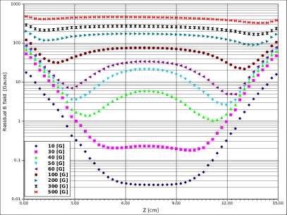
The residual longitudinal magnetic field inside a -metal shielding or a composite shielding made of a soft iron cylinder surrounding a mu-metal shield may be easily calculated with 2-D magnetostatics simulation programs. Results are reported in figure 3 as an example, using the public domain 2-D magnetostatics program FEMM 4.2 [11]. From the reported simulation results, it is evident that the more the PMT is moved inside the external shielding, the smaller is the value of the sensed residual magnetic field up to a plateau. This reduction, for the metal shielding works only up to fields Gauss, where the residual magnetic field begins to increase again.
The situation is more difficult to handle for composite shieldings with no azymuthal symmetry, such as the ones with box-shaped soft iron external shieldings (discussed later), where more complicate 3-D magnetostatics programs may be needed.
In these cases we prefer to rely on experimental results, such as the ones reported in the following. The PMTs under test were put in the central region of the solenoid, using a support to incline them from to with respect to the magnet field lines (from B∥ to B⟂). Environment light was accurately masked, to reduce noise. Measurements were performed to see gain reduction and possible deterioration in timing resolution as a function of the magnetic field value (B) and the relative orientation angle (), between the PMT axis and the magnetic field. The tested shielding solutions were the -metal shielding only option (1 mm thick -metal) and various options with additional shields made of soft iron 777 with typical relative permeability and a reduced area hysteresis loop in box or cylindrical shapes. As the magnetic shielding is mainly a “mass effect” we may expect, for similar transverse dimensions, box-shaped shieldings to be more effective than cylindrical ones, having more shielding mass 888This idea was pionereed by the the D0 experiment in reference [12].. The tests have been carried out with various shielding configurations:
-
1.
only -metal 999with a maximum relative permeability . shielding (1 mm thick, 15 cm long: extending 3 cm beyond the photocathode area);
-
2.
a 15 cm long iron cylinder of diameter 5 or 6 cm with a central hole of 3.2 cm diameter (to accomodate inside the PMT assembly with a 1 mm thick metal shielding) made of Fe 360 soft iron 101010S235JR unalloyed steel for magnetic applications, with a maximal carbon content of and a maximum relative permeability .;
-
3.
a 15 cm long iron box of transverse area or with a central hole of 3.2 cm diameter (to accomodate the PMT assembly) made of different iron types: Fe360 soft iron or Armco. 111111 ARMCO from AkSteel is a pure iron with maximal carbon content of and a magnetic saturation (J=B-H) of 2.15 Wb/, much higher than available commercial soft iron. Its maximum relative permeability is .
-
4.
the previous two configurations, moving the PMT assembly 1, 2 or 3 cm inside the edge of the iron shielding
Results with only the -metal shielding were reported in reference [6] and show that R4998 PMTs perform satisfactorily for longitudinal B∥ fields up to Gauss and for orthogonal B⟂ fields up to Gauss.
Inside an orthogonal magnetic field B⟂, no effect larger than a few per-cent is seen for fields up to 500-600 Gauss using any of the previously described composite shieldings.
So we focussed our efforts only on the study of PMTs inside longitudinal magnetic fields.
Figure 4 (top left-hand panel) shows the signal reduction for a typical R4998 PMT, with different shielding options: -metal only or -metal with additional soft iron shieldings, in a longitudinal magnetic field B∥. For equivalent shield sizes, the box-shaped iron shielding is clearly more effective than the conventional cylindrical one.


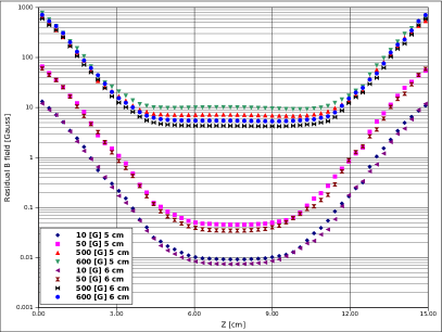
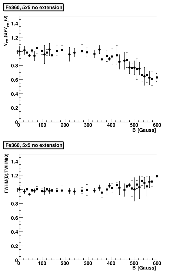
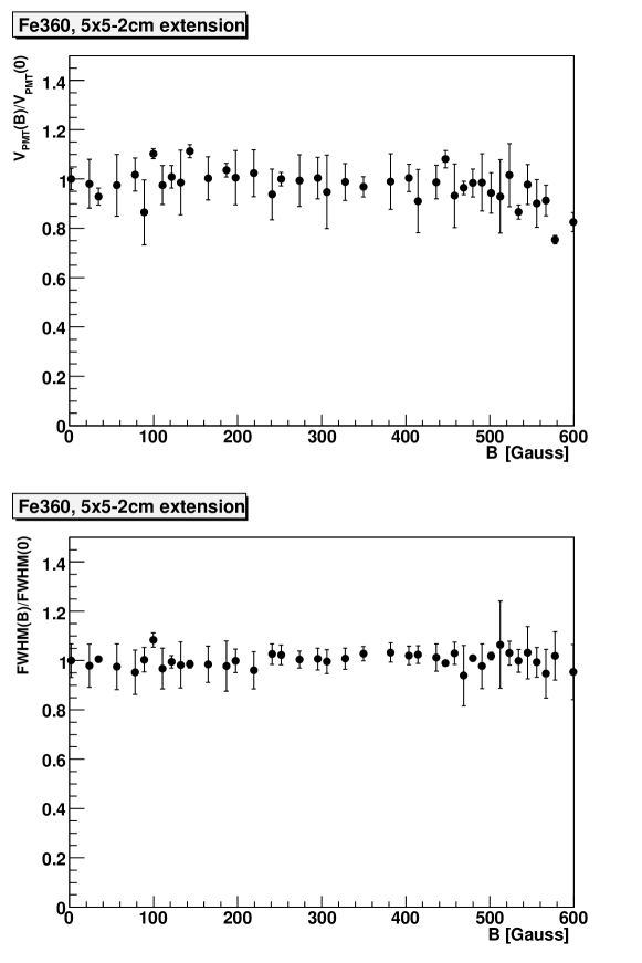
Figure 5 shows a comparison for the different box-shaped composite shieldings (signal reduction and timing versus the magnetic field intensity B) for the average and rms of a sample of ten R4998 PMTs. The shielding effect may be increased, by moving the PMT assembly more inside the shielding box, as shown in figures 6-7 for a 5x 5 cm Fe360 shielding, in addition to the metal one.
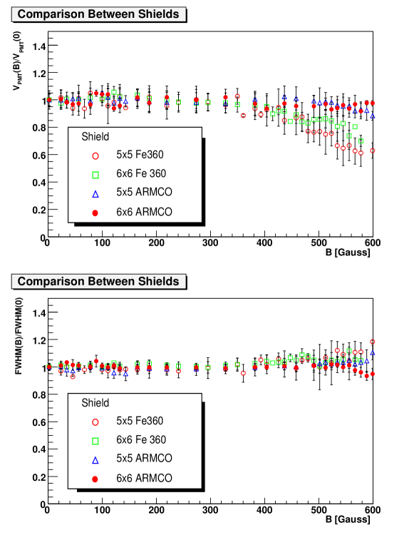
As a general conclusion, we see that:
-
1.
very low carbon content iron (ARMCO) is more effective than standard Fe360, even if this latter is acceptable for fields up to 500 G
-
2.
box-shaped soft iron shields are more effective than round-shaped ones of similar size
-
3.
as expected, more massive shieldings (from to transverse area) are better
-
4.
extending the external soft iron shielding beyond the -metal shielding improves the performance
The effectiveness of box-shaped iron shielding, in addition to -metal, for conventional PMTs has been tested also with other types of PMTs. The bottom panel of figure 4 shows the results for a typical Hamamatsu 1” R9800 conventional PMT, using a -metal shielding only and various types of soft iron (Fe360 or ARMCO) box shieldings. No deterioration in gain is seen up to Gauss for B∥ 121212R9800 PMTs may have a better behaviour with respect to R4998 PMTs, due their smaller size and the fewer number of stages, 8 against 10.
As long as the PMT signal amplitude has a sizeable pulse-height no deterioration in timing is seen. 131313only with the 1 mm thick -metal shielding or the 1 mm thick shielding + Fe360 box shielding some effect was evident in timing ( or its FWHM), at the level, when the signal amplitude experienced a reduction of a factor in one case or two in the other. As local shielding is mainly a mass effect we may expect an improvement if shieldings of individual PMTs are put in magnetic contact. This is clearly shown in figure 4 (top right-hand panel) where an additional iron box of similar shape is put in magnetic contact with the iron box shielding the PMT. This is the more common situation for detectors with an array of similar channels, where shielding may be improved by simply putting all soft iron individual external shields in magnetic contact.
The systematic uncertainties in our studies are coming mainly from:
-
1.
uniformity of the magnetic field ( better than 3%),
-
2.
stability of the laser pulse intensity (better than 2%),
-
3.
error in positioning of PMTs inside the magnetic field.
The simple mechanics of the system allowed a reproducibility of the positioning of the different PMTs’ at the level of some mm. Every single measurement referred to about 500-1000 events, giving a negligible statistical error as compared to systematics. From all the previous sources of errors, we may conservatively estimate a measurement error around .
No detailed study was done to assess possible azimuthal angle effects on the PMTs and hysteresis effects in the shielding.
As expected PMTs behave well for orientation of the B field orthogonal to the PMT axis (), where the shielding effect is maximal, while along the PMT axis () the gain reduction is more marked.
Conventional PMTs may be shielded effectively up to longitudinal fields Gauss, with simple composite shieldings using metal and soft iron box-shaped shields. For larger magnetic fields, fine-mesh PMTs may be a better option, even if some additional care must be taken for what regards their orientation with respect to the magnetic field (see next section for typical results).
3 Tests on fine-mesh PMTs
Systematic studies have been carried out also for 1” (R5505), 1.5” (R7761) and 2” (R5924) Hamamatsu fine-mesh PMTs (see table 1 for more details). They were delivered by Hamamatsu as assemblies with a resistive divider base and a 1 mm thick metal shielding, cut at the photocathode edge. A refurbished resistive dipole magnet at LASA (INFN Milano), with magnetic fields up to 1.2 T and an open gap of 12 cm, was used. The test setup was similar to the one employed for the tests of conventional PMTs, aside the use of a PLP-10 Hamamatsu laser 141414 Laser pulses at nm, with 60 ps FWHM pulse width and max repetition rate 100 MHz. Data were acquired, after a passive splitter, both for amplitude measurements (via a CAEN VME V465 QADC) and for timing measurements (via a CAEN VME V480 TDC, with a resolution of 25 ps/ch). The laser sync out, that had a maximum jitter of ps with respect to the optical pulse, provided in both cases the START/gate signal. Tests were usually done with a signal corresponding to about 300 photoelectrons (p.e.). The optical power was periodically monitored with an OPHIR PD-2A laser powermeter. The PMTs under test were inserted in the central region of the test magnet, where the field had a uniformity of , using plexiglass supports to incline them up to with respect to the B field lines.
Gain reduction and timing resolution were measured as a function of magnetic field and relative orientation angle () for the three types of fine-mesh PMTs under study. Due to the effect of magnetic field on the accelerated electrons inside the PMTs we can expect a reduction of gain as the B field increases and also a marked dependence of the relative gain as a function of the orientation angle. The gain reduction as a function of the increasing magnetic field at various values of are shown for typical 1”,1.5”,2” fine-mesh PMTs in figure 8 151515Results for the R5924 PMTs have been reported previously in reference [14].


A more detailed study of the effect of the PMT orientation with respect to the magnetic field was performed at moderate values of the magnetic field (up to Gauss) with the same setup used for the tests of conventional PMTs. Results for a typical 1” or 1.5” fine-mesh PMT are also reported in Figure 8. The decrease of the relative gain at large values of is connected to secondary electron losses: large angle electrons fall out the grid surfaces and are lost. The deflection of particle trajectories is also responsible for the enhancement of gain up to a certain value of . Fine-mesh PMTs are well behaving up to a critical orientation depending on the size of the projection of the photocathode onto the anode, with respect to the magnetic field direction: typically . For an orientation angle exceeding the critical angle the gain of a fine-mesh PMT has a noticeable decrease and shows a complicate behaviour, as the magnetic field B increases, up to values () beyond which the gain shows a steep drop in gain. This effect may be reduced by using a composite shielding solution similar to the one adopted for conventional PMTs.
Timing characteristics of fine-mesh PMTs show a weak dependence from the field strength and direction up to T, in spite of the large gain reduction, as also shown in figure 8 for .
4 Conclusions
Measurements have been performed up to longitudinal fields of 600 G for a sample of conventional R4998 PMTs, with different shielding options. While a simple 1-mm thick -metal shielding is satisfactory up to 60 (150) G for an axial (orthogonal) B field, an additional ARMCO () shield is required for longitudinal (orthogonal) fields up to 600 G.
Additional measurements for fine-mesh PMTs in magnetic fields up to 1.2 T (see [15] for additional details) show that fine-mesh PMTs are insensitive to longitudinal magnetic fields up to T. However their performance degrades quickly for orientation angles larger than a critical value (), even at small values of the magnetic field. This critical angle is typically in the range .
The previous results may be of interest for the optimization of time-of-flight detectors, based on scintillation counters read by PMTs, that have to work inside moderate magnetic field or the fringe fields of high magnetic fields. TOF detector timing resolutions show comparable results with both conventional R4998 PMTs or fine-mesh R5505 PMTs, see reference [6] for more details.
Acknowledgments
The essential help of Dr. Y. Karadzhov (University of Sofia), Dr. M. Rayner (University of Oxford) and Dr. G. Cecchet (INFN Pavia) in the setting up of the data taking and the early stages of this work is acknowledged. We would like to thank Dr. L. Tortora (INFN Roma Tre) who raised our attention to the D0 note on the conventional PMT box shielding. We acknowledge the help of Mr. F. Chignoli and R. Mazza of INFN Milano Bicocca for the preparation of the mechanics setup. We are indebted also to Dr. M. Bombonati and L. Confalonieri, Hamamatsu Italia, and Ing. L. Vernocchi for help and many enlightening discussions.
References
- [1] W.B. Atwood, Lecture at SLAC Summer Institute, 1980, p. 287.
- [2] M. Bonesini,“A Review of Recent Techniques of Tof Detectors”, 8th ICATPP Conference, Villa Olmo, conf. proceedings, 2003.
-
[3]
S.O.Flyckt, C. Marmorier “Photomultiplier Tubes,
principles and applications”, Photonis, 2002;
Hamamatsu Photonics K.K., “ Photomultiplier Tubes, Basics and Applications”, 3rd Edition, 2006;
R.Rikitake, “Magnetic and electromagnetic shielding”, Terra Scientific Publishing, Tokyo, 1988. - [4] M. De Gerone et al., “Development and commissioning of the Timing Counter for the MEG experiment”, preprint arXiv:1112.0110, 2011.
- [5] J. Adam et al. “A limit for the decay from the MEG experiment”, Nucl. Phys. B834 (2010) 1.
- [6] R. Bertoni et al. “The design and commissioning of the MICE upstream time-of-flight system”, Nucl. Instr. Meth. A615 (2010) 14.
- [7] M.Bonesini, “The MICE beamline instrumentation for a precise emittance measurement ”, PoS EPS-HEP2011 (2011) 197.
- [8] A. Blondel et al. “Proposal to the Rutherford Appleton Laboratory: an international muon ionization cooling experiment (MICE)”, 2003.
-
[9]
M. Alsharo’a et al., “Recent progress in neutrino
factory and muon collider research within the Muon collaboration”,
Phys. ReV. ST Accel. Beams 6 (2003) 081001;
M. Bonesini and A Guglielmi, Phys. Rep. 433 (2006) 65. - [10] D.Neuffer, “Multi-TeV muon colliders”, AIP Conf. Proc. 156 (1987) 201.
- [11] FEMM 4.2 program; http://www.fem.info
- [12] R. Stephens et al., D0 Note 2706, 1996.
-
[13]
M. Bonesini et al., IEEE Trans. Nucl. Science 50 (2003) 541;
M. Baldo-Ceolin et al., “ The time-of-flight TOFW detector of the HARP experiment: construction and performances”, Nucl. Instr. Meth. A532 (2004) 548. - [14] T.Iijima et al., “Study of fine-mesh PMTs for detection of aereogel Cherenkov light”, Nucl. Instr. Meth. A387 (1997) 64.
- [15] M. Bonesini et al. “Behaviour in high magnetic fields of fine-mesh photodetectors for fast time-of-flight detectors”, Nucl. Instr. Meth. A567 (2006) 200.