Rapid Coagulation of Porous Dust Aggregates Outside the Snow Line: A Pathway to Successful Icy Planetesimal Formation
Abstract
Rapid orbital drift of macroscopic dust particles is one of the major obstacles against planetesimal formation in protoplanetary disks. We reexamine this problem by considering porosity evolution of dust aggregates. We apply a porosity model based on recent -body simulations of aggregate collisions, which allows us to study the porosity change upon collision for a wide range of impact energies. As a first step, we neglect collisional fragmentation and instead focus on dust evolution outside the snow line, where the fragmentation has been suggested to be less significant than inside the snow line because of a high sticking efficiency of icy particles. We show that dust particles can evolve into highly porous aggregates (with internal densities of much less than ) even if collisional compression is taken into account. We also show that the high porosity triggers significant acceleration in collisional growth. This acceleration is a natural consequence of particles’ aerodynamical property at low Knudsen numbers, i.e., at particle radii larger than the mean free path of the gas molecules. Thanks to this rapid growth, the highly porous aggregates are found to overcome the radial drift barrier at orbital radii less than 10 AU (assuming the minimum-mass solar nebula model). This suggests that, if collisional fragmentation is truly insignificant, formation of icy planetesimals is possible via direct collisional growth of submicron-sized icy particles.
Subject headings:
dust, extinction — planets and satellites: formation — protoplanetary disks1. Introduction
Growth of dust particles is a key process in protoplanetary disks. Current theories of planet formation assume kilometer-sized solid bodies called “planetesimals” to form from dust contained in protoplanetary disks. Being the dominant component of disk opacity, dust also affects the temperature and observational appearance of the disks. Furthermore, dust particles are known to efficiently capture ionized gas particles in the gas disk, thereby controlling magnetohydrodynamical behaviors of it (Sano et al., 2000).
Theoretically, however, it is poorly understood how the dust particles evolve into planetesimals. One of the most serious obstacles is the radial inward drift of macroscopic aggregates due to the gas drag (Whipple, 1972; Adachi et al., 1976; Weidenschilling, 1977). Because of the gas pressure support in addition to the centrifugal force, protoplanetary disks tend to rotate at sub-Keplerian velocities. By contrast, dust particles are free from the pressure support, and hence they tend to rotate faster than the gas disk. The resulting head wind acting on the dust particles extracts their angular momentum and thus causes their drift motion toward the central star. In order to go beyond this “radial drift barrier,” dust particles must decouple from the gas drag (i.e., grow large) faster than they drift inward. However, previous work by Brauer et al. (2008a) showed that dust particles finally fall onto the central star unless the initial dust-to-gas mass ratio is considerably higher than the canonical interstellar value.
Several mechanisms have been raised so far regarding how dust particles overcome the radial drift barrier. A classical idea is that dust particles “jump” across the barrier by forming a gravitationally unstable thin dust layer at the midplane and directly collapsing into planetesimal-size objects (Safronov, 1969; Goldreich & Ward, 1973; Hayashi et al., 1985). However, this classical scenario has been challenged by the fact that the dust layers are easily stirred up by disk turbulence (Weidenschilling & Cuzzi, 1993; Turner et al., 2010). Moreover, the dust sublayer is known to induce the Kelvin-Helmholtz instability, which prevents further sedimentation of dust even without disk turbulence unless the dust-to-gas surface density ratio is considerably high (Sekiya, 1998). Recently, a two-fluid instability of dust and gas has been discovered (Youdin & Goodman, 2005), which can lead to fast formation of gravitationally bound dust clumps (e.g., Johansen & Youdin, 2007; Johansen et al., 2007; Bai & Stone, 2010a). However, this mechanism requires marginally decoupled dust particles, the formation of which is already questioned by the radial drift barrier itself. Other possibilities include the trapping of dust particles in vortices (e.g., Barge & Sommeria, 1995; Klahr & Henning, 1997) and at gas pressure maxima (e.g., Kretke & Lin, 2007; Brauer et al., 2008b; Suzuki et al., 2010; Pinilla et al., 2012).
This study reexamines this problem by considering a new physical effect: porosity evolution of dust aggregates. Most previous coagulation models (e.g., Nakagawa et al., 1981; Tanaka et al., 2005; Brauer et al., 2008a; Birnstiel et al., 2010) assumed that dust particles grow with a fixed internal density. In reality, however, the internal density of aggregates does change upon collision depending on the impact energy. The evolution of porosity directly affects the growth history of the aggregates since the porosity determines the coupling of them to the gas motion. For example, Ormel et al. (2007) and Zsom et al. (2011) simulated dust growth with porosity evolution at fixed disk orbital radii and found that porous evolution delays the settling of dust onto the disk midplane. However, how the porosity evolution affects the radial drift barrier has been unaddressed so far.
It has been studied over last two decades how the internal structure changes upon collision by laboratory (e.g., Blum & Wurm, 2000; Weidling et al., 2009) and numerical (e.g., Dominik & Tielens, 1997; Wada et al., 2008; Suyama et al., 2008, 2012) collision experiments. One robust finding of these studies is that aggregates grow into low-density, fractal objects if the impact energy is lower than a threshold determined by material properties (Blum & Wurm, 2000; Suyama et al., 2008; Okuzumi et al., 2009). The fractal dimension of the resulting aggregates depends weakly on the size ratio between targets and projectiles, and falls below two when the target and projectile have similar sizes (Mukai et al., 1992; Okuzumi et al., 2009). The fractal dimension of two is equivalent to an internal density decreasing inversely proportional to the aggregate radius. The density decrease occurs because each merger event involves the creation of “voids” whose volume is comparable to those of the aggregates before merger (Okuzumi et al., 2009). Suyama et al. (2008) estimated the collision energy of aggregates in protoplanetary disks as a function of size, and showed that aggregates composed of sized particles undergo fractal growth in planet-forming regions until their size reaches centimeters. This means that the building blocks of planetesimals should have once evolved into very fluffy objects with mean internal densities many orders of magnitude lower than the solid material density.
More strikingly, recent -body experiments suggest that the porosity of aggregates can be kept considerably high even after the collision energy exceeds the threshold . Wada et al. (2008) numerically simulated head-on collisions between equal-sized fractal aggregates of and found that the fractal dimension after the collision does not exceed even at high collision energies. Suyama et al. (2008) confirmed this by repeating head-on collisions of the resulting aggregates at fixed collision velocities. Furthermore, compaction is even less efficient in offset collisions, where the collision energy is spent for stretching rather than compaction of the merged aggregate (Wada et al., 2007; Paszun & Dominik, 2009). These results mean that the creation of voids upon merger is nonnegligible even when the impact energy is large; in other words, the voids are only imperfectly crushed in collisional compaction. Because of technical difficulty, these theoretical predictions have not yet been well tested by laboratory nor microgravity experiments. Nevertheless, it is worth investigating how aggregates grow and drift inward if they evolve into highly porous objects.
In this study, we simulate the temporal evolution of the radial size distribution of aggregates using the advection–coagulation model developed by Brauer et al. (2008a). Unlike the previous work, we allow the porosities of aggregates to change upon collision, depending on their impact energies. To do so, we adopt the “volume-averaging method” proposed by Okuzumi et al. (2009). In this method, aggregates of equal mass are regarded as having the same volume (or equivalently, the same internal density) at each orbital distance, and the advection–coagulation equation for the averaged volume is solved simultaneously with that for the radial size distribution. To determine the porosity change upon collisional sticking, we use an analytic recipe presented by Suyama et al. (2012) that well reproduces the collision outcomes of recent -body simulations (Wada et al., 2008; Suyama et al., 2008) as a function of the impact energy. These theoretical tools allow us to study for the first time how the porosity evolution affects the growth and radial drift of dust aggregates in protoplanetary disks.
In order to clarify the role of porosity evolution, we ignore many other effects relevant to aggregate collision, including Coulomb interaction (Okuzumi, 2009; Okuzumi et al., 2011a, b; Matthews et al., 2012), bouncing (Zsom et al., 2010, 2011; Windmark et al., 2012), and collisional fragmentation (Brauer et al., 2008a, b; Birnstiel et al., 2009, 2012). Coulomb repulsion due to negative charging can significantly slow down the initial fractal growth, but may be negligible once the collisional compaction becomes effective (Okuzumi et al., 2011b). Bouncing is often observed in laboratory experiments for relatively compact (filling factor ) aggregates, but is less likely to occur when aggregates are highly porous as we consider in this study (Langkowski et al., 2008; Wada et al., 2011). Seemingly more problematic is fragmentation at high-speed collisions. This is particularly so when the aggregates are mainly composed of silicate particles, for which catastrophic disruption begins at collision speeds as low as a few (Blum & Wurm, 2008; Wada et al., 2009; Güttler et al., 2010). By contrast, collisional fragmentation may be less problematic for aggregates made of icy particles, for which a higher sticking threshold has been anticipated (Chokshi et al., 1993; Dominik & Tielens, 1997; Gundlach et al., 2011). For instance, -body collision experiments by Wada et al. (2009) suggest that aggregates made of sized icy grains do not experience catastrophic disruption at collision velocities up to –. For this reason, instead of neglecting collisional fragmentation, we focus on dust evolution outside the snow line in protoplanetary disks. A more comprehensive model including the above mentioned effects will be presented in future work.
We will show that dust particles evolve into highly porous aggregates even if collisional compaction is taken into account. Furthermore, we will show that the porosity evolution triggers significant acceleration in collisional growth at early stages, allowing them to grow across the radial drift barrier in inner regions of protoplanetary disks. Interestingly, this acceleration involves neither enhancement of the collision velocity nor suppression of the radial drift speed of marginally decoupled aggregates. As we will see, this acceleration is a natural consequence of particles’ aerodynamical property at low Knudsen numbers, i.e., at particle radii larger than the mean free path of the gas molecules, and the porosity evolution only allows the dust aggregates to reach that stage with small aggregate masses. Our model calculation shows that the breakthrough of the radial drift barrier can occur in “planet-forming” regions, i.e., at from the central star. This result suggests that, if the fragmentation of icy aggregates is truly negligible, the formation of icy planetesimals is possible via direct collisional growth of dust particles even without an enhancement of the initial dust-to-gas mass ratio.
This paper is organized as follows. In Section 2, we describe the disk and collision models that we use in this study. Simulation results are presented in Section 3, which we interpret in terms of the timescales for collisional growth and radial inward drift in Section 4. The validity and limitations of our model are discussed in Section 5, and our conclusions are presented in Section 6.
2. Model
2.1. Disk Model
We adopt the minimum-mass solar nebula (MMSN) model of Hayashi (1981) with a solar-mass central star. The radial profiles of the gas surface density and disk temperature are given by and , respectively, where is the distance from the central star. In this study, we focus on dust evolution outside the snow line, which is located at in the adopted disk model. The vertical structure is assumed to be in hydrostatic equilibrium, and hence the vertical structure of the gas density is given by , where is the gas scale height, is the isothermal sound speed, and is the Kepler frequency. The isothermal sound speed is given by , where is the Boltzmann constant and is the mean molecular mass. We assume the mean molecular weight of 2.34, which gives and . The assumed stellar mass () leads to and , where is the gravitational constant.
In reality, protoplanetary disks can be heavier than the MMSN. The gravitational stability criterion (Toomre, 1964) allows the surface density to be up to about 10 times higher than the MMSN value. The dependence of our result on the disk mass will be analytically discussed in Section 4.
Initial dust particles are modeled as compact spheres of equal size and equal internal density , distributed in the disk with a constant dust-to-gas surface density ratio . The mass of each initial particle is . In the following, we will refer to the initial dust particles as “monomers.” We define the radius of a porous aggregate as , where is the number of the constituent monomers and is the position of the monomers (Mukai et al., 1992). This definition is in accordance with previous -body experiments (Wada et al., 2008; Suyama et al., 2008; Okuzumi et al., 2009) which our porosity model is based on (see Section 2.3.1).
Disk turbulence affects the collision and sedimentation of dust particles. To include these effects, we consider gas turbulence in which the turnover time and mean-squared random velocity of the largest turbulent eddies are given by and , respectively, where is the dimensionless parameter characterizing the strength of the turbulence. The assumption for is based on theoretical anticipation for turbulence in Keplerian disks (Dubrulle & Valdettaro, 1992; Fromang & Papaloizou, 2006; Johansen et al., 2006). The diffusion coefficient for the gas is given by . If the gas diffusion coefficient is of the same order as the turbulent viscosity, is equivalent to the so-called alpha parameter of Shakura & Sunyaev (1973). However, we do not consider the viscous evolution of the gas disk for simplicity. We adopt in our numerical simulations. A higher value of would cause catastrophic collisional fragmentation of aggregates, which is not considered in this study (see Section 5.3).
2.2. Evolutionary Equations
We solve the evolution of the radial size distribution of dust aggregates using the method developed by Brauer et al. (2008a). This method assumes the balance between sedimentation and turbulent diffusion of aggregates in the vertical direction. Thus, the vertical number density distribution of aggregates is given by a Gaussian , where is the column number density of aggregates per unit mass and is the scale height of aggregates at orbital radius and with mass (Dubrulle et al., 1995). This approach is valid if the coagulation timescale is longer than the settling/diffusion timescale, which is true except for very tiny particles with short collision times (Zsom et al., 2011).
The evolution of the radial size distribution is given by the vertically integrated advection–coagulation equation, which reads (Brauer et al., 2008a)
| (1) | |||||
where is the radial drift velocity and is the vertically integrated collision rate coefficient given by
| (2) |
Here, is the collisional cross section, and are the scale heights of the colliding aggregates 1 and 2, is the collision velocity, and . As mentioned in Section 1, we neglect electrostatic and gravitational interactions between colliding aggregates and assume perfect sticking upon collision. Thus, the collisional cross section is simply given by , where and are the radii of the colliding aggregates. The validity of neglecting fragmentation will be discussed in Section 5.3.
The dust scale height in sedimentation–diffusion equilibrium has been analytically obtained by Youdin & Lithwick (2007). For turbulence of and , it is given by
| (3) |
where is the stopping time of the aggregates. We use this expression in this study.
For the stopping time, we use
| (4) |
where and are the thermal velocity and mean free path of gas particles, respectively, and is the projected area of the aggregate. The mean free path is related to the gas density as
| (5) |
where is the collisional cross section of gas molecules. Our gas disk model gives at the midplane. Equation (4) satisfies the requirement that the stopping time must obey Epstein’s law at and Stokes’ law at , respectively. Since , an aggregate growing in the Stokes regime decouples from the gas motion more quickly than in the Epstein regime. In reality, Stokes’ law breaks down when the particle Reynolds number (the Reynolds number of flow around the particle) is much greater than unity, but we neglect this in our simulations for simplicity. We will discuss this point further in Section 5.1.
The radial drift velocity is taken as
| (6) |
where
| (7) |
is the ratio of the pressure gradient force to the stellar gravity in the radial direction and is the Kepler velocity (Adachi et al., 1976; Weidenschilling, 1977; Nakagawa et al., 1986). The radial drift speed has a maximum , which is realized when . In our disk model, scales with as , and the maximum inward speed is independent of . Since is proportional to the gas temperature, the maximum drift speed would be somewhat lower in colder disk models (Kusaka et al., 1970; Hirose & Turner, 2011). Equation (6) neglects the frictional backreaction from dust to gas assuming that the local dust-to-gas mass ratio is much lower than unity or the stopping time of aggregates dominating the dust mass is much longer than . We examine the validity of this assumption in Section 5.2.1.
In this paper, we also consider the collisional evolution of aggregate porosities. We treat the mean volume of aggregates with orbital radius and mass as a time-dependent quantity. The evolutionary equation for is given by
| (8) | |||||
where
| (9) |
with being the volume of merged aggregates (described in Section 2.3.1). Equation (8) is identical to the original evolutionary equation for derived by Okuzumi et al. (2009, their Equation (16)) except that we here take the vertical integration of the equation and take into account the radial advection of dust. In deriving Equation (8), we have assumed that the dispersion of the volume is sufficiently narrow at every and (see Okuzumi et al., 2009). This “volume-averaging” approximation allows to follow the porosity evolution of aggregates without solving higher-order moment equations for the volume, and hence with small computational costs. This approximation is valid unless the porosity distribution at fixed and is significantly broadened by, e.g., collisional fragmentation cascades (Okuzumi et al., 2009).
2.3. Dust Model
2.3.1 Porosity Change Recipe
The functional form of determines the evolution of aggregate porosities in our simulation. In this study, we give as a function of the volumes of the colliding aggregates, and , and the impact energy . Before introducing the final form of our porosity change recipe (Equation (15)), we briefly review recent -body collision experiments which our recipe is based on.
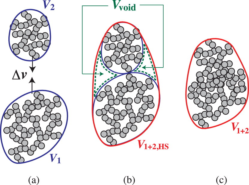
Collisional compression depends on the ratio between and the “rolling energy” (Dominik & Tielens, 1997; Blum & Wurm, 2000; Wada et al., 2007). The rolling energy is defined as the energy needed for one monomer to roll over on the surface of another monomer in contact (Dominik & Tielens, 1997). When , two aggregates stick without visible restructuring (so-called hit-and-stick collision; see Figure 1(b)). In this case, the volume of the merged aggregate is determined in a geometric manner, i.e., independently of . When , internal restructuring occurs through inelastic rolling among constituent monomers (Dominik & Tielens 1997; see also Figure 1(c)). In this case, the final volume depends on as well as on and .
For hit-and-stick collisions (), Okuzumi et al. (2009) obtained an empirical formula for ,
| (10) |
where and are the volumes of the two colliding aggregates, and
| (11) |
is the volume of the voids created in the collision (see Figure 1(b)). For , the void volume is approximately equal to , and hence the volume of the new aggregate is approximately given by . This is equivalent to a fractal relation , where (see Section 4.2.1 of Okuzumi et al., 2009).
In the limit of and for head-on collision of equal-sized aggregates (), Suyama et al. (2008) showed that obeys the relation
| (12) |
Here, is the dynamic compression strength of the merged aggregate given by (Wada et al., 2008)
| (13) |
where is a dimensionless fitting parameter, is the monomer volume, is the number of monomers contained in the merged aggregate, and is the internal density of the merged aggregate. If we substitute Equation (13) into Equation (12), we obtain the equation that explicitly gives as a function of and ,
| (14) |
This equation basically expresses the energy balance in collisional compression, but some caution is needed in interpreting it. First, the initial state for the compression is chosen to be , although the volume just after contact is (see above). This is based on the fact that compaction from to occurs through partial compression of the new voids, which requires little energy (Suyama et al., 2008). Second, the dynamic compression strength depends on mass as well as on internal density , meaning that is not an intensive variable. This is due to the fact that dynamically compressed parts in the merged aggregate have a fractal structure with the fractal dimension of (Wada et al., 2008). In fact, Equations (12)–(14) are more naturally described in terms of variables in the 2.5-dimensional space, , , and (see Wada et al., 2008; Suyama et al., 2008). An important point here is that aggregates become stronger and stronger against dynamic compression as they grow because of the factor in .
Equations (10) and (14) express how the volume of the merged aggregate is determined in the limits of and , respectively. To properly take into account intermediate cases (), we adopt an updated analytic formula given recently by Suyama et al. (2012). This reads
| (15) |
where is now defined as . Note that this equation reduces to Equations (10) when , and to Equation (14) when and . Suyama et al. (2012) derived Equation (15) by taking into account small energy loss in the partial compression of the new voids. In addition, unlike Equation (14), Equation (15) takes into account the cases where colliding aggregates have different volumes and masses (, ). Suyama et al. (2012) confirmed that Equation (15) reproduces the results of numerical collision experiments within an error of 20% as long as the mass ratio between the colliding aggregates is larger than 1/16.
We comment on three important caveats regarding our porosity recipe. First, Equation (15) is still untested for cases where colliding aggregates have very different sizes (). Therefore, the validity of using Equation (15) is at present only guaranteed for the case where “similar-sized” () collisions dominate the growth of aggregates. We will carefully check this validity in Section 3.2. Second, Equation (15) ignores offset collisions, in which a considerable fraction of the impact energy is spent for stretching rather than compaction (Wada et al., 2007; Paszun & Dominik, 2009). For this reason, Equation (15) underestimates the porosity increase upon collision. Third, we do not consider non-collisional compression (e.g., static compression due to gas drag forces), which could contribute to the compaction of very large aggregates. We will discuss the second and third points in more detail in Section 5.4.
In addition to , we need to know the projected area of aggregates to calculate the stopping time . Unfortunately, a naive relation breaks down when the fractal dimension of the aggregate is less than 2, since increases faster than mass for this case while does not. A projected area growing faster than mass means a coupling to the gas becoming stronger and stronger as the aggregate grows, which is clearly unrealistic. To avoid this, we use an empirical formula by Okuzumi et al. (2009) that well reproduces the mean projected area of aggregates with monomer number and radius for both fractal and compact aggregates. With this formula, all aggregates in our simulations are guaranteed to decouple from the gas as they grow. We remark that this treatment is only relevant to fractal aggregates with ; for more compact aggregates, the empirical formula reduces to the usual relation .
The rolling energy has not been measured so far for submicron-sized icy particles, but can be estimated in the following way. It is anticipated by microscopic friction theory (Dominik & Tielens, 1995) that the critical rolling force is a material constant (i.e., is proportional to the monomer radius ). Recently, a rolling force of has been measured for micron-sized ice particles (Gundlach et al., 2011). Given that is independent of , the measured force implies the rolling energy of for . We use this value in our simulations.
2.3.2 Collision Velocity
We consider Brownian motion, radial and azimuthal drift, vertical settling, and turbulence as sources of the collision velocity, and give the collision velocity as the root sum square of these contributions,
| (16) |
where , , , , and are the relative velocities induced by Brownian motion, radial drift, azimuthal drift, vertical settling, and turbulence, respectively.
The Brownian-motion-induced velocity is given by
| (17) |
where and are the masses of the two colliding aggregates.
The relative velocity due to radial drift is given by , where and are the stopping times of the colliding aggregates, and is the radial velocity given by Equation (6). Similarly, the relative velocity due to differential azimuthal motion is given by , where
| (18) |
is the deviation of the azimuthal velocity from the local Kepler velocity (Adachi et al., 1976; Weidenschilling, 1977; Nakagawa et al., 1986). Here, we have neglected the backreaction from dust to gas as we already did for the radial velocity (see Sections 2.3.2 and 5.2.1).
For the differential settling velocity, we assume , where
| (19) |
Equation (19) reduces to the terminal settling velocity in the strong coupling limit , and to the amplitude of the vertical oscillation velocity at (Brauer et al., 2008a).
For the turbulence-driven relative velocity, we use an analytic formula for Kolmogorov turbulence derived by Ormel & Cuzzi (2007, their Equation (16)). This analytic formula has three limiting expressions (Equations (27)–(29) of Ormel & Cuzzi 2007):
| (20) |
where is the turbulent Reynolds number, is the turnover time of the smallest eddies, and the numerical prefactor in the second equality depends on the ratio between the stopping times, . The turbulent Reynolds number is given by , where is the molecular viscosity. For , the maximum induced velocity is , which is reached when .
When two colliding aggregates belong to the Epstein regime and their stopping times are much shorter than , the relative velocity driven by sedimentation and turbulence is approximately proportional to the difference between the mass-to-area ratios of two colliding aggregates. In this case, as pointed out by Okuzumi et al. (2011a), the dispersion of the mass-to-area ratio becomes important for fractal aggregates of , since the mean mass-to-area ratio of the aggregates approaches to a constant and hence the difference in vanishes. To take into account the dispersion effect, we evaluate the differential mass-to-area ratio as , where are the mean projected area of aggregates with mass (see Section 2.3.1) and is the standard deviation of the mass-to-area ratio divided by the mean (for the derivation, see the Appendix of Okuzumi et al., 2011a). We assume in accordance with the numerical estimate by Okuzumi et al. (2011a).
2.4. Numerical Method
We solve Equations (1) and (8) numerically with an explicit time-integration scheme and a fixed-bin method. The radial domain is taken to be outside the snow line, , discretized into 100 rings with an equal logarithmic width . The advection terms are calculated by the spatially first-order upwind scheme. We impose the outflow and zero-flux boundary conditions at the innermost and outermost radii ( and 150 AU), respectively; thus, the total dust mass inside the domain is a decreasing function of time. Our numerical results are unaffected by the choice of the boundary condition at the outermost radius, since dust growth at this location is too slow to cause appreciable radial drift within the calculated time. The coagulation terms are calculated by the method given by Okuzumi et al. (2009). Specifically, at the center of each radial ring we divide the mass coordinate into linearly spaced bins for and logarithmically spaced bins for , where is an integer. We adopt ; as shown by Okuzumi et al. (2009), the calculation results well converge as long as . The time increment is adjusted at every time step so that the fractional decreases in and fall below 0.5 (i.e., and ) at all bins.
3. Results
3.1. Compact Aggregation
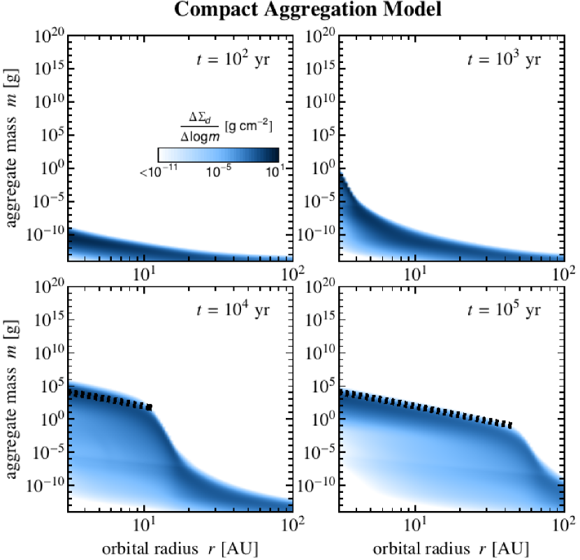

To begin with, we show the result of compact aggregation. In this simulation, we fixed the internal density of the aggregates to the material density , and solved only the evolutionary equation for the radial size distribution (Equation (1)), as done in previous studies (e.g., Brauer et al., 2008a). Figure 2 shows the snapshots of the radial size distribution at different times. Here, the distribution is represented by the dust surface density per decade of aggregate mass, . At each orbital radius, dust growth proceeds without significant radial drift until the stopping time of the aggregates reaches (the dotted lines in Figure 2). However, as the aggregates grow, the radial drift becomes faster and faster, and further growth becomes limited only along the line on the – plane. Figure 3 shows the evolution of the total dust surface density . We see that a significant amount of dust has been lost from the planet-forming region within . In this region, the dust surface density scales as 111 It can be analytically shown (Birnstiel et al., 2012) that the dust surface density profile obeys a scaling ( for ) when radial drift balances with turbulence-driven growth. and hence the dust-to-gas surface density ratio decreases toward the central star.
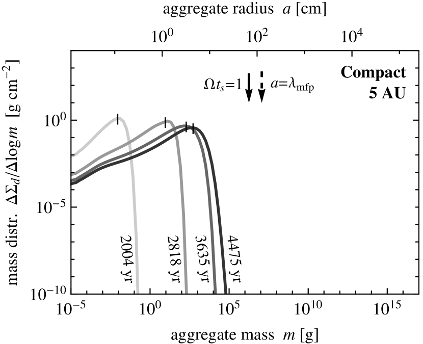
Figure 4 shows the evolution of the dust size distribution observed at . Here, in order to characterize the typical aggregate size at each evolutionary stage, we introduce the weighted average mass defined by
| (21) |
The weighted average mass approximately corresponds to the aggregate mass at the peak of (see, e.g., Ormel et al., 2007; Okuzumi et al., 2011a). In Figure 4, the weighted average mass at each time is indicated by the short vertical line. At , the growth–drift equilibrium is reached at , and the typical size of the aggregates is in mass ( cm in radius, in stopping time). Note that the final aggregate radius is much smaller than the mean free path of gas molecules (the dashed arrow in Figure 4), which means that the gas drag onto the aggregates is determined by Epstein’s law. As we will see in the following, porosity evolution allows aggregates to reach the Stokes drag regime at much smaller .
3.2. Porous Aggregation
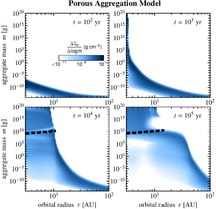
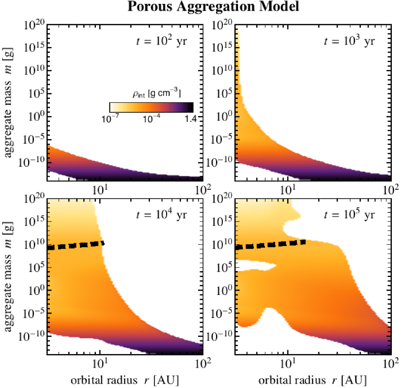
Now we show how porosity evolution affects dust evolution. Here, we solve the evolutionary equation for (Equation (8)) simultaneously with that for (Equation (1)). The result is shown in Figure 5, which displays the snapshots of the aggregate size distribution and internal density at different times as a function of and . The evolution of the total dust surface density is shown in Figure 6.
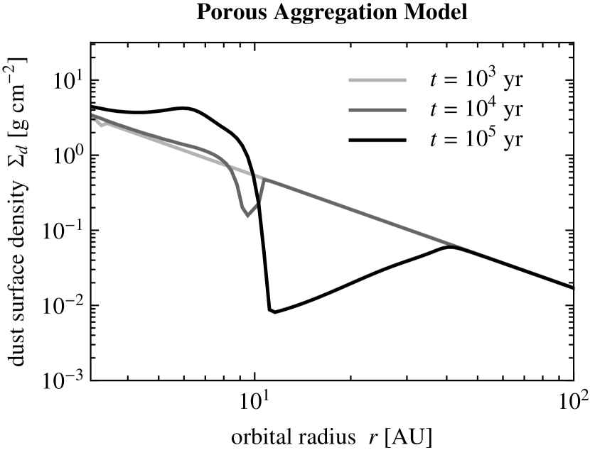
The left four panels of Figure 5 show how the radial size distribution evolves in the porous aggregation. At , the evolution is qualitatively similar to that in compact aggregation (Section 3.1). However, in later stages, the evolution is significantly different. We observe that aggregates in the inner region of the disk () undergo rapid growth and eventually overcome the radial drift barrier lying at (dashed lines in Figure 5) within . At this stage, the radial profile of the total dust surface is hardly changed from the initial profile, as is seen in Figure 6. In the outer region (), aggregates do drift inward before they reach as in the compact aggregation model. However, unlike in the compact aggregation, the inward drift results in the pileup of dust materials in the inner region (–) rather than the loss of them from outside the snow line (see Figure 6). This occurs because most of the drifting aggregates get captured by aggregates that have already overcome the drift barrier. As a result of this, the dust-to-gas mass ratio in the inner regions is enhanced by a factor of several in .
The right four panels of Figure 5 show the evolution of the internal density as a function of and . First thing to note is that the dust particles grow into low-density objects at every location until their internal density reaches –. In this stage, the internal density decreases as , meaning that the dust particles grow into fractal aggregates with the fractal dimension (Okuzumi et al., 2009). The fractal growth generally occurs in early growth stages where the impact energy is too low to cause collisional compression, i.e., (e.g., Blum, 2004; Ormel et al., 2007; Zsom et al., 2010). At –, the fractal growth stage terminates, followed by the stage where collisional compression becomes effective (). In this late stage, the internal density decreases more slowly or is kept at a constant value depending on the orbital radius. We will examine the density evolution in more detail in Section 3.2.2.
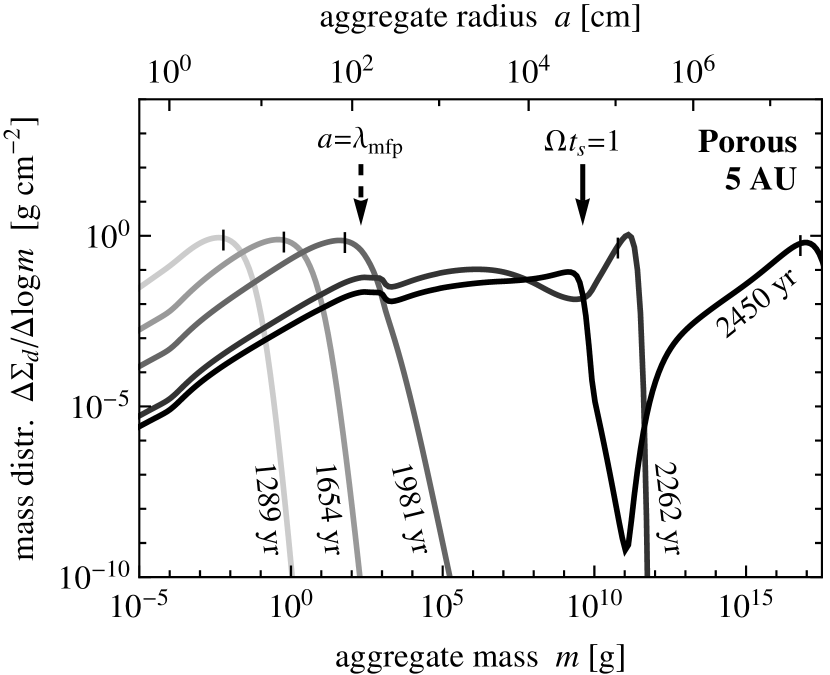

Figure 7 shows the evolution of the mass distribution function at during –. The evolution of the weighted average mass is shown in Figure 8. It is seen that the acceleration of the growth begins when the aggregate size exceeds the mean free path of gas molecules, (the dashed arrow in Figure 7). This suggests that the acceleration is due to the change in the aerodynamical property of the aggregates. At , the gas drag onto the aggregates begins to obey Stokes’ law. In the Stokes regime, the stopping time of aggregates quickly increases with size (see Section 2.2). This causes the quick growth of the aggregates since the relative velocity between aggregates increases with (as long as ). As a result of the growth acceleration, the aggregates grow from to within , which is short enough for them to break through the radial drift barrier.
The decrease in the internal density plays an important role on the growth acceleration. More precisely, the low internal density allows the aggregates to reach at early growth stages, i.e., at small . In fact, the growth acceleration was not observed in the compact aggregation, since the aggregate size is smaller than the mean free path at all (see Figure 4). A more rigorous explanation for this will be given in Section 4.
3.2.1 Projectile Mass Distribution
As noted in Section 2.3.1, our porosity change model has only been tested for collisions between similar-sized aggregates. To check the validity of using this model, we introduce the projectile mass distribution function (Okuzumi et al., 2009):
| (22) |
which is normalized so that . The denominator of is equal to the growth rate of a target having mass (see Okuzumi et al., 2009). Hence, the quantity measures the contribution of projectiles within mass range to the growth of the target.
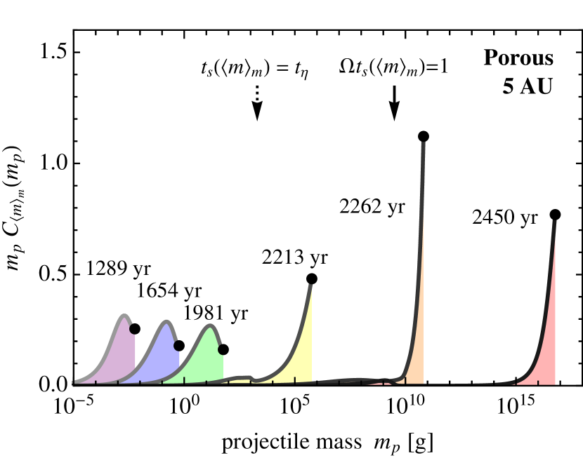
Figure 9 shows the projectile mass distribution per unit , , for targets with mass at and at different . We see that the growth of the target is dominated by projectiles within a mass range . In fact, the projectile mass distribution integrated over exceeds 50% for all the cases presented in Figure 9. This means that the growth of aggregates is indeed dominated by collisions with similar-sized ones as required by the limitation of our porosity model. This is basically the consequence of the fact that the aggregate mass distribution is peaked around the target mass (see Figure 7). The mass ratio at the peak of reflects the size dependence of the turbulence-driven relative velocity , which is the main source of the collision velocity in our simulation. At (), the dominant projectile mass is lower than , since both the target and projectiles are tightly coupled to turbulence (i.e., ) and hence vanishes at equal-sized collisions (see the first expression of Equation (20)). At (), the target decouples from small turbulent eddies (). This results in the shift of the dominant collision mode to because no more vanishes at equal-sized collisions (see the second line of Equation (20)).
3.2.2 Density Evolution History
To see the density evolution history in detail, we plot in Figure 10 the temporal evolution of the weighted average mass and the internal density of aggregates with mass at orbital radii and .
As mentioned above, dust particles initially grow into fractal aggregates of until the impact energy becomes comparable to the rolling energy . With this fact, one can analytically estimate the aggregate size at which the fractal growth terminates. Our simulation shows that the collision velocity between the fractal aggregates is approximately given by the turbulence-driven velocity in the strong-coupling limit (Equation (20) with ). Assuming that the collisions mainly occur between aggregates of similar sizes (see Section 3.2.1), the reduced mass and the collision velocity are roughly given by and , respectively. In addition, we use the fact that fractal aggregates with have the mass-to-area ratio comparable to their constituent monomers. This means that the stopping time of the aggregates is as short as the monomers and is hence given by Epstein’s law. Thus, the impact energy is approximated as
| (23) |
Furthermore, using the definitions for , , and , we have and for the midplane. Substituting them into Equation (23) and using and , we obtain
| (24) |
Thus, the impact energy is proportional to the mass. We define the rolling mass by the condition . Using Equation (24), the rolling mass is evaluated as
| (25) | |||||
where we have used that (see Section 2.3.1). Using the relations and for aggregates, the corresponding radius and internal density are found to be
| (26) |
| (27) |
The triangles in Figure 10 mark the rolling mass at and 20 AU predicted by Equation (25). The analytic prediction well explains when the decrease in terminates.
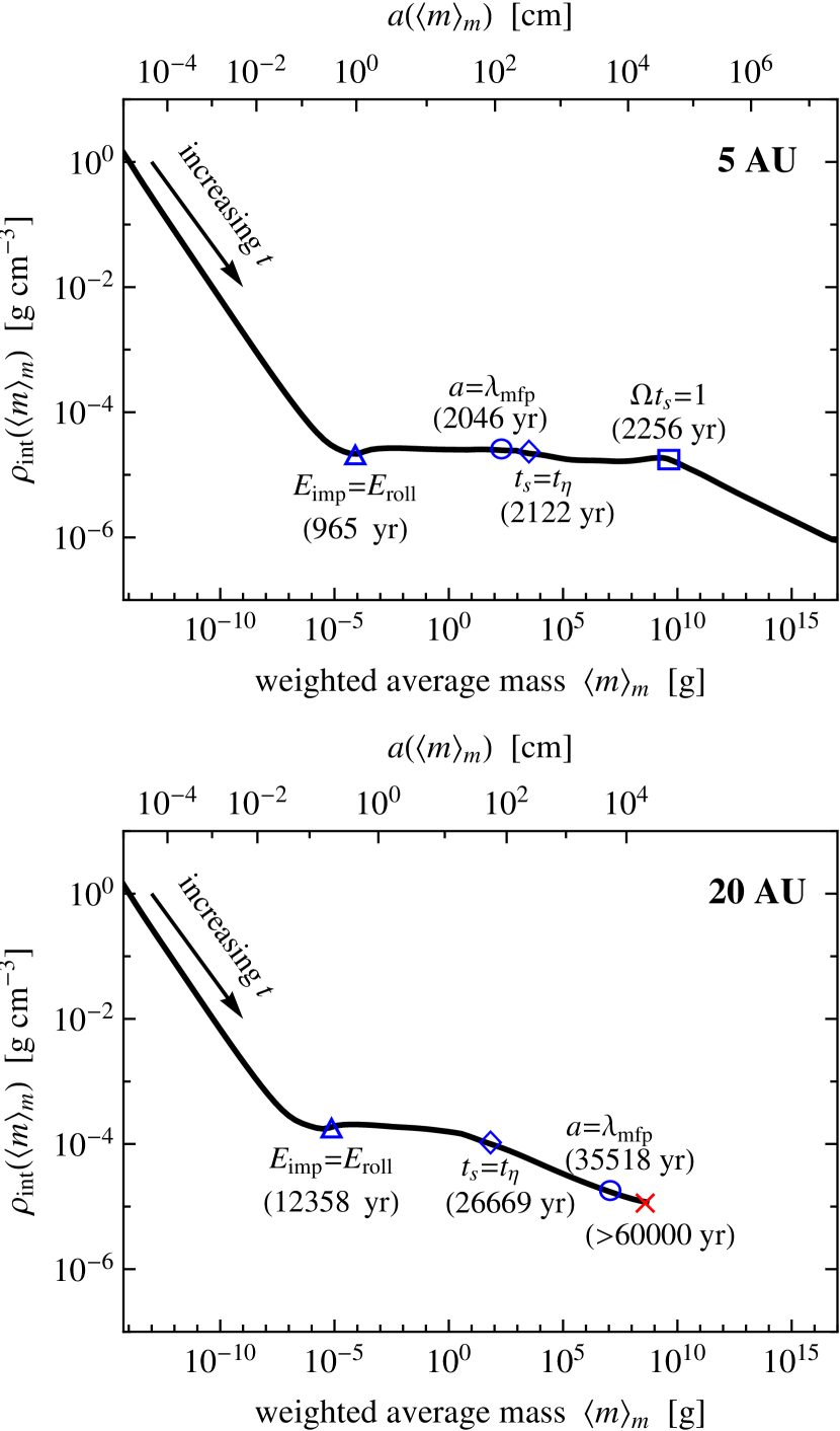
The density evolution is more complicated at , where collisional compression is no longer negligible (i.e., ). At , the internal density is approximately constant until the stopping time reaches , and then decreases as . At , by contrast, the density is kept nearly constant until (), and then decreases as .
As shown below, the density histories mentioned above can be directly derived from the porosity change recipe we adopted. Let us assume again that aggregates grow mainly through collisions with similar-sized ones ( and ). In this case, the evolution of at is approximately given by Equation (14). Furthermore, we neglect the term in Equation (14) assuming that the impact energy is sufficiently large (which is true as long as ; see below). Under these assumptions, the internal density of aggregates after collision, , is approximately given by
| (28) |
where . Since the impact energy is proportional to , Equation (28) implies that
| (29) |
where we have dropped the subscript for mass for clarity. Equation (29) gives the relation between and if we know how the impact velocity depends on them. Explicitly, if , Equation (29) leads to
| (30) |
In our simulation, the main source of the relative velocity is turbulence. The turbulence-driven velocity depends on as at and at (see Equation (20)). As found from Equation (4), the stopping time depends on and as in the Epstein regime () and as in the Stokes regime (). Using these relations with Equation (30), we find four regimes for density evolution,
| (31) |
The circles, diamonds, and square in Figure 10 mark the size at which (i.e., ), , and , respectively. At , the sizes at which and nearly overlap, and hence only two velocity regimes and are effectively relevant. For both cases, Equation (31) predicts flat density evolution. At , there is a stage in which and , for which Equation (31) predicts . These predictions are in agreement with what we see in Figure 10.
Equation (28) does not apply to the density evolution at , where the collision velocity no more increases and hence collisional compression becomes less and less efficient as the aggregates grow. However, if we go back to Equation (14) and assume that the impact energy is sufficiently small, we obtain , or equivalently , where is the aggregate mass after a collision. This implies that is kept constant during the growth, i.e., , and hence we have . This is consistent with the density evolution at seen in the upper panel of Figure 10.
4. Condition for Breaking Through the Radial Drift Barrier
In this section, we explain why porous aggregates overcome the radial drift barrier in the inner region of the disk. We do this by comparing the timescale of aggregate growth and radial drift. We assume that dust aggregates grow mainly through collisions with similar-sized aggregates. As shown in Section 3.2.1, this is a good approximation for the growth of aggregates dominating the total mass of the system (i.e., aggregates with mass ). The growth rate of the aggregate mass at the midplane is then given by
| (32) |
where is the spatial dust density at the midplane, and we have approximated as the projected area . Equation (32) can be rewritten in terms of the growth timescale as
| (33) |
where we have used that and . What we do here is to compare with the timescale for the radial drift given by
| (34) |
Now we focus on the stage at which the radial drift velocity reaches the maximum value, i.e., . At this stage, the dust scale height is given by according to Equation (3). In addition, we set since the collision velocity between particles is dominated by the turbulence-driven velocity. Using these relations and , we can rewrite Equation (33) as
| (35) | |||||
where is the Keplerian orbital period. Thus, the growth timescale is shorter when the mass-to-area ratio is smaller. Note that is independent of since both and scale with . By contrast, the drift timescale for particles is
| (36) |
The ratio of the two timescales is
| (37) | |||||
The ratio determines the fate of dust growth at . If is very small, dust particles grow beyond without experiencing significant radial drift; otherwise, dust particles drift inward before they grow. We expect growth without significant drift to occur if
| (38) |
where the threshold value takes into account the fact that is the timescale for mass doubling while the particles experience the fastest radial drift over decades in mass. Below, we examine in what condition this requirement is satisfied.
The ratio depends on the drag regime at . We consider the Epstein regime first. Using and , one can rewrite Epstein’s law as . Thus, for , we have a surprisingly simple relation
| (39) |
Inserting this relation into Equation (35), we obtain
| (40) |
Hence, the growth condition (Equation (38)) is not satisfied for the standard disk parameters and , in agreement with the results of our and previous (Brauer et al., 2008a) simulations. Note that the right-hand side of Equation (40) is independent of . Thus, the porosity of aggregates has no effect on the radial drift barrier within the Epstein regime.
The situation differs in the Stokes drag regime. A similar calculation as above leads to
| (41) |
and
| (42) |
Note that the growth timescale is inversely proportional to the aggregate radius, in contrast to that in the Epstein regime (Equation (40)) being independent of aggregate properties. Substituting Equations (36) and (42) into the growth condition (Equation (38)), we find that aggregates break through the radial drift barrier in the “deep” Stokes regime, . Unlike Equation (40), Equation (42) implicitly depends on through (see below), so the porosity of aggregates does affect the growth timescale in this case. It is interesting to note that the speedup of dust growth occurs even though the maximum collision velocity is the same. Indeed, the collision velocity depends only on and is thus independent of the drag regime. We remark that Stokes’ law breaks down when becomes so large that the particle Reynolds number becomes much larger than unity, as already mentioned in Section 2.2. We will show in Section 5.1 that this fact sets the minimum value of to ; see Equation (47).
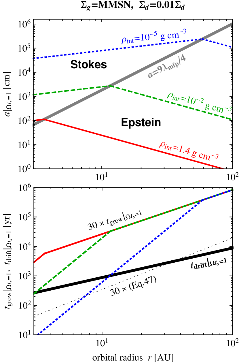
The internal density of aggregates controls the growth timescale through the aggregate size at . For given , one can analytically calculate from Equations (39) and (41). Explicitly,
| (43) |
for the Epstein regime, and
| (44) |
for the Stokes regime, where we have used and . For fixed , decreases with increasing in the Epstein regime, but increases in the Stokes regime. The upper panel of Figure 11 plots for three different values of the aggregate internal density . If dust particles grew into compact spheres (), Epstein’s law governs the motion of particles in almost entire parts of the snow region (). However, if dust particles grow into highly porous aggregates with , the particles growing at enter the Stokes regime before reaches unity. The lower panel of Figure 11 shows the two timescales and as calculated from Equations (35) and (36), respectively. We see that compact particles with do not satisfy the growth condition (Equation (38)) outside the snow line, while porous aggregates with do in the region . These explain our simulation results presented in Section 3.
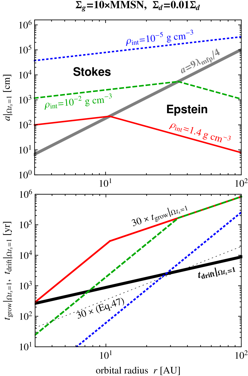
Finally, we remark that a high disk mass (i.e., a high with fixed ) favors the breakthrough of the radial drift barrier. Figure 12 shows the size and the timescales and at for a disk 10 times heavier than the MMSN. We see that the growth condition (Equation (38)) is now satisfied at for and at even for . This is because a higher leads to a shorter and hence allows aggregates to reach the Stokes regime at larger or with higher (note that enhancement of by a constant remains and hence unchanged). Interestingly, our porosity model predicts that is independent of . In fact, substituting Equation (44) with and into Equation (28), we obtain the equation for that does not involve .
5. Discussion
So far we have shown that the evolution of dust into highly porous aggregates is a key to overcome the radial drift barrier. On the other hand, in order to clarify the role of porosity evolution, we have ignored many other effects relevant to dust growth in protoplanetary disks. In this section, we discuss how the ignored effects would affect dust evolution.
5.1. Effect of the Friction Law at High Particle Reynolds Numbers
In this study, we have assumed that the stopping time obeys Stokes’ law whenever . In reality, Stokes’ law applies only when the particle Reynolds number (the Reynolds number of the gas flow around the particle) is less than unity, where is the gas–dust relative velocity. When , i.e., the particle becomes so large and/or the gas–dust relative velocity becomes so high, the stopping time becomes dependent on the particle velocity (see, e.g., Weidenschilling, 1977). In this subsection, we discuss how this effect affects our conclusion.
In general, the stopping time at can be written as
| (45) |
where is a dimensionless coefficient that depends on . Stokes’ law, which applies when , is given by . In the opposite limit, , the drag coefficient approaches a constant value (typically of order unity; e.g., for a sphere with ), which is known as Newton’s friction law. Thus, in the Newton regime, the stopping time depends on the particle velocity unlike in the Stokes regime. In this case, one has to calculate the stopping time and particle velocity simultaneously since the particle velocity in turn depends on the stopping time.
In the previous sections, we have ignored the Newton regime to avoid the above-mentioned complexity. However, it is easy to calculate the growth timescale in the Newton regime for given , for which the gas–dust relative velocity can be known in advance. Below, we show that the Newton drag sets the minimum value of (Equation (35)) for given orbital radius and internal density, which was not taken into account in Section 4. At the midplane, Equation (45) can be rewritten as , where we have used that . When , the gas–dust relative velocity is dominated by the dust radial velocity , so we can set . Thus, at the midplane, we obtain a relation
| (46) |
where we have used that . If reaches a constant, no longer depends on aggregate properties. Putting this equation into Equation (35), we have
| (47) |
When , Equation (47) reduces to the equation for the Stokes drag (Equation (42)), where decreases with increasing aggregate size . However, when becomes so large that reaches a constant value, no longer decreases with increasing . Thus, we find that the Newton drag sets the minimum value of . For our disk model, in which and , the minimum growth timescale is – at –.
Since the Newton drag regime was ignored in our model, the growth rate of aggregates was overestimated there at high . As seen in the lower panel of Figure 11, the growth timescale for the aggregates falls below the minimum possible value given by Equation (47) at . This implies that dust growth is somewhat artificially accelerated in our simulation presented in Section 3.2. However, this artifact is not the reason why porous aggregates grow across the radial drift barrier in the simulation. Indeed, the drift timescale is at these orbital radii, and hence the minimum growth timescale still satisfies the condition for breaking through the drift barrier, Equation (38) (see Section 4). Thus, highly porous aggregates are still able to break through the radial drift barrier even if Newton’s law at high particle Reynolds numbers is taken into account.
In summary, we have shown that Newton’s friction law () at high particle Reynolds numbers sets a floor value for the grow timescale at . In the numerical simulation presented in Section 3.2, the neglect of the Newton drag regime causes artificial acceleration of the growth of aggregates. However, comparison with the drift timescale shows that the floor value of is sufficiently small for dust to grow across . Therefore, the deviation from Stokes’ law at high particle Reynolds numbers has little effect on the successful breakthrough of the radial drift barrier observed in our simulation.
5.2. Effects of Frictional Backreaction
So far we have neglected the frictional backreaction from dust to gas when determining the velocities of dust aggregates (Equations (6) and (18)). Here, we discuss the validity of this assumption.
5.2.1 Effect on the Equilibrium Drift Velocity
Frictional backreaction generally modifies the equilibrium velocities of both gas and dust. The equilibrium velocities in the presence of the backreaction are derived by Tanaka et al. (2005) for arbitrary dust size distribution. The result shows that the radial and azimuthal velocities and of dust particles with stopping time are given by
| (48) |
| (49) |
where
| (50) |
| (51) |
are the radial and azimuthal components of the gas velocity relative to the local circular Keplerian motion, respectively, and
| (52) |
| (53) |
with being the spatial mass density of dust particles per unit aggregate mass.222Equations (48)–(53) are equivalent to the “multi-species NSH solution” of Bai & Stone (2010a, their Equations (A4) and (A5)). In the limit of , , the gas velocities approach and , and hence Equations (48) and (49) reduce to Equations (6) and (18), respectively. Thus, the dimensionless quantities and measure the significance of the frictional backreaction. As found from the integrands in Equations (6) and (18), the backreaction is nonnegligible when the local dust-to-gas mass ratio exceeds unity and the aggregates dominating the dust mass tightly couple to the gas.
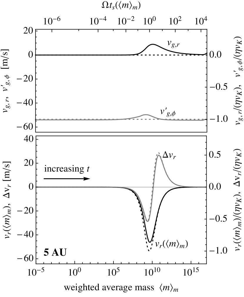
To test the effect of fractional backreaction, we have also simulated porous aggregation using Equations (48) and (49) instead of Equations (6) and (18) for the aggregate velocities. However, it is found that the effect of backreaction is so small that the resulting dust evolution is hardly distinguishable from that presented in Section 3. The upper panel of Figure 13 shows the temporal evolution of the gas velocities and observed in this simulation as a function of the weighted average mass . We see that the observed gas velocities deviate at most only by from the velocities when the backreaction is absent (dotted lines). As a result of this, the inward velocity of aggregates with is decreased only by even when (see the black solid curve in the lower panel of Figure 13). The above result can be understood in the following way. As found from the definitions of and (Equations (52) and (53)), the effect of the backreaction is significant only when the density of dust coupled to the gas () is comparable to or higher than the gas density. When , the density of the coupled dust at the midplane is , where is the midplane gas density and we have used that (Equation (3)) and (the latter is true as long as ). When , the dust density does exceed the gas density at the midplane, but the most part of the dust mass is now carried by decoupled () aggregates, which do not affect the gas motion.333Indeed, and are insensitive to particles because the factors and decrease faster than the spatial dust density increases (see Equation (3)) . Thus, the density of coupled dust is always lower than the gas density, and hence the backreaction effect is insignificant at all times.
Furthermore, the effect on the differential drift velocity is even less significant, because the decreases in the inward velocities nearly cancel out. As an example, the gray solid and dotted curves in the lower panel of Figure 13 show the differential radial velocity between aggregates of stopping times and obtained from the simulations with and without the backreaction, respectively. We see that the maximum values of , which are reached when , differ only by . Therefore, the frictional backreaction from dust to gas hardly affects the drift-induced collision velocity between dust aggregates.
5.2.2 Streaming Instability
The backreaction of dust on gas causes another phenomenon, the so-called streaming instability (Youdin & Goodman, 2005). This means that the equilibrium gas–dust motion as described by Equations (6)–(18) is unstable against perturbation. One important consequence of this instability is rapid clumping of marginally decoupled () dust particles (e.g., Johansen & Youdin, 2007; Johansen et al., 2007; Bai & Stone, 2010a). The clumping proceeds in a runaway manner (i.e., turbulent diffusion no longer limits the clumping) once the dust density exceeds the gas density at the midplane (e.g., Johansen & Youdin 2007; see also the analytic explanation of this by Johansen et al. 2009). The runaway clumps could be eventually gravitationally bound and form 100 km sized planetesimals (Johansen et al., 2007). For more tightly coupled () particles, however, the clumping occurs only moderately unless the dust-to-gas surface density ratio is high and/or the radial drift speed is low (Johansen et al., 2009; Bai & Stone, 2010b). This is also true for loosely coupled particles () for which the interaction with the gas is weak.
As seen in Section 3.2, porous aggregates are able to reach in inner regions of disks. These aggregates likely trigger the streaming instability and can even experience runaway collapse. However, it is not obvious whether the clumps really experience the runaway collapse, since the growth timescale of the aggregates can be as short as one orbital period (see Section 5.1), which is comparable to the growth time of the streaming instability at (Youdin & Goodman, 2005). If the aggregates cross faster than the clumps develop, planetesimal formation will occur via direct collisional growth rather than gravitational instability. In order to address this issue, we will need to simulate coagulation and streaming instability simultaneously.
5.3. Fragmentation Barrier
In this study, we have assumed that all aggregate collisions lead to sticking. This assumption breaks down if the collisional velocity is so high that the collision involves fragmentation and erosion. If the mass loss due to fragmentation and erosion is significant, it acts as an obstacle to planetesimal formation (the so-called fragmentation barrier; e.g., Brauer et al. 2008a). Here, we discuss the validity and possible limitations of this assumption.
Recent -body simulations predict that very fluffy aggregates made of sized icy particles experience catastrophic disruption at collision velocities (Wada et al., 2009). If a large aggregate grows mainly through collisions with similar-sized ones (which is true in our simulations; see Figure 9), the collision velocity at is dominated by the turbulence-driven velocity (Section 2.3.2). If the disk is optically thin and moderately turbulent () as in our model, the collision velocity is at , so catastrophic disruption is likely insignificant for such collisions. However, if turbulence is as strong as , the collision velocity at and goes up to . In protoplanetary disks, strong turbulence with can be driven by magnetorotational instability (MRI; e.g., Balbus & Hawley 1998). If such strong turbulence exists, fragmentation becomes no more negligible even for icy aggregates. Besides, the collision velocity can become higher than the above estimate when a large aggregate collides with much smaller ones, since the collision velocity is then dominated by the radial drift motion. For example, the differential radial drift velocity between an aggregate and a much smaller one is as high as in optically thin disks. At such a high velocity, erosion by small aggregates can also slow down the growth of aggregates, although net growth might be possible (see, e.g., Teiser & Wurm, 2009; Teiser et al., 2011).
On the other hand, resupply of small dust particles by fragmentation/erosion has positive effects on dust growth. First, small dust particles stabilize MRI-driven turbulence because they efficiently capture ionized gas particles and thereby reduce the electric conductivity of the gas (e.g., Sano et al., 2000). This process generally leads to the reduction of the gas random velocity (and hence the reduction of turbulence-induced collision velocity), especially when the magnetic fields threading the disk are weak (Okuzumi & Hirose, 2011). In addition, small fragments enhance the optical thickness of the disk, and thus reduce the temperature of the gas in the interior of the disk (given that turbulence is stabilized there). Since the radial drift velocity is proportional to the gas temperature, this leads to the reduction of the drift-induced collision velocity. In the limit of large optical depths, the gas temperature is reduced by a factor near the midplane (Kusaka et al., 1970), resulting in the reduction of the drift-induced collision velocity to . These effects may help the growth of large aggregates beyond the fragmentation barrier.
The size of monomers is another key factor. Although we have assumed monodisperse monomers of , the size of interstellar dust particles ranges from nanometers to microns. It is suggested both theoretically (Chokshi et al., 1993; Dominik & Tielens, 1997) and experimentally (Blum & Wurm, 2008) that the threshold velocity for sticking is roughly inversely proportional to . Thus, inclusion of larger monomers generally leads to the decrease in the sticking efficiency. However, it is not obvious whether aggregates composed of multi-sized interstellar particles are mechanically weaker or stronger than aggregates considered in this study. For example, if the monomer size distribution obeys that of interstellar dust particles, (Mathis et al., 1977), the total mass of the aggregates is dominated by the largest ones ( and hence ). Nevertheless, the existence of smaller monomers can still be important, since the binding energy per contact is proportional to (Chokshi et al., 1993; Dominik & Tielens, 1997) and hence the total binding energy tends to be dominated by the smallest ones (). The net effect of multi-sized monomers needs to be clarified by future numerical as well as laboratory experiments.
Another issue about the growth efficiency of icy aggregates arises from sintering. Sintering is redistribution of ice molecules on solid surfaces due to vapor transport and other effects. In this process, ice molecules tend to fill dipped surfaces (i.e., surfaces with negative surface curvature) since the equilibrium vapor pressure decreases with decreasing the surface curvature. In an aggregate composed of equal-sized icy monomers, this process leads to growth of the monomer contact areas (Sirono, 2011b) and consequently to enhancement of the aggregate’s mechanical strength such as . Significant growth of the contact areas could cause the reduction of the aggregate’s sticking efficiency since the dissipation of the collision energy through internal rolling/sliding motion could then be suppressed (Sirono, 1999). Furthermore, if the monomers have different sizes, sintering leads to evaporation of smaller monomers (having higher positive curvature), which may result in the breakup of the aggregate (Sirono, 2011a). Therefore, sintering can prevent the growth of icy aggregates near the snow line where sintering proceeds rapidly. Sirono (2011b) shows that the timescale of sintering falls below yr in the region between the snow line () and for the radial temperature adopted in our study. This is comparable to the timescale on which submicron-sized icy particles grow into macroscopic objects in this region (see Figure 7). However, if the disk is passive and optically thick (Kusaka et al., 1970), no icy materials (including and ) undergo rapid sintering at (Sirono, 2011b). Moreover, the required high optical depth can be provided by tiny fragments that would result from the sintering-induced fragmentation itself. Consistent treatment of the two competing effects is necessary to precisely know the location where sintering is really problematic.
To summarize, whether icy aggregates survive catastrophic fragmentation and erosion crucially depends on the environment of protoplanetary disks as well as on the size distribution of the aggregates and constituent monomers. However, we emphasize that icy aggregates can survive within a realistic range of disk conditions as explained above. Indeed, the range is much wider than that for rocky aggregates, for which catastrophic disruption occurs at collision velocities as low as a few (Blum & Wurm, 2008; Wada et al., 2009; Güttler et al., 2010). In order to precisely predict in what conditions icy aggregates overcome the fragmentation barrier, we need to take into account the mass loss due to fragmentation/erosion and the reduction of collision velocities due to the resupply of small particles in a self-consistent way. This will be done in our future work.
5.4. Validity and Limitations of the Porosity Model
Aggregates observed in our simulation have very low internal densities. This is a direct consequence of the porosity model we adopted (Equation (15)). Here, we discuss the validity and limitations of our porosity model.
As mentioned in Section 2.3.1, our porosity change recipe at is based on head-on collision experiments of similar-sized aggregates. In our simulation, dust growth is indeed dominated by collision with similar-sized aggregates (see Section 3.2.1), so our result is unlikely affected by the limitation of the porosity model regarding the size ratio. By contrast, the neglect of offset collision may cause underestimation of the porosity increase, since the impact energy is spent for stretching rather than compaction at offset collision (Wada et al., 2007; Paszun & Dominik, 2009). If this is the case, then the breakthrough of the radial drift barrier can occur even outside .
On the other hand, the formation of low-density dust aggregates is apparently inconsistent with the existence of massive and much less porous aggregates in our solar system. For example, comets, presumably the most primitive dust “aggregates” in the solar system, are expected to have mean internal densities of (e.g., Greenberg & Hage, 1990). Since our porosity model does not explain the formation of such large and less porous “aggregates,” there should exist any missing compaction mechanisms.
One possibility is static compression due to gas drag and self-gravity. Although static compression is ignored in our porosity model, it can contribute to compaction of aggregates that are massive or decoupled from the gas motion. For relatively compact () dust cakes made of micron-sized particles, static compaction is observed to occur at static pressure (Blum & Schräpler, 2004; Güttler et al., 2009). By contrast, the static compression strength has not yet been measured so far for icy aggregates with very low internal densities (). However, for future reference, it will be useful to estimate here the static pressures due to gas drag and self-gravity.
The ram pressure, the gas drag force per unit area, is given by , where is the drag coefficient and is the gas–dust relative speed (see Section 5.1). At , the gas–dust relative speed is approximately equal to . Thus, assuming Newton’s drag law for aggregates (Section 5.1), the ram pressure at is estimated as
| (54) |
independently of aggregate properties. Thus, if the static compression strength of our high porous aggregates is lower than , compression of the aggregates will occur at due to ram pressure.
The static pressure due to self-gravity is estimated from dimensional analysis as
| (55) |
For and , which correspond to the aggregates observed in our simulation (Figure 5), the gravitational pressure is much weaker than the ram pressure. However, since , compression due to self-gravity becomes important for much heavier aggregates. For example, if as is for the aggregates observed in our simulation, exceeds at , which is comparable to the mass of comet Halley. Moreover, since , gravitational compaction will proceed in a runaway manner unless the static compression strength increases more rapidly than . Thus, static compression due to self-gravity may be a key to fill the gap between our high porous aggregates and more compact planetesimal-mass bodies in the solar system.
6. Summary and Outlook
We have investigated how the porosity evolution of dust aggregates affects their collisional growth and radial inward drift. We have applied a porosity model based on -body simulations of aggregate collisions (Suyama et al., 2008, 2012). This porosity model allows us to study the porosity change upon collision for a wide range of impact energies. As a first step, we have neglected the mass loss due to collisional fragmentation and instead focused on dust evolution outside the snow line, where aggregates are mainly composed of ice and hence catastrophic fragmentation may be insignificant (Wada et al., 2009). Our findings are summarized as follows.
-
1.
Icy aggregates can become highly porous even if collisional compression is taken into account (Section 3.2). Our model calculation suggests that the internal density of icy aggregates at falls off to by the end of the initial fractal growth stage and then is kept to this level until the aggregates decouple from the gas motion (Figure 10). Stretching of merged aggregates at offset collisions, which is not taken into account in our porosity model, could further decrease the internal density (Wada et al., 2007; Paszun & Dominik, 2009).
-
2.
A high porosity triggers significant acceleration in collisional growth. This acceleration is a natural consequence of particles’ aerodynamical property in the Stokes regime, i.e., at particle radii larger than the mean free path of the gas molecules (Section 4). The porosity (or internal density) of an aggregate determines whether the aggregate reaches the Stokes regime before the radial drift stalls its growth. Compact aggregates tend to drift inward before experiencing the rapid growth, while highly porous aggregates are able to experience it over a wide range of the orbital radius (Figure 11).
-
3.
The growth acceleration enables the aggregates to overcome the radial drift barrier in inner regions of the disks. Our model calculation shows that the breakthrough of the radial drift barrier can occur at orbital radii less than in the MMSN (Figure 5). A higher disk mass allows this to occur at larger orbital radii or higher internal densities (Figure 12). The radial drift barrier has been commonly thought to be one of the most serious obstacles against planetesimal formation. Our result suggests that, if the fragmentation of icy aggregates is truly insignificant (see Section 5.3), formation of icy planetesimals is possible via direct collisional growth of submicron-sized icy particles even without an enhancement of the initial dust-to-gas mass ratio.
-
4.
Further out in the disk, the growth of porous icy aggregates is still limited by the radial drift barrier, but their inward drift results in enhancement of the dust surface density in the inner region (Figure 6). This enhancement may help the core of giant planets to form within a disk lifetime (Kobayashi et al., 2010, 2011).
We remark that the quick growth in the Stokes regime was also observed in recent coagulation simulations by Birnstiel et al. (2010, see their Figure 11) and Zsom et al. (2011, see their Figure 3). Birnstiel et al. (2010) observed the breakthrough of the radial drift barrier only at small orbital radii () since they assumed compact aggregation. Zsom et al. (2011) found rapid growth of porous aggregates in the Stokes regime, but did not consider the loss of the dust surface density through radial drift. What we have clarified in this study is that porosity evolution indeed enables the breakthrough of the radial drift barrier at much lager orbital radii.
The porosity evolution can even influence the evolution of solid bodies after planetesimal formation. It is commonly believed that the formation of protoplanets begins with the runaway growth of a small number of planetesimals due to gravitational focusing (e.g., Wetherill & Stewart, 1989). The runaway growth requires a sufficiently high gravitational escape velocity relative to the collision velocity. Since the escape velocity decreases with decreasing internal density (), it is possible that a high porosity delays the onset of the runaway and thereby affects its outcome. For example, a recent protoplanet growth model including collisional fragmentation/erosion (Kobayashi et al., 2010, 2011) suggests that planetesimals need to have grown to before the runaway growth begins in order to enable the formation of gas giant planets within the framework of the core accretion scenario (Mizuno, 1980; Pollack et al., 1996). The size of the “initial” planetesimals can even determine the mass distribution of asteroids in the main belt (Morbidelli et al., 2009; Weidenschilling, 2011). As we pointed out in Section 5.4, compaction of large and massive aggregates may occur through static compression due to gas drag or self gravity. To precisely determine when it occurs is beyond the scope of this work, but it will be thus important to understand later stages of planetary system formation. We will address this in future work.
References
- Adachi et al. (1976) Adachi, I., Hayashi, C., & Nakazawa, K. 1976, Prog. Theor. Phys., 56, 1756
- Bai & Stone (2010a) Bai, X.-N., & Stone, J. 2010a, ApJ, 722, 1437
- Bai & Stone (2010b) Bai, X.-N., & Stone, J. 2010b, ApJ, 722, L220
- Balbus & Hawley (1998) Balbus, S. A., & Hawley, J. F. 1998, Rev. Mod. Phys., 70, 1
- Barge & Sommeria (1995) Barge, P., & Sommeria, J. 1995, A&A, 295, L1
- Birnstiel et al. (2009) Birnstiel, T., Dullemond, C. P., & Brauer, F. 2009, A&A, 503, L5
- Birnstiel et al. (2010) Birnstiel, T., Dullemond, C. P., & Brauer, F. 2010, A&A, 513, 79
- Birnstiel et al. (2012) Birnstiel, T., Klahr, H., & Ercolano, B. 2012, A&A, 539, A148
- Blum (2004) Blum, J. 2004, in ASP Conf. Ser. 309, Astrophysics of Dust, ed. A. N. Witt, G.C. Clayton, & B. T. Draine (San Francisco, CA: ASP), 369
- Blum & Schräpler (2004) Blum, J., & Schräpler, R. 2004, Phys. Rev. Lett., 93, 115503
- Blum & Wurm (2000) Blum, J., & Wurm, G. 2000, Icarus, 143, 138
- Blum & Wurm (2008) Blum, J., & Wurm, G. 2008, ARA&A, 46, 21
- Brauer et al. (2008a) Brauer, F., Dullemond, C. P., & Henning, Th. 2008a, A&A, 480, 859
- Brauer et al. (2008b) Brauer, F., Henning, Th., & Dullemond, C. P. 2008b, A&A, 487, L1
- Chokshi et al. (1993) Chokshi, A., Tielens, A. G. G. M., & Hollenbach, D. 1993, ApJ, 407, 806
- Dominik & Tielens (1995) Dominik, C., & Tielens, A. G. G. M. 1995, Phil. Mag. A, 72, 783
- Dominik & Tielens (1997) Dominik, C., & Tielens, A. G. G. M. 1997, ApJ, 480, 647
- Dubrulle et al. (1995) Dubrulle, B., Morfill, G., & Sterzik, M. 1995, Icarus, 114, 237
- Dubrulle & Valdettaro (1992) Dubrulle, B., & Valdettaro, L. 1992, A&A, 263, 387
- Fromang & Papaloizou (2006) Fromang, S., & Papaloizou, J. 2006, A&A, 452, 751
- Goldreich & Ward (1973) Goldreich, P., & Ward, W. R. 1973, ApJ, 183, 1051
- Greenberg & Hage (1990) Greenberg, J. M., & Hage, J. I. 1990, ApJ, 361, 260
- Gundlach et al. (2011) Gundlach, B., Kilias, S., Beitz, E., & Blum, J. 2011, Icarus, 214, 717
- Güttler et al. (2010) Güttler, C., Blum, J., Zsom, A., Ormel, C. W., & Dullemond, C. P. 2010, A&A, 513, A56
- Güttler et al. (2009) Güttler, C., Krause, M., Geretshauser, R. J., Speith, R., & Blum, J. 2009, ApJ, 701, 130
- Hayashi (1981) Hayashi, C. 1981, Prog. Theor. Phys. Suppl., 70, 35
- Hayashi et al. (1985) Hayashi, C., Nakazawa, K., & Nakagawa, Y. 1985, in Protostars and Planets II, ed. D. C. Black & M. S. Matthews (Tucson, AZ: Univ. Arizona Press), 1100
- Hirose & Turner (2011) Hirose, S., & Turner, N. J. 2011, ApJ, 732, L30
- Johansen et al. (2006) Johansen, A., Klahr, H., & Mee, A. J. 2006, MNRAS, 370, L71
- Johansen et al. (2007) Johansen, A., Oishi, J. S., Mac Low, M.-M., et al. 2007, Nature, 448, 1022
- Johansen & Youdin (2007) Johansen, A., & Youdin, A. 2007, ApJ, 662, 627
- Johansen et al. (2009) Johansen, A., Youdin, A., & Mac Low, M.-M. 2009, ApJ, 704, L75
- Klahr & Henning (1997) Klahr, H. H., & Henning, T. 1997, Icarus, 128, 213
- Kobayashi et al. (2011) Kobayashi, H., Tanaka, H., & Krivov, A. V. 2011, ApJ, 738, 35
- Kobayashi et al. (2010) Kobayashi, H., Tanaka, H., Krivov, A. V., & Inaba, S. 2010, Icarus, 209, 836
- Kretke & Lin (2007) Kretke, K. A., & Lin, D. N. C. 2007, ApJ, 664, L55
- Kusaka et al. (1970) Kusaka, T., Nakano, T., & Hayashi, C. 1970, Prog. Theor. Phys., 44, 1580
- Langkowski et al. (2008) Langkowski, D., Teiser, J., & Blum, J. 2008, ApJ, 675, 764
- Mathis et al. (1977) Mathis, J. S., Rumpl, W., & Nordsieck, K. H. 1977, ApJ, 217, 425
- Matthews et al. (2012) Matthews, L. S., Land, V., & Hyde, T. W. 2012, ApJ, 744, 8
- Mizuno (1980) Mizuno, H. 1980, Prog. Theor. Phys., 64, 544
- Morbidelli et al. (2009) Morbidelli, A., Bottke, W. F., Nesvorný, D., & Levison, H. F. 2009, Icarus, 204, 558
- Mukai et al. (1992) Mukai, T., Ishimoto, H., Kozasa, T., Blum, J., & Greenberg, J. M. 1992, A&A, 262, 315
- Nakagawa et al. (1981) Nakagawa, Y., Nakazawa, K., & Hayashi, C. 1981, Icarus, 45, 517
- Nakagawa et al. (1986) Nakagawa, Y., Sekiya, M., & Hayashi, C., 1986, Icarus, 67, 375
- Okuzumi (2009) Okuzumi, S. 2009, ApJ, 698, 1122
- Okuzumi & Hirose (2011) Okuzumi, S., & Hirose, S. 2011, ApJ, 742, 65
- Okuzumi et al. (2009) Okuzumi, S., Tanaka, H., & Sakagami, M-a. 2009, ApJ, 707, 1247
- Okuzumi et al. (2011a) Okuzumi, S., Tanaka, H., Takeuchi, T., & Sakagami, M-a., 2011a, ApJ, 731, 95
- Okuzumi et al. (2011b) Okuzumi, S., Tanaka, H., Takeuchi, T., & Sakagami, M-a., 2011b, ApJ, 731, 96
- Ormel & Cuzzi (2007) Ormel, C. W., & Cuzzi, J. N. 2007, A&A, 466, 413
- Ormel et al. (2007) Ormel, C. W., Spaans, M., & Tielens, A. G. G. M. 2007, A&A, 461, 215
- Paszun & Dominik (2009) Paszun, D., & Dominik, C. 2009, A&A, 507, 1023
- Pinilla et al. (2012) Pinilla, P., Birnstiel, T., Ricci, L., et al. 2012, A&A, 538, A114
- Pollack et al. (1996) Pollack, J. B., Hubickyj, O., Bodenheimer, P., et al. 1996, Icarus, 124, 62
- Safronov (1969) Safronov, V. S. 1969, Evolution of the Protoplanetary Cloud and Formation of the Earth and the Planets (Moscow: Nauka)
- Sano et al. (2000) Sano, T., Miyama, S. M., Umebayashi, T., & Nakano, T. 2000, ApJ, 543, 486
- Sekiya (1998) Sekiya, M. 1998, Icarus, 133, 298
- Shakura & Sunyaev (1973) Shakura, N. I., & Sunyaev, R. A. 1973, A&A, 24, 337
- Sirono (1999) Sirono, S. 1999, A&A, 347, 720
- Sirono (2011a) Sirono, S. 2011a, ApJ, 733, L41
- Sirono (2011b) Sirono, S. 2011b, ApJ, 735, 131
- Suyama et al. (2008) Suyama, T., Wada, K., & Tanaka, H. 2008, ApJ, 684, 1310
- Suyama et al. (2012) Suyama, T., Wada, K., Tanaka, H., & Okuzumi, S. 2012, ApJ, in press (arXiv:1205.1894)
- Suzuki et al. (2010) Suzuki, T. K., Muto, T., & Inutsuka, S. 2010, ApJ, 718, 1289
- Tanaka et al. (2005) Tanaka, H., Himeno, Y., & Ida, S. 2005, ApJ, 625, 414
- Teiser et al. (2011) Teiser, J., Küpper, M., & Wurm, G. 2009, Icarus, 215, 596
- Teiser & Wurm (2009) Teiser, J., & Wurm, G. 2009, MNRAS, 393, 1584
- Toomre (1964) Toomre, A. 1964, ApJ, 139, 1217
- Turner et al. (2010) Turner, N. J., Carballido, A., & Sano, T. 2010, ApJ, 708, 188
- Wada et al. (2007) Wada, K., Tanaka, H., Suyama, T., Kimura, H., & Yamamoto, T. 2007, ApJ, 661, 320
- Wada et al. (2008) Wada, K., Tanaka, H., Suyama, T., Kimura, H., & Yamamoto, T. 2008, ApJ, 677, 1296
- Wada et al. (2009) Wada, K., Tanaka, H., Suyama, T., Kimura, H., & Yamamoto, T. 2009, ApJ, 702, 1490
- Wada et al. (2011) Wada, K., Tanaka, H., Suyama, T., Kimura, H., & Yamamoto, T. 2011, ApJ, 737, 36
- Weidenschilling (1977) Weidenschilling, S. J. 1977, MNRAS, 180, 57
- Weidenschilling (2011) Weidenschilling, S. J. 2011, Icarus, 214, 671
- Weidenschilling & Cuzzi (1993) Weidenschilling, S. J., & Cuzzi, J. N. 1993, in Protostars and Planets III, ed. E. H. Levy & J. I. Lunine (Tucson, AZ: Univ. Arizona Press), 1031
- Weidling et al. (2009) Weidling, R., Güttler, C., Blum, J., & Brauer, F. 2009, ApJ, 696, 2036
- Wetherill & Stewart (1989) Wetherill, G. W., & Stewart, G. R. 1989, Icarus, 77, 330
- Whipple (1972) Whipple, F. L. 1972, in From Plasma to Planet, ed. A. Elvius (New York: Wiley Interscience), 211
- Windmark et al. (2012) Windmark, F., Birnstiel, T., Güttler, C., et al. 2012, A&A, 540, A73
- Youdin & Goodman (2005) Youdin, A. N., & Goodman, J. 2005, ApJ, 620, 459
- Youdin & Lithwick (2007) Youdin, A. N., & Lithwick, Y. 2007, Icarus, 192, 588
- Zsom et al. (2011) Zsom, A., Ormel, C. W., Dullemond, C. P., & Henning, T. 2011, A&A, 534, A73
- Zsom et al. (2010) Zsom, A., Ormel, C. W., Güttler, C., Blum, J., & Dullemond, C. P. 2010, A&A, 513, A57