Memristive circuits simulate memcapacitors and meminductors
Abstract
We suggest electronic circuits with memristors (resistors with memory) that operate as memcapacitors (capacitors with memory) and meminductors (inductors with memory). Using a memristor emulator, the suggested circuits have been built and their operation has been demonstrated, showing a useful and interesting connection between the three memory elements.
Index Terms:
Memory, Analog circuits, Analog memories.Introduction: Memcapacitive and meminductive systems are two recently postulated classes of circuit elements with memory [1] that complement the class of memristive systems [2, 3]. Their main characteristic is a hysteretic loop - which may or may not pass through the origin [1] - in their constitutive variables (charge-voltage for memcapacitors and current-flux for meminductors) when driven by a periodic input, and, unlike memristors, they can store energy. As of today, a few systems have been found to operate as memcapacitors and meminductors (see [1] and references therein). However, these are neither available on the market yet, nor their properties can be easily tuned to investigate their role in more complex circuits. The same can be said about memristive systems. Therefore, electronic emulators of such memory elements that could be easily built and tuned would be highly desirable. We have previously designed and built a memristor emulator and shown its use in neuromorphic and programmable analog circuits [4, 5]. In this Letter, we use such memristor emulator to design and build memcapacitor and meminductor emulators, and prove experimentally their main properties. Since all of these emulators can be built from inexpensive off-the-shelf components we expect them to be extremely useful in the design, understanding and simulations of complex circuits with memory.
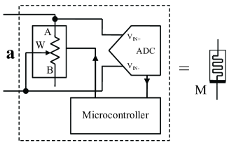
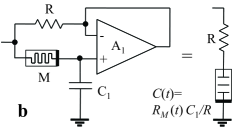
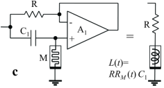
Proposed circuits: The proposed circuits of memcapacitor and meminductor emulators are shown in Fig. 1(b) and (c), respectively, together with the memristor emulator in Fig. 1(a). The memristor emulator is implemented as in Refs [4, 5] and consists of a digital potentiometer whose resistance is continuously updated by a microcontroller and determined by pre-programmed equations of current-controlled or voltage-controlled memristive systems. In our experiments, the memristance is governed by an activation-type model [5, 6] defined by with
| (1) | |||||
where is the voltage across the memristor, and is the step function. We choose for this work the following parameters , k(Vs) (used in the memcapacitor emulator), M(Vs) (used in the meminductor emulator), V, k and k.
The memcapacitor emulator consists of this memristor , a capacitor and a resistor connected to an operational amplifier as shown in Fig. 1b. Since the operational amplifier keeps nearly equal voltages at its positive and negative inputs, the voltage on the capacitor is applied to the right terminal of . Therefore, we can think that an effective capacitor with a time-dependent capacitance is connected to the right terminal of , so that the relation holds. (Note that the voltage at the capacitor is equivalent to the voltage, , at the negative terminal of the operational amplifier.) This allows us to determine the capacitance as since . In the limit , we obtain the approximate equivalent circuit shown on the right of Fig. 1b. On the other hand, the meminductor emulator is similar to the design of a gyrator with a memristor replacing a resistor, and the equivalent inductance , as it is evident from Fig. 1c. In both cases, the time dependence of the equivalent capacitance, , and inductance, , is due to the time dependence of .
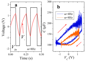

In order to prove that these circuits emulate the behavior of memcapacitors and meminductors, we have analyzed their response under the application of a square wave signal. This is shown in Fig. 2, where, on the left panel, we show both the input voltage and the voltage at the negative terminal of the operational amplifier , and, on the right panel, the equivalent capacitance of the memcapacitor emulator at two values of frequency of the square wave signal. Clear hysteresis loops are visible in the capacitance as a function of the voltage at the capacitor . We also note that the capacitance hysteresis is frequency dependent: the loop is much smaller at the higher frequency of 8Hz. This is a manifestation of a typical property of memory circuit elements [1] that at high frequencies behave as linear elements. The fluctuations of in Fig. 2b are related to the limited resolution of our data acquisition system and some noise in the circuit.
Similar considerations apply to the meminductor emulator as demonstrated in Fig. 3. Here, it is clearly seen that the shape of the signal (which in this case is equal to the voltage on the equivalent inductor ) depends on the polarity of applied voltage. We extracted numerically the equivalent inductance from and signals and found that it contains a considerable amount of noise. Less noisy estimation of equivalent inductance is obtained using a fit of signal by exponentially decaying curves as demonstrated in Fig. 3a giving a decaying time , from which we have extracted . Since the memristor emulator state in the meminductor emulator changes fast (its parameters are given below Eq. (1)), the equivalent inductance switches between two limiting values as shown schematically in Fig. 3b.
Finally, we would like to mention that although the suggested emulators reproduce the essential features of real memcapacitors and meminductors, certain aspects are different. In particular, the designed emulators are active devices requiring a power source for their operation. More importantly, these emulators do not actually store energy, which might be a limitation in specific applications. However, from the point of view of circuit response, almost any kind of memcapacitor and meminductor operation model can be realized using an appropriate memristor-emulator operation algorithm.
Conclusions: We have demonstrated that simple circuits with memristors can exhibit both memcapacitive and meminductive behavior. Memcapacitor and meminductor emulators have been designed and built using the previously suggested memristor emulator [4, 5] since solid-state memristors are not available yet. These emulators can be created from inexpensive off-the-shelf components, and as such they provide powerful tools to understand the different functionalities of these newly suggested memory elements without the need of expensive material fabrication facilities. We thus expect they will be of use in diverse areas ranging from non-volatile memory applications to neuromorphic circuits.
Acknowledgment: This work has been partially funded by the NSF grant No. DMR-0802830.
References
- [1] M. Di Ventra, Y. V. Pershin, and L. O. Chua, “Circuit elements with memory: memristors, memcapacitors and meminductors,” Proc. IEEE, vol. 97, pp. 1717–1724, 2009.
- [2] L. O. Chua and S. M. Kang, “Memristive devices and systems,” Proc. IEEE, vol. 64, no. 2, pp. 209–223, 1976.
- [3] L. O. Chua, “Memristor - the missing circuit element,” IEEE Trans. Circuit Theory, vol. 18, no. 5, pp. 507–519, 1971.
- [4] Y. V. Pershin and M. Di Ventra, “Experimental demonstration of associative memory with memristive neural networks,” arXiv:0905.2935, 2009.
- [5] ——, “Practical approach to programmable analog circuits with memristors,” arXiv:0908.3162, 2009.
- [6] Y. V. Pershin, S. La Fontaine, and M. Di Ventra, “Memristive model of amoeba’s learning,” Phys. Rev. E, vol. 80, p. 021926, 2009.