Deflection of suspended graphene by a transverse electric field
Abstract
We investigate the electromechanical response of doubly clamped graphene nanoribbons to a transverse gate voltage. An analytical model is developed to predict the field-induced deformation of graphene nanoribbons as a function of field intensity and graphene geometry. This model is validated thought atomistic simulations using the combination of a constitutive charge-dipole model and a pseudo-chemical many-body potential. As a newly observed effect of electric polarization, this field-induced deflection allows the graphene to oscillate at its natural frequency, which is found to decrease dramatically with increasing graphene size.
If we bring a glass rod electrically charged by rubbing with silk near a hair, the hair will be attracted to the rod. Here we demonstrate a similar electrostatic effect occurring in a graphene nanoribbon, a one-atom-thick carbon crystalline layer, which has been shown to have interesting electronic properties Castro Neto et al. (2009); Beenakker (2008) at nanoscale. In particular, graphene’s electronic gap tunable in external electromagnetic fields makes it desirable for numerous applications in nanoelectronic devices Novoselov et al. (2004); Son et al. (2006a); Yang et al. (2007); Han et al. (2007); Castro et al. (2007); Novikov (2007); Yan et al. (2007). In such devices, the graphene is usually suspended between supports and exposed to an external electric field Bunch et al. (2007). Since electronic transport properties of graphene are highly sensitive to the change of atomic structure Son et al. (2006b); Han et al. (2007), understanding its mechanical behaviors in response to an applied electric field is a crucial part for the development of graphene-based electronic and electromechanical devices.
In recent experiments, vibrations induced by an electric field were observed in carbon nanotubes (CNTs) Poncharal et al. (1999). This property has then been exploited in the design of a number of CNT-based nanoelectromechanical devices Anantram and Leonard (2006). It would not be surprising if graphene exhibits similar structural instability in an electric field as nanotubes do Wang and Philippe (2009), in view of the large similarity in their in-plane electric polarizabilities Kozinsky and Marzari (2006) and mechanical properties Lee et al. (2008). Indeed, as an extremely thin membrane with well-defined electronic properties and low lateral stiffness, a suspended graphene sheet should be an ideal material for use in an electromechanical oscillator or resonator.
When an electric field is applied across a thin neutral molecule, a moment of force acting on the molecule will arise as a result of electric polarization. It bends the molecule to the field direction Joselevich and Lieber (2002). By such a deflection, electrical potential energy is converted and stock in the molecular structure. The mechanism of this energy conversion relies on the interaction between the electric field and the polarized charges on the molecule. This energy can be released in a form of mechanical oscillation by removing the field as far as the deflection of the molecule is elastic Garcia-Sanchez et al. (2008).
A natural question to ask at this point is, how does the shape of graphene change in response to applied transverse electric fields? In this work, we present an analytical approach to predict deformations of graphene nanoribbons (GNRs) by an electric field, demonstrating the coupling between the electric polarization and the mechanical resistance of graphene. This approach is validated through molecular simulations in view of the difficulty to establish an experimental quantification system of nanoscale electric polarization effects. Resonance frequency of GNRs with different length is measured by simulating vibration of GNRs by means of molecular dynamics (MD).
We performed molecular simulations Wang and Philippe (2009) to compute the deflection of suspended GNRs by an electric field, minimizing the total potential energy of the system, which consists of two terms: an internal potential due to the C-C chemical bonds , and an external potential arising from the interaction with an external electric field. is calculated using the adaptive interatomic reactive empirical bond order (AIREBO) potential function Stuart et al. (2000), which has been used in recent studies on mechanical properties of CNTs Ni et al. (2002) and GNRs Shenoy et al. (2008). is computed using a constitutive Gaussian-regularized electrostatic model, in which each atom is modeled as an induced dipole and a quantity of free charge Mayer (2007),
| (1) |
where is the total number of atoms, is the electron affinity, and stand for the external potential and electric field, respectively. and are the electrostatic interacting tensors. This model has recently been validated through electrostatic force microscopy experiments on CNTs Wang et al. (2008). Further details about the simulation can be found in Refs.Wang and Devel (2007); Wang and Philippe (2009).
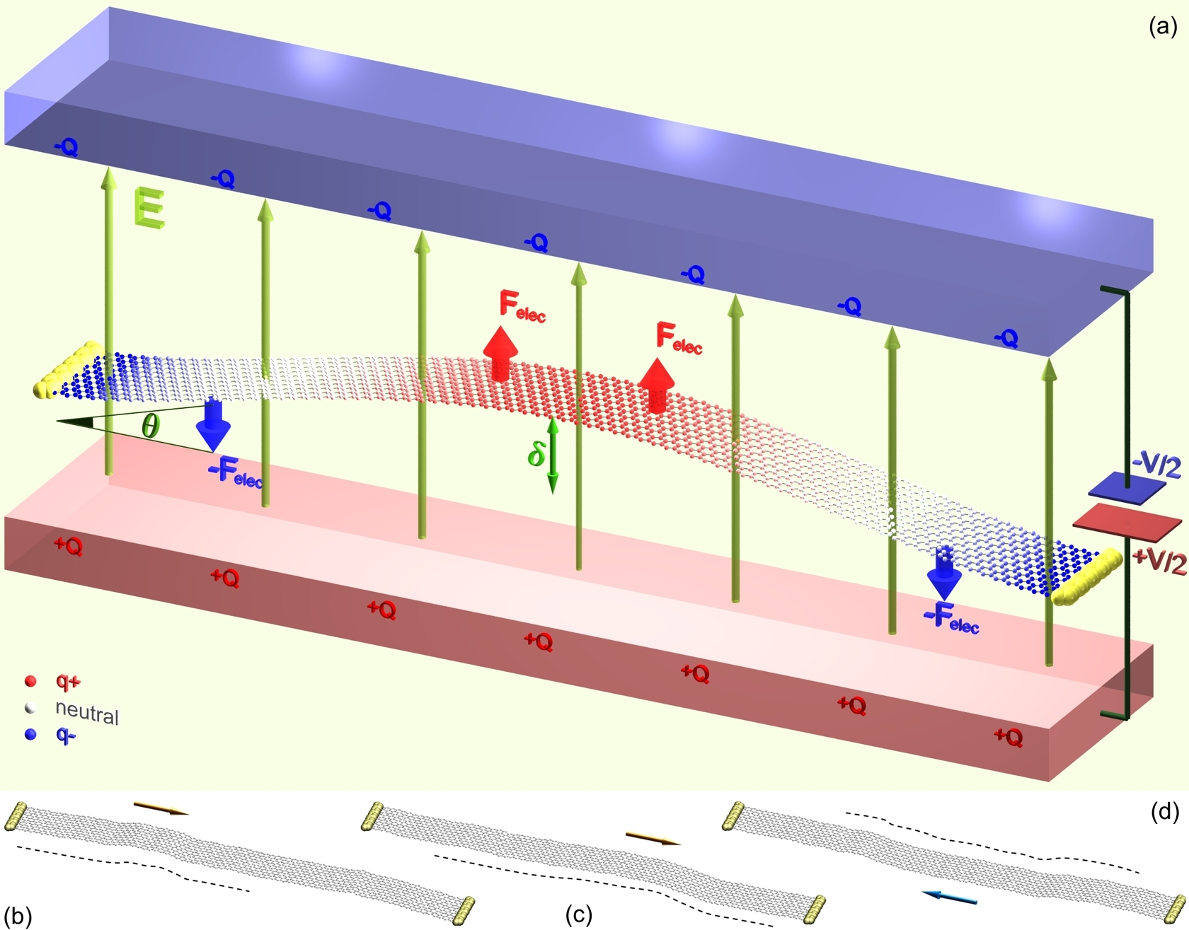
Technically, no deformation will take place if an electric field is applied perfectly perpendicular to the graphene surface, because the induced dipole is already parallel to the field direction hence the induced moment of electrostatic force is zero Guo and Guo (2003). However, this ideal situation could be seldom attained due to previously predicted intrinsic height fluctuations Fasolino et al. (2007) and edge stresses Shenoy et al. (2008) in graphene. During verification of these predictions using MD simulations based on the AIREBO potential, we have observed interesting elastic wave propagation on the surface of graphene at room temperature (see Fig. 1 (b-d)). The typical speed and maximal vertical amplitude of this wave propagation in the graphene are found to be about km/s and nm, respectively. The elastic waves (so called intrinsic ripples) make the shape of GNRs more or less naturally curved. This natural curvature provides possibility for an electric field to shift negative and positive charges to opposite directions in graphene.
To show the physical principle of electric deflection, we depict in Fig. 1 (a) the profile of polarized charges in suspended graphene by a transverse electric field (computational details can be found elsewhere Wang (2009)). We see that positive and negative charges in a GNR are shifted to its top (center) and bottom (side), respectively. Two pairs of opposite forces arise from the electrostatic interaction between the field and polarized charges, and form a bending moment acting on each half graphene. Mirror symmetry of the system indicates that the GNR can equally be deflected downward, depending on the initial curvature of graphene at the moment when the gate voltage is applied.
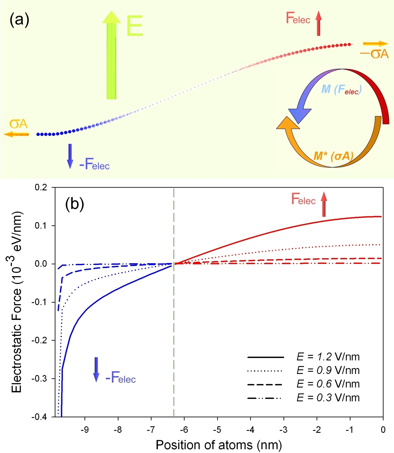
The key to modeling this electromechanical behavior is to understand the force equilibrium in graphene. We consider the force balance in a half GNR as shown in Fig. 2 (a), which highlights the membrane-like character of graphene’s mechanical properties. The formation of a moment of electric force can be understood by results plotted in Fig. 2 (b). This force profile is quite different from a commonly used assumption of a uniform electric force distribution in simplified calculations Fogler et al. (2008); Jonsson et al. (2005). In general, the amplitude of driving electric force should be proportional to either the polarizability of GNR (), or the square of field strength () Kozinsky and Marzari (2006). Since the longitudinal polarizability of graphene is usually much larger than the transverse one Brothers et al. (2005) (), created in each half of the graphene by a electric force distribution (Fig. 2 (b)) can be calculated analytically as
| (2) |
where stands for the angle of deflection (Fig. 1 (a)). In our earlier work Wang (doi: 10.1016/j.carbon.2009.07.026), it has been shown that of a GNR is roughly proportional to its width or the square of its length when the graphene sheet is not too small. Thus, for the system that we study here, Eq. 2 leads to
| (3) |
where nm is a constant related to the dielectric constant of graphene.
We now estimate the moment of membrane force induced by the graphene shape change during the deflection. Considering the fact that graphene’s stiffness in its atomic plane is about 30 times higher than that in the perpendicular direction Bosak et al. (2007); Lee et al. (2008), the internal stress in a curved GNR can be supposed to be mainly due to its axial deformation , which can be approximated as : . Thus, can be expressed as
| (4) |
where is Young’s modulus and is the cross sectional area. Here we use the value of their product eV/nm recently measured from nanoindentation experiments Lee et al. (2008). This value is in good agreement with that from theoretical calculations Shenoy et al. (2008) for GNRs with either armchair or zigzag edges. With the aid of moment balance in graphene (shown in Fig. 2 (a)), and by combining Eqs. 3 and 4, we obtain the governing equation of electrostatic deflection of suspended graphene as follows:
| (5) |
where is a constant. Since has been eliminated from this equation, we can first conclude that the deflection of a GNR is independent of its width. We note that increase of with decreasing can be expected for narrow GNRs due to the effects of depolarization and edge states. However, this variation can be neglected for the size of GNRs usually reported in experiments. This equation also suggests that, for a given deformation angle , required field strength decreases linearly with increasing the square root of graphene length . It is important to note that, since the parameters of our charge-dipole model were fitted for metallic system, Eq. 5 may not be useful for very narrow graphene sheets (with the minimum lateral dimension nm) which have large band gaps due to edge states Ritter and Lyding (2009); Son et al. (2006a).
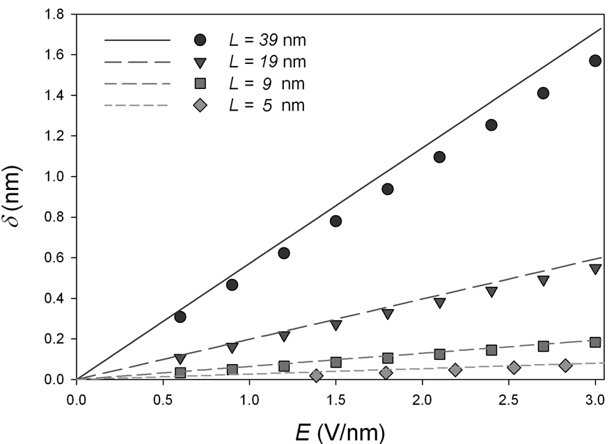
We now consider a particular case of small deflection (typically ), for mainly covering experimentally reported resonance amplitude Bunch et al. (2007); Sazonova et al. (2004). In such a case Eq. 5 implies that is roughly proportional to since geometric simplification gives . The maximal deflection (Fig. 1 (a)) can be approximately calculated as: . Thus, the case of small deflection from Eq 5 leads to
| (6) |
The analytical model presented in Eq. 6 is validated through series of molecular simulations for GNRs of different lengths. Results shown in Fig.3 remark a quantitative agreement between analytical prediction and simulation data. It can be seen that roughly follows a linear relationship with and rapidly increases with , as predicted by Eq. 6. The slight difference between the slopes of the curves is supposed to be mainly due to geometric approximations and the difference between experimentally measured Young’s modulus and the one predicted from simulations.
We now estimate the possibility of graphene’s free oscillation induced by this electrostatic deflection by means of MD. In such simulations we apply a transverse electric field to deflect a suspended GNR, then the field is removed for inducing free oscillation of the GNR around its equilibrium position Sazonova et al. (2004). We simulated the vibration of graphene during a period of time (some ns), and we counted the number of oscillation from the output of the simulations. We found that the GNR oscillates with different harmonics, depending on its length. Only short GNRs ( nm) were observed to oscillate at fundamental harmonic and other GNRs oscillate at high-order ones. This is because the field-induced resonance in a GNR is a combination of transverse and longitudinal waves (see MD simulation video-recording Ritter and Lyding (2009)), while the longitudinal wave has no space to propagate in very short graphene hence only the fundamental harmonic was observed. We note that the vibration mode and frequency can also vary with the initial tension from supports due to different nature of fixation Garcia-Sanchez et al. (2008).
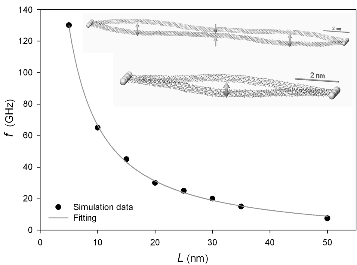
We measured the natural frequency of GNRs with different sizes. From Fig. 4 we can see that decreases rapidly with increasing . This length dependence is comparable to those found for single-walled CNTs Li and Chou (2003). In general, graphene’s free oscillation is tunable by applying an alternating voltage, by which the mechanical vibration can be either enhanced or attenuated in terms of adjusting the AC frequency Sazonova et al. (2004). Theoretically speaking, the suspended structure could even be destroyed if the gate frequency is close to the natural frequency of the graphene.
In conclusion, we have demonstrated that a suspended GNR can be deflected by applying a transverse electric field. The strong correlation between the field strength, graphene size and induced deflection has been concluded in an analytical model, which is validated via simulations. It was found that the deflection of GNRs is roughly proportional to the field strength for small deformations, and increases with the graphene length. The graphene’s resonance frequency induced by this electrostatic deflection is found to decrease dramatically with the graphene length. These results suggest new potential applications of GNRs in electromechanical resonators or oscillators, which allow direct conversion from electric potential energy to mechanical energy in nanoscale.
Acknowledgments
We gratefully thank S. J. Stuart and R. Langlet for their help in the implementation of our computational code. D. Stewart, L. Henrard, A. Mayer, M. Devel and W. Ren are acknowledged for useful discussions.
References
- Castro Neto et al. (2009) A.H. Castro Neto, F. Guinea, N.M.R. Peres, K.S. Novoselov, and A.K. Geim, Rev. Mod. Phys. 81, 109 (2009).
- Beenakker (2008) C.W.J. Beenakker, Rev. Mod. Phys. 80, 1337 (2008).
- Novoselov et al. (2004) K.S. Novoselov, A.K. Geim, S.V. Morozov, D. Jiang, Y. Zhang, S.V. Dubonos, I.V. Grigorieva, and A.A. Firsov, Science 306, 666 (2004).
- Han et al. (2007) M.Y. Han, B. Ozyilmaz, Y. Zhang, and P. Kim, Phys. Rev. Lett. 98, 206805 (2007).
- Son et al. (2006a) Y.W. Son, M.L. Cohen, and S.G. Louie, Phys. Rev. Lett. 97, 216803 (2006a).
- Yang et al. (2007) L. Yang, C.H. Park, Y.W. Son, M.L. Cohen, and S.G. Louie, Phys. Rev. Lett. 99, 186801 (2007).
- Castro et al. (2007) E.V. Castro, K.S. Novoselov, S.V. Morozov, N.M.R. Peres, J.M.B.Lopes dosSantos, J. Nilsson, F. Guinea, A.K. Geim, and A.H. Neto, Phys. Rev. Lett. 99, 216802 (2007).
- Novikov (2007) D.S. Novikov, Phys. Rev. Lett. 99, 056802 (2007).
- Yan et al. (2007) J. Yan, Y. Zhang, P. Kim, and A. Pinczuk, Phys. Rev. Lett. 98, 166802 (2007).
- Bunch et al. (2007) J.S. Bunch, A.M. Van Der Zande, S.S. Verbridge, I.W. Frank, D.M. Tanenbaum, J.M. Parpia, H.G. Craighead, and P.L. McEuen, Science 315, 490 (2007).
- Son et al. (2006b) Y.W. Son, M.L. Cohen, and S.G. Louie, Nature (London) 444, 347 (2006b).
- Poncharal et al. (1999) P. Poncharal, Z. L. Wang, D. Ugarte, and W. A. de Heer, Science 283, 1513 (1999).
- Anantram and Leonard (2006) M.P. Anantram and F. Leonard, Rep. Prog. Phys. 69, 507 (2006).
- Wang and Philippe (2009) Z. Wang and L. Philippe, Phys. Rev. Lett. 102, 215501 (2009).
- Kozinsky and Marzari (2006) B. Kozinsky and N. Marzari, Phys. Rev. Lett. 96, 166801 (2006).
- Lee et al. (2008) C. Lee, X. Wei, J.W. Kysar, and J. Hone, Science 321, 385 (2008).
- Joselevich and Lieber (2002) E. Joselevich and C. M. Lieber, Nano Lett. 2, 1137 (2002).
- Garcia-Sanchez et al. (2008) D. Garcia-Sanchez, A.M. van der Zande, A.S. Paulo, B. Lassagne, P.L. McEuen, and A. Bachtold, Nano Lett. 8, 1399 (2008).
- Stuart et al. (2000) S.J. Stuart, A.B. Tutein, and J.A. Harrison, J. Chem. Phys. 112, 6472 (2000).
- Ni et al. (2002) B. Ni, S.B. Sinnott, P.T. Mikulski, and J.A. Harrison, Phys. Rev. Lett. 88, 205505 (2002).
- Shenoy et al. (2008) V.B. Shenoy, C.D. Reddy, A. Ramasubramaniam, and Y.W. Zhang, Phys. Rev. Lett. 101, 245501 (2008).
- Mayer (2007) A. Mayer, Phys. Rev. B 75, 045407 (2007).
- Wang et al. (2008) Z. Wang, M. Zdrojek, T. Mélin, and M. Devel, Phys. Rev. B 78, 085425 (2008).
- Wang and Devel (2007) Z. Wang and M. Devel, Phys. Rev. B 76, 195434 (2007).
- Guo and Guo (2003) W. Guo and Y. Guo, Phys. Rev. Lett. 91, 115501 (2003).
- Fasolino et al. (2007) A. Fasolino, J.H. Los, and M.I. Katsnelson, Nature Mat. 6, 858 (2007).
- Wang (2009) Z. Wang, Phys. Rev. B 79, 155407 (2009).
- Jonsson et al. (2005) L. M. Jonsson, L. Y. Gorelik, R. I. Shekhter, and M. Jonson, Nano Lett. 5, 1165 (2005).
- Fogler et al. (2008) M.M. Fogler, F. Guinea, and M.I. Katsnelson, Phys. Rev. Lett. 101, 226804 (2008).
- Brothers et al. (2005) E.N. Brothers, K.N. Kudin, G.E. Scuseria, and C.W. Bauschlicher, Phys. Rev. B 72, 033402 (2005).
- Wang (doi: 10.1016/j.carbon.2009.07.026) Z. Wang, Carbon (in press) (doi: 10.1016/j.carbon.2009.07.026).
- Bosak et al. (2007) A. Bosak, M. Krisch, M. Mohr, J. Maultzsch, and C. Thomsen, Phys. Rev. B 75, 153408 (2007).
- Ritter and Lyding (2009) K. A. Ritter and J. W. Lyding, Nature Mat. 8, 235 (2009).
- Ritter and Lyding (2009) See EPAPS Document for a supplementary movie.
- Li and Chou (2003) C. Li and T.W. Chou, Phys. Rev. B 68, 073405 (2003).
- Sazonova et al. (2004) V. Sazonova, Y. Yalsh, I. Ustunel, D. Roundy, T.A. Arlas, and P.L. McEuen, Nature (London) 431, 284 (2004).
I Figures