Spherical cloaking using nonlinear transformations for improved segmentation into concentric isotropic coatings
Cheng-Wei Qiu1,2, Li Hu2, Baile Zhang1, Bae-Ian Wu1, Steven G. Johnson3, and John D. Joannopoulos1
1Research Laboratory of Electronics, Massachusetts Institute of Technology, Cambridge, Massachusetts 02139, USA
cwq@mit.edu
2Department of Electrical and Computer Engineering, National University of Singapore, 4 Engineering Drive 3, Singapore 117576.
3Department of Mathematics, Massachusetts Institute of Technology, Cambridge, Massachusetts 02139, USA
stevenj@math.mit.edu
Abstract
Two novel classes of spherical invisibility cloaks based on nonlinear transformation have been studied. The cloaking characteristics are presented by segmenting the nonlinear transformation based spherical cloak into concentric isotropic homogeneous coatings. Detailed investigations of the optimal discretization (e.g., thickness control of each layer, nonlinear factor, etc.) are presented for both linear and nonlinear spherical cloaks and their effects on invisibility performance are also discussed. The cloaking properties and our choice of optimal segmentation are verified by the numerical simulation of not only near-field electric-field distribution but also the far-field radar cross section (RCS).
OCIS codes: (290.5839) Scattering, invisibility; (160.1190) Materials: Anisotropic optical materials; (230.3205) Invisibility cloaks
References and links
- [1] J. B. Pendry, D. Schurig, and D. R. Smith, “Controlling electromagnetic fields,” Science 312, 1780 (2006).
- [2] D. Schurig, J. B. Pendry, and D. R. Smith, “Calculation of material properties and ray tracing in transformation media,” Opt. Express 14, 9794-9804 (2006). U. Leonhardt,
- [3] U. Leonhardt,“Optical conformal mapping,” Science 312, 1777-1780 (2006).
- [4] D. Schurig, J. B. Pendry, and D. R. Smith, “Transformation-designed optical elements,” Opt. Express 15, 14772-14782 (2007).
- [5] A. Greenleaf, M. Lassas, and G. Uhlmann, “Anisotropic conductivities that cannot be detected by EIT,” Physiol. Meas. 24, 413-419 (2003).
- [6] H. Chen and C. T. Chan, “Acoustic cloaking in three dimensions using acoustic metamaterials,” Appl. Phys. Lett. 91, 183518 (2007).
- [7] H. Chen, B. I. Wu, B. Zhang, and J. A. Kong, “Electromagnetic Wave Interactions with a Metamaterial Cloak,” Phys. Rev. Lett. 99, 063903 (2007).
- [8] B. Zhang, H. Chen, B. I. Wu, and J. A. Kong, “Extraordinary Surface Voltage Effect in the Invisibility Cloak with an Active Device Inside,” Phys. Rev. Lett. 100, 063904 (2008).
- [9] M. Rahm, D. Schurig, D. A. Roberts, S. A.Cummer, and D. R. Smith, “Design of electromagnetic cloaks and concentrators using form-invariant coordinate transformations of Maxwell’s equations,” Photonics Nanostruc. Fundam. Appl. 6, 87 (2008).
- [10] D. Kwon and D. H. Werner, “Two-dimensional eccentric elliptic electromagnetic cloaks,” Appl. Phys. Lett. 92, 013505 (2008).
- [11] W. X. Jiang, T. J. Cui, G. X. Yu, X. Q. Lin, Q. Cheng and J. Y. Chin, “Arbitrarily elliptical Ccylindrical invisible cloaking,” J. Phys. D: Appl. Phys. 41, 085504 (2008).
- [12] M. Yan, Z. Chao, and M. Qiu, “Cylindrical invisibility cloak with simplified material parameters is inherently visible,” Phys. Rev. Lett. 99, 233901 (2007).
- [13] M. Yan, Z. Chao, and M. Qiu, “Scattering characteristics of simplified cylindrical invisibility cloaks,” Opt. Express 15, 17772 C17782 (2007).
- [14] H. Ma, S. B. Qu, Z. Xu, J. Q. Zhang, B. W. Chen, and J. F. Wang, “Material parameter equation for elliptical cylindrical cloaks,” Phys. Rev. A 77, 013825 (2008).
- [15] W. Cai, U. K. Chettiar, A. V. Kildishev, and V. M. Shalaev, “Optical cloaking with metamaterials,” Nat. Photonics 1, 063904 (2007).
- [16] B. Zhang, H. Chen, and B. I. Wu, “Limitations of high-order transformation and incident angle on simplified invisibility cloaks,” Opt. Express 16, 5445-5452 (2008).
- [17] D. Schurig, J. J. Mock, B. J. Justice, S. A. Cummer, J. B. Pendry, A. F. Starr, and D. R. Smith, “Metamaterial electromagnetic cloak at microwave frequencies,” Science 314, 977 (2006).
- [18] R. Liu, C. Ji, J. J. Mock, J. Y. Chin, T. J. Cui, and D. R. Smith, “Broadband Ground-Plane Cloak,” Science 323, 366–369 (2009).
- [19] W. X. Jiang, J. Y. Chin, Z. Li, Q. Cheng, R. Liu, and T. J. Cui, “Analytical design of conformally invisible cloaks for arbitrarily shaped objects,” Phys. Rev. E 77, 066607 (2008).
- [20] H. Ma, S. Qu, Z. Xu, and J. Wang, “Numerical method for designing approximate cloaks with arbitrary shapes,” Phys. Rev. E 78, 036608 (2008).
- [21] A. Nicolet, F. Zolla, and S. Guenneau, “Electromagnetic analysis of cylindrical cloaks of an arbitrary cross section,” Opt. Lett. 33, 1584 (2008).
- [22] C. W. Qiu, L. W. Li, T. S. Yeo, and S. Zouhdi, “Scattering by rotationally symmetric anisotropic spheres: Potential formulation and parametric studies,” Phys. Rev. E 75, 026609 (2007).
- [23] W. Cai, U. K. Chettiar, A.K. Kildishev, G. W. Milton, and V. M. Shalaev, “Non-magnetic cloak without reflection,” arXiv:0707.3641v1.
- [24] R. Weder, “A rigorous analysis of high-order electromagnetic invisibility cloaks,” J. Phys. A: Math. Theor. 41, 065207 (2008).
- [25] C. W. Qiu, L. W. Li, Q. Wu, and T. S. Yeo, “Field representations in general gyrotropic media in spherical coordinates,” IEEE Antennas Wirel. Propagat. Lett. 4, 467-470 (2007).
- [26] C. W. Qiu, S. Zouhdi, and A. Razek, “Modified spherical wave functions with anisotropy ratio: Application to the analysis of scattering by multilayered anisotropic shells,” IEEE Trans. Antennas Propagat. 55, 3515-3523 (2007).
- [27] J. C. E. Sten, “DC fields and analytical image solutions for a radially anisotropic spherical conductor,” IEEE Trans. Diel. Elec. Insul. 2, 360-367 (1995).
- [28] B. I. Popa and S. A. Cummer, “Cloaking with optimized homogeneous anisotropic layers,” Phys. Rev. A 79, 023806 (2009).
- [29] C. W. Qiu, L. Hu, L. Gao, “Trade-off between forward and backward scatterings of Linear and Nonlinear Spherical Invisibility Cloaks,” Progress In Electromagnetics Research, to be submitted (2009).
1 Introduction
The use of coordinate transformation to control electromagnetic fields [1] has been receiving extensive attention [2, 3, 4]. This approach was generalized from the cloaking of thermal conductivity [5], and was further widely applied in electromagnetics and acoustics [1, 6], which provides new ways to conceal passive/active objects [7, 8] within their interiors invisible to external illuminations. The fundamental idea is that Maxwell’s equations are invariant under a coordinate transformation if the material properties (electric permittivity and magnetic permeability) are altered appropriately; i.e., a specific spatial compression is equivalent to a variation of the material parameters in flat (original) space. Cloaks in regular shapes (e.g., spherical [1], square [9], cylindrical [10], or elliptic [11]) have been proposed based on the construction of explicit transformation matrices. There are many works devoted to the investigation of 2D cylindrical/elliptic cloaks approximated by, for example, simplified material parameters or equations [12, 13, 14, 15], or designed for limited incident angles [16]. Experimental investigations of 2D cloaks have demonstrated significant reductions in the scattering cross section, albeit for narrow bandwidths in the microwave regime and for objects at most a few wavelengths in diameter so far [17]. Broader bandwidths have been demonstrated for cloaking an object on a ground plane, but again only for a few wavelengths diameter [18]. To design irregularly shaped cloaks, both analytical [19] and numerical methods [20, 21] have been proposed. In what follows, we will confine our discussion within the area of 3D electromagnetic spherical cloaks.
Inspired by the classic spherical cloak [1] based on a linear coordinate transformation, the expressions of electromagnetic fields were explicitly presented in terms of spherical Bessel functions along the lines of Mie scattering theory [7], and it again was demonstrated that the external incident wave cannot interact with the cloaked object in a perfect spherical cloak. Linear coordinate transformations correspond to a transverse/radial permittivity ratio (anisotropy ratio [22]) , where is the radius of the cloaked region. The subtle point of the singularity in the coordinate transformation at the innner surface of the cloak was analytically shown to correpond to surface voltages [8] in spherical cloaks, leading to an explicit physical explanation for why the wave cannot leave the cloaked region and external waves cannot enter that region. These works on spherical cloaks considered linear coordinate transformations, while more recently nonlinear (“high-order”) transformations have been considered in order to obtain more degrees of freedom in designing the material parameters [23, 24]. In this paper, we consider the utility of nonlinear coordinate transformations to improve the performance of the cloak when it is approximated (segmented) into a sequence of piecewise-homogeneous layers. If the anisotropy ratio differs from , it will lead to quite complicated formulations for the field expressions, which cannot be treated by the previous method for a position-dependent anisotropy ratio [7] or by the method for a constant anisotropy ratio [25, 26]. Here, in order to study the proposed nonlinear-transformation spherical cloaks, each anisotropic cloaking shell is discretized into multiple alternating homogeneous isotropic coatings, not only for the ease of fabrication but also for the computation convenience in dealing with arbitrary anisotropy ratios.
In general, practical implemenations of passive invisibility cloaks by coordinate transformation are limited by several factors, in addition to the bandwidth limitations (from material dispersion) mentioned above. First, there are fabrication imperfections and the finite size of the subwavelength components of the metamaterials. Second, there is material absorption, which is especially challenging when an extreme resonant response is required of the material in order to obtain very large or very small permittivity/permeability. Third, there is the difficulty of fabricating continuously varying anisotropic materials. In this paper, we focus only on the third issue. A common approximation for continuously varying materials is to segment them into piecewise-homogeneous layers, and we show that the choice of coordination transformation has a significant impact upon the success of this approximation. We argue that the segmentation is best performed in virtual space rather than in the physical (transformed) coordinates. We also demonstrate that the anisotropic materials can be further approximated by a sequence of isotropic-material layers. The optimal selection of material parameters, nonlinear transformation, and segmentation (in virtual space), in order to achieve a low scattering cross sectikon over a wide range of observation angles, is found for nonlinear spherical cloaks and verified by numerical results.
2 Preliminaries
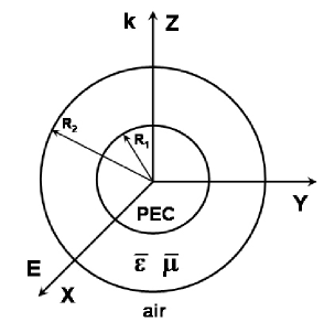
The configuration of the spherical cloaking structure is shown in Fig. 1. The inner region () is a perfect electric conductor (PEC) and the intermediate region () is filled by the nonlinearly transformed spherical cloak, characterized by and , which will be discussed below. The electric field is polarized along the axis and propagating along the axis.
By applying the decomposition method and separation of variables [22], the equation for the radial component of the field potentials becomes
| (1) |
where the subscripts and denote the electric and magnetic anisotropic ratio, respectively, and [22]. For and of perfect linear spherical cloaks [1], i.e., , Eq. (1) is reduced to
| (2) |
Thus, the radial component can be solved in a way similar to that for isotropic materials, except for the change in the argument of resultant Bessel/Hankel functions. However, given a set of and derived from a certain transform, the anisotropy ratio may not be anymore, and then the radial component cannot be solved explicitly in the same way. In this situation, we could approximate the original inhomogeneous anisotropic cloak by many thin, homogeneous anisotropic coatings, and the diffraction problem can thus be solved in terms of analytical Bessel/Hankel functions satisfying boundary conditions at each interface. Nevertheless, the requirement of anisotropic materials still remains. Alternatively, to further alleviate the restriction in material complexity, the original inhomogeneous anisotropic cloaking materials can be approximated by the limit of many thin, concentric, homogeneous, isotropic coatings, forming an effective anisotropic medium, which will be discussed in this section.
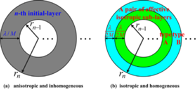
First, we consider a general spherical cloak characterized by and , in which and are position-dependent in general. It is then divided into initial-layers (anisotropic) but the thickness of individual initial layers may or may not be identical, depending on the transformation. Given a coordinate transformation function between the virtual space (i.e., , ) and the compressed space (i.e., , ), the stepwise segmentation in physical space () is desired to mimic the transformation function as well as possible and we also desire that the segmentation not be too complicated. We find that equally dividing the virtual space () into initial-layers will make the segmentation on the physical space () “self-adaptive” in a simple way—it automatically uses a finer discretization in regions of physical space where the anisotropic materials are varying more rapidly—which will result in better invisibility performance. This conversion is illustrated in Fig. 2. Throughout this paper, we apply the same condition, i.e., the segmented layers in are of equal thickness, which represents a good choice of segmentation in the initial-layers in the cloak shell . By projecting the segmentation in onto the physical , one has . Thus, the geometry of every initial-layer in Fig. 2(a) is determined.
Subsequently, we mimic each spherically anisotropic initial layer by a pair of effective isotropic sub-layers (type-A and type-B) with equal thickness at , as shown in Fig. 2(b). The material parameters of type-A and type-B isotropic dielectrics can be inferred and derived from the result for radial conductivity by Sten [27]:
| (3a) | |||
| (3b) | |||
Now, the original spherical cloak turns to be a concentric isotropic coatings. Throughout this paper, and are chosen in order that the validity of Eq. (3) can be maintained, i.e., sub-layers have to be sufficiently thin. Alternatively one could also choose a smaller associated with the corresponding parameters determined by optimization methods and then subdivide each anisotropic layer into many more than two isotropic sub-layers.
When converting the -th initial layer into its pair of effective isotropic sub-layers, we need to pick a specific radial position for those and on the right-hand side of Eq. (3) within the initial layer in order to determine corresponding parameters of the two isotropic dielectrics (, ) and (, ) on the left-hand side of Eq. (3) and in Fig. 2(b). According to [29], such a discretization mechanism using in Eq. (3) for the -th initial layer will give a good compromise for both forward and backward scatterings, while retaining good invisibility performance.
3 Effects of Nonlinear Transformation in Nonlinear Spherical Cloaks
Pendry’s spherical cloak [1] is a linear one, and hence it is a straight line if one plots the transformation function against the physical radius . In what follows, we introduce two classes of nonlinear-transformation spherical cloaks, and we discuss how to restore and improve the invisibility performance after discretization by choosing a proper nonlinear transformation and by choosing a suitable compensation scheme while discretizing the original spherical cloak into multilayer isotropic structures. The two types of spherical cloaks considered here are classified in terms of the negative (i.e., concave-down) or positive (i.e., concave-up) sign of the second derivative of the transformation function. It is important to reiterate that all three designs—linear, concave-up, and concave-down—are perfect cloaks for the exact inhomogeous design, and we are only considering the breakdown of invisibility when the design is discretized into homogeneous layers.
3.1 Concave-Down Nonlinear Transformation
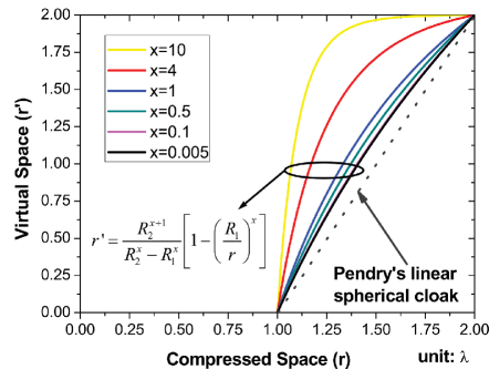
To compress a sphere of air at the radius in (original) space into a shell at the region in (compressed) space, we propose a class of prescribed functions
| (4) |
where denotes the degree of the nonlinearity in the transformation. When is very small in Eq. (4), the curves are difficult to distinguish and all approach to the same limiting case when :
| (5) |
Thus the parameters in the transformed coordinates can be written in term of in the original space by
| (6) |
where is the Jacobian matrix with elements defined as .
Note that all curves belonging to those transformation functions in Eq. (4) have negative second derivative with respect to the physical space , and we term this class of transformations the concave-down nonlinear transformation. The nonlinear transformation function in Eq. (4) only depends on the radial component in the spherical coordinate system . Thus it is easy to find that the Jacobian matrix is diagonal. Considering that the original space is filled with air (), Eq. (6) can be rewritten as
| (7) |
where
| (8a) | |||||
| (8b) | |||||
denoting three principal stretches of the Jacobian matrix. Finally, the desired parameters in the compressed space () are shown to be
| (9a) | |||||
| (9b) | |||||
Given such radial and transversal parameters, it is obvious that Eq. (1) cannot be simply solved due to the complicated anisotropy ratio in our current case. In addition, one can also find that when the virtual space is equally discretized using a concave-down nonlinear transformation, the segmentation of the initial layers in Fig. 2 in the physical space is
| (10) |
in all
regions on x-z plane
outside
the cloak on x-z
plane
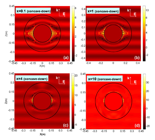
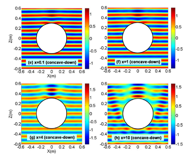
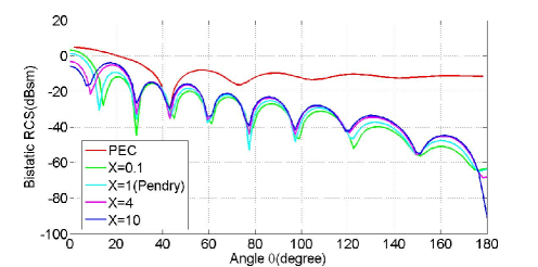
Here, we will study the effects of the nonlinear factor in the near-field and far-field of the discretized nonlinear-transformation spherical cloaks. We fix M=40, and consider the cases of x=0.1, x=1, x=4, and x=10 in concave-down nonlinear cloaks, shown in Fig. 4. It can be seen from Figs. 4(a-d) that when increases, the magnitude of electric field increases significantly inside the cloak. This is because more energy is guided towards the inner boundary of the PEC core, which in turn makes the cloaked PEC more visible to external incidences. To prove that the large electric fields only occur in the region and to study the effect of on individual near-field perturbations more explicitly, only the fields outside the cloak are presented in Figs. 4(e-f). One can again confirm that, for discretized concave-down nonlinear spherical cloaks, smaller leads to smaller disturbance in electric fields in the outer space. In particular, the degradation in the invisibility in the forward direction is proportional to the value of (see Fig. 4(g) and Fig. 4(h)).
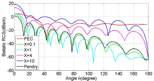
In Fig. 5, we consider the far fields of those cases of Fig. 4. For comparison purposes, we introduce two more curves, PEC and Pendry’s cloak. It should be noted that the curve corresponding to Pendry’s cloak is a straight line, and the same segmentation procedure as discussed above is applied to it, which is the same as equally dividing it into initial-layers in the physical space (see Fig. 3). From Fig. 5, it can be seen that for concave-down nonlinear transformations, the cloaking property is better retained when is small. Except for the forward direction, concave-down nonlinear transformation with small can achieve even lower RCS over a wide range of observation angles. As keeps increasing, their RCSs are increasing dramatically and can be larger than that of a uncloaked PEC core (e.g., ). No matter how large becomes, the suppressed backward scattering is still maintained [7] though it is not exactly zero due to the discretization, but the forward scattering will become higher and higher, which is not desired in the cloaking application. Those far-field characteristics are consistent with the perturbation in corresponding near-field patterns in Fig. 4.
3.2 Concave-Up Nonlinear Transformation
We can also propose another class of prescribed functions
| (11) |
It is found that when , it also approaches to the same limit as Eq. (5). In the same manner, we can obtain the desired parameters in the compressed space ()
| (12a) | |||||
| (12b) | |||||
Note that the case is exactly Pendry’s linear spherical cloak.
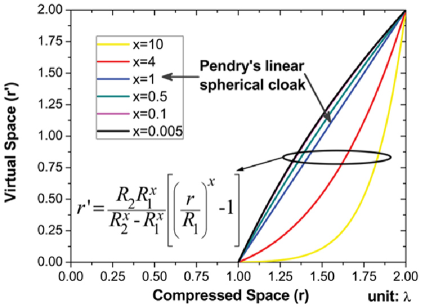
It can be seen in Fig. 6 that all curves belonging to Eq. (11) have positive second derivatives, and we term this class of transformations as the concave-up nonlinear transformations. Also, it is found that the limiting case of Eq. (5), i.e, , is the dividing line between the convace-down and concave-up classes. Since in Eq. (11) is actually very close to the situation of for concave-down nonlinear transformations, we will not revisit that case here. Instead, we only consider , , and concave-up transformations [Eq. (12)], and the segmentation for concave-up nonlinear spherical cloaks in physical space turns out to be
| (13) |
We are interested to see which class will give rise to better invisibility performance, after discretization, if all the other conditions are the same. We still plot the near field of concave-up cloaks at “x=1”, “x=4”, and “x=10”. Comparing Fig. 4 with Fig. 7, one can see that: (1) the peak amplitude of the electric field is proportional to in both classes; (2) for each value of , concave-up transformation cloaks have lower peak amplitudes than concave-down transformation cloaks, i.e., the perturbation inside the cloak region is smaller; (3) the perturbation outside the cloak of concave-up transformation cloaks is also lower than that of concave-down transformation cloaks in all cases of ; (4) the invisibility performance is better maintained for concave-up transformations even when or even larger. Hence, spherical cloaks based on concave-up nonlinear transformations exhibit better invisibility after discretization.
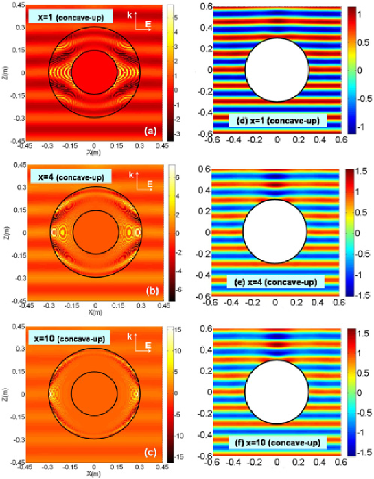
Fig. 8 exhibits some interesting features which distinguish it from the far fields of concave-down transformations in Fig. 5. Over a wide range of angles, the invisibility performance of spherical cloaks based on concave-up nonlinear transformations are more stable under variations in . More importantly, when increases (e.g., or ), though the RCS will be a bit larger than Pendry’s linear cloak at most angles, the RCS near the forward direction will be reduced greatly compared with that of classic linear cloak. Such far-field phenomena are also connected with the near-field patterns. It is important to point out that the increase of in concave-up transformations [see Figs. 7(a–c)] will push the “hot” areas (where the electric field is very high) further and further away from the spherical PEC core, so the induced shadow and the far-field pattern become stable with increasing . However, the increase of in the concave-down transformations has little effect in shifting away the “hot” positions from the core [see Fig. 4(a–d)], which results in larger interaction with the PEC core. Hence, the RCS reduction in the far field is degraded with the increase of in the concave-down class as shown in Fig. 5.
4 Justification of Improved Segmentation
It has been pointed out that usually we require a large value of during the discretization process, otherwise the conversion scheme in Fig. 2 will lose its accuracy. We also find that a nonlinear transformation with a given of its concave-up class will yield a better invisibility by taking the segmentation as Eq. (13) in the physical space (this is also the only way to determine sub-layers of type-A and type-B dielectrics in practice). Here the justification is given. The concave-up class with , which is characterized by the mapping curve , is considered as an example.
. ∗ Note that for concave-up cloaks corresponds to the case of equally dividing the physical space.
In Table I, different segmentation sets (see Eq. 13) for real radius are applied to , e.g., the sets of (), (), () and (). The total cross sections corresponding to those four sets are compared with the best segmentation set of its own , i.e., equally dividing the virtual space of into 40 initial-layers and then projecting onto physical space. We find that, for concave-up class , is indeed its optimal segmentation among these possibilities.
5 Conclusion
In this paper, we discussed two novel classes of nonlinear-transformation–based spherical cloaks. An approximation mechanism for such classes of spherical cloaks by concentric isotropic sub-layers is proposed. The optimal segmentation in the virtual space is presented, and the role of nonlinearity in the coordinate transformation is discussed in order to provide better invisibility performance for the proposed classes of nonlinear spherical cloaks in both the near and far field. We find that concave-up nonlinear-transformation spherical cloaks exhibit better and more stable invisibility performance than the corresponding segmentation of linear-transformation or concave-down cloaks. An interesting topic for future exploration would be to consider a wider class of segmentation schemes, for example by using the segmentation presented here as the starting point for a numerical optimization (e.g., Ref. [28] for cylindrical cloaks) of variable segment thicknesses and material parameters.
6 Acknowledgement
This research was supported in part by the Army Research Office through the Institute for Soldier Nanotechnologies under Contract No. W911NF-07-D-0004.