Ultra-broadband photon pair preparation by spontaneous four wave mixing in dispersion-engineered optical fiber
Abstract
We present a study of the spectral properties of photon pairs generated through the process of spontaneous four wave mixing (SFWM) in single mode fiber. Our analysis assumes narrowband pumps, which are allowed to be frequency-degenerate or non-degenerate. Based on this analysis, we derive conditions on the pump frequencies and on the fiber dispersion parameters which guarantee the generation of ultra-broadband photon pairs. Such photon pairs are characterized by: i) a very large degree of entanglement, and ii) a very high degree of temporal synchronization between the signal and idler photons. Through a numerical exercise, we find that the use of photonic crystal fiber (PCF) facilitates the fulfilment of the conditions for ultra-broadband photon pair generation; in particular, the spectral region in which emission occurs can be adjusted to particular needs through an appropriate choice of the PCF parameters. In addition, we present a novel quantum interference effect, resulting from indistinguishable pathways to the same outcome, which can occur when pumping a SFWM source with multiple spectral lines.
pacs:
42.50.-p, 03.65.Ud, 42.65.HwI Introduction
Quantum-enhanced technologies require photon pairs with specific properties. Thus, for example, factorability is required for the generation of pure heralded single photons, a crucial resource for linear optical quantum computationuren05 . At the opposite extreme, spontaneous parametric processes permit the generation of photon pairs with a remarkably large degree of entanglement. Such photon pairs are characterized by a large Schmidt numbercklaw00 , which implies that emission takes place into a large number of independent frequency or transverse momentum signal and idler mode pairs. A state with these characteristics leads to a large mutual information, which quantifies the information which two parties can in principle share by virtue of the entanglement presentzhang07 . Two-photon states with a large degree of entanglement may lead to exciting applications, such as large-alphabet quantum key distributionaKhan07 , quantum-enhanced two photon absorptionDayan04 , and teleportation of single-photon wavepacketsmolotkov .
Most research on photon pair generation has relied on the process of spontaneous parametric downconversion (PDC) in second-order non-linear crystalsburnham70 . Recently, the process of spontaneous four-wave-mixing (SFWM) in optical fiber, relying on a third-order non-linearity, has emerged as a useful alternative, with some clear advantages. Indeed, fibers permit an essentially unlimited interaction length; in addition, the generated flux is proportional to the square of the pump power, instead of the linear pump-power dependence observed for PDC. This leads to the possibility of remarkably bright sources. While some of the first SFWM experiments were carried out with standard telecom fiberwang01 , recent experiments have exploited the greater flexibility conferred by photonic crystal fibers (PCF) sharping04 . Thus, for example, the zero group velocity dispersion frequencies may be selected by careful choice of the fiber design parameters, leading to the ability to also select the generation frequencies. In previous work, we have showngaray07 that SFWM in PCF’s leads to the ability to engineer the spectral entanglement properties of photon pairs.
We are particulary interested in spontaneous parametric processes constrained to a single transverse mode, e.g. in a single-mode waveguide or fiber. Under these circumstances transverse momentum entanglement as well as mixed spectral-transverse momentum entanglement are automatically suppressed. Thus, for single-transverse-mode parametric processes we may limit our analysis of the entanglement present to the spectral degree of freedom. It has been shown that a large Schmidt number can then be obtained by engineering the photon pair generation process to yield the largest possible emission bandwidth compatible with the smallest possible pump bandwidthzhang07 . Apart from its role in enhancing the attainable degree of entanglement, a large generation bandwidth also leads to a small correlation time, defined as the width of the time of emission difference (between signal and idler) probability distributionHarris07 ; Strekalov05 . A source with these characteristics would be useful for applications relying on a short time of arrival difference between two optical modes, such as quantum optical coherence tomographynasr03 where the instrument resolution is inversely proportional to the correlation time. Let us note that an ultra-broadband photon pair source treated classically, i.e. where we employ standard non-photon-counting detectors, could serve as a substitute for white light sources (e.g. based on self-phase modulation in fibers) with one clear advantage: while white light spectra often have a rather irregular shape, ultra-broadband parametric processes can be engineered to have a nearly flat spectrum. Likewise, a source with these characteristics could lead to parametric amplifiers with an exceptionally large bandwidth.
The generation of ultra-broadband two-photon states is possible with sources based on parametric downconversion (PDC) relying on second-order non-linear crystalsNasr05 ; Carrasco06 ; nasr08 ; hendrych08 . In a recent experiment, it was shown that selecting the non-linear crystal and pump frequency so that the emitted light is centered at the zero group velocity dispersion frequency of the non-linear medium leads to PDC light with a remarkably broad spectrum; a full width at half maximum generation bandwidth of m centered at m was demonstratedodonnell07 . Nevertheless, an important limitation of an approach based on PDC, is that because broadband emission occurs at the zero dispersion frequency, the central emission frequency cannot be freely selected. Note that while periodic poling in non-linear crystalsfejer92 can be exploited to yield phase-matching at arbitrary wavelengths, it cannot be used to manipulate the zero dispersion frequency, and hence to select the ultra-broadband central frequency; thus, the experiment discussed above operates in a spectral region which is inconvenient for many applications. This leads to the motivation for the present work, in which we aim to develop fiber-based ultra-broadband photon pair sources, with far greater freedom for selecting the central generation frequency and other emission characteristics.
In this paper we analyze the spectral properties of photon pairs generated through the process of spontaneous four wave mixing (SFWM) in optical fiber. We concentrate on the case of quasi-monochromatic pumps which may be either frequency degenerate or non-degenerate, and where all the fields propagate in the fundamental fiber mode. While our theory can be applied to any fiber, we illustrate our discussion with a numerical exercise for the specific case of photonic crystal fiber, composed of a solid core and a cladding with an array of air holes. The main motivation for using PCF is that the resulting dispersion properties can be tailored by careful choice of the fiber design parameters including the size, location and shape of the air holes, which in turn permits the generation of photon pairs with tailored properties. We analyze the conditions which must be imposed on the pump frequencies and the fiber parameters to permit ultra-broadband photon pair generation. Note that while broadband four-wave-mixing in optical fiber has been analyzed from a classical perspective by several groupsmarhic96 , such an analysis has not been presented for the spontaneous, non-classical case. We also discuss a quantum interference effect which can occur in the process of SFWM when the pump includes multiple spectral lines, for example corresponding to degenerate and non-degenerate pumps.
II Spontaneous four wave mixing theory
We study the spontaneous four wave mixing process in single-mode fiber with a third-order nonlinearity . In this process, a photon pair, comprised of one photon in the signal mode, , and one photon in the idler mode , is created by joint annihilation of two photons from the pump fields and . In this paper we focus on source geometries which permit the generation of particularly broadband signal and idler photon-pair states. Remarkably, this is possible even if the pumps are nearly monochromatic. Our theory in this paper is valid in the limit of monochromatic pumps, and for all generation frequencies. In contrast, the theory presented in a related paper from our groupgaray07 for broadband pumps, is valid only for a narrow signal and idler spectral vicinity and is therefore unsuitable for the description of broadband photon-pair generation. In our present analysis we assume that all fields are co-polarized and that they propagate in the fundamental transverse mode of the fiber.
The quantum state of the generated photon pair in an optical fiber of length can be obtained following a standard perturbative approach mandel and is given by
| (1) |
where is a constant which represents the generation efficiency and is the joint spectral amplitude function (JSA), which describes the spectral entanglement properties of the photon pair
| (2) |
The JSA function is given in terms of the phasemismatch function
| (3) |
which includes self/cross-phase modulation contributions for the two pumps with peak powers and , characterized by the nonlinear parameters and ; (with ) represents the spectral shape of the pumps. The energy conservation constraint is apparent in the argument of the second term of the phase mismatchgaray07 .
II.1 Spontaneous four-wave mixing with narrowband pumps
An expression for the JSA (Eq.( II)) in closed analytic form, valid for all generation frequencies, can be derived if both pumps are nearly monochromatic. Here we assume that the pumps have a Gaussian spectral profile, centered at frequencies and , each with a narrow bandwidth . It can be shown that in the limit where both pumps are monochromatic, i.e. , the product of the two pump envelope functions in Eq.(II) reduces to
| (4) |
The appearance of a Dirac delta function involving in Eq.(II.1) allows us to carry out the integral in Eq.(II). Thus, in the limit of monochromatic pumps, the JSA is given by
| (5) |
in terms of a normalization constant and the phase mismatch which is now a function only of and
| (6) |
| (7) |
where
| (8) |
in terms of
| (9) |
Note that while represents the joint spectrum, represents the singles spectrum. From Eq.(II.1), it is clear that photon-pair generation requires the fulfilment of the following two conditions: i) energy conservation, or and ii) momentum conservation or , with a tolerance which is inversely proportional to . In order to analyze the phase matching properties near the zero group velocity dispersion frequency of the fiber, we express the propagation constant as a Taylor series centered at . Thus, the phasemismatch may be expressed to fourth order as
| (10) |
where , where represents the th frequency derivative of evaluated at , and where represents the th frequency derivative of evaluated at . Here, we have defined detunings with respect to , and furthermore have defined new variables given by the sum and difference of these detunings
| (11) |
Let us note that the constant term of the expansion, , vanishes if perfect phasematching is achieved for pump frequencies and at the generated frequencies and . The JSA can then be written as
| (12) | |||||
where we have defined .
II.2 Step index dispersion model for photonic crystal fiber
Our analysis so far, and the conditions for ultrabroadband photon pair generation to be presented in Sec. III, are valid for any fiber. In order to carry out specific numerical calculations, in this paper we use specialize our discussion to photonic crystal fiber. This type of fiber consists of a fused silica core surrounded by silica cladding with a pattern of air holes which remains constant along the fiber length. This mixture of air and and glass in the cladding results in an average refractive index that is considerably lower than that of the core, providing a high dielectric contrast, resulting in strong optical confinement. This leads to high peak irradiances even for modest input powers, which enhances nonlinear optical effects such as SFWM. In addition, the dispersion characteristics of the PCFs can be engineered by variations of the distribution, size and shape of the air holes surrounding the core. In particular, it becomes possible to choose the zero dispersion frequencies, to tailor the SFWM phase-matching properties hansen03 and to design fibers approaching endlessly single-mode behavior birks97 .
The SFWM phase-matching properties are determined by the fundamental mode propagation constant, given in terms of the effective refractive index by . We adopt a step-index model, where the core has radius , its index is that of fused silica , and the cladding index is calculated as , where is the air-filling fraction. According to Ref. Wong2005 this fiber dispersion model is accurate for . In the context of our work, this model permits a straightforward exploration of the spectral entanglement properties in parameter space.
II.3 Phase matching properties for degenerate pumps
Let us now restrict our treatment to the degenerate pumps regime, i.e. . In this case, and therefore, it can be inferred that, except for the self/cross-phase modulation term, the series in Eq.(II.1) does not start until third-order terms and all terms vanish. Thus, with and , Eq.(II.1) reduces to
| (13) |
For a negligible self/cross-phase modulation contribution, an analysis of Eq.(II.3) reveals the existence of two distinct phasematching “branches”, where each one corresponds to one of the factors in square brackets vanishing. We refer to the first as the trivial branch; indeed together with energy conservation it may be seen to be centered at .
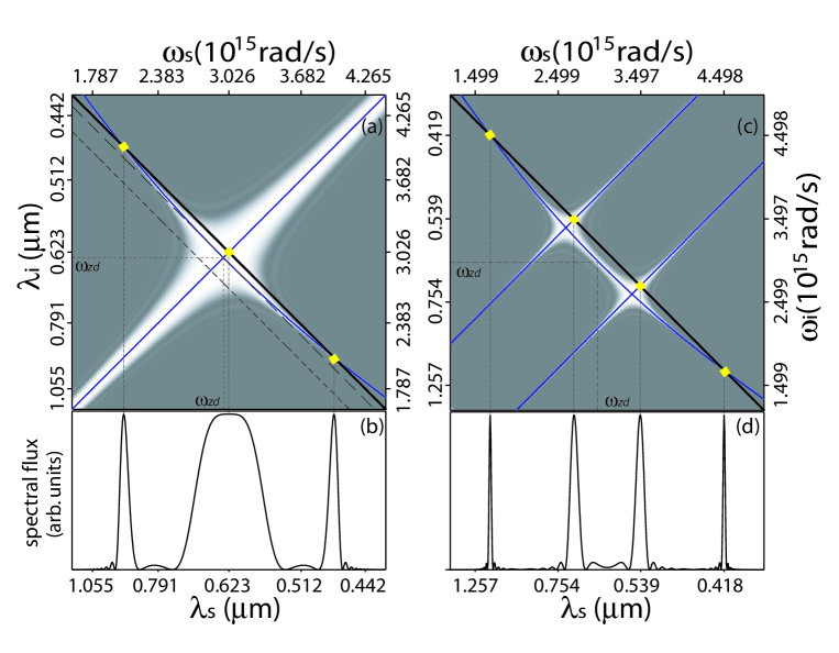
Here we concentrate on the second, non-trivial solution. To this end, it is instructive to consider a representation of the joint spectrum (see Eq.(II.1)) in (or ) space. In Fig. 1, we present such a plot for a particular fiber (see figure caption), where we have not, in contrast with the preceding analysis, resorted to a truncated Taylor series description. Here, the energy conservation delta function is represented by a straight line with negative unit slope, the trivial branch corresponds to a line with unit slope and the non-trivial branch is represented by a curve which near is elliptical. The spectral width of each of the two phase matching branches is inversely proportional to the fiber length (for graphical clarity in our plots we have assumed a short fiber). We have also overlapped a plot of the contour defined by , shown by the thin blue line, which corresponds to frequency pairs which yield perfect phase matching. Photon pairs are generated in areas of space where any of the two phase matching branches meet the energy conservation locus.
Fig. 1(a) shows an example of the joint spectral intensity for degenerate pumps, obeying (for which the energy conservation delta function is presented by the thick black, solid line), leading to a singles spectrum given by Eq. 8 with three peaks as shown in Fig. 1(b); while the outer peaks correspond to the nontrivial branch, the central peak corresponds to the trivial branch which is centered at the pump frequency. Note that if the degenerate pump frequency is made equal to , the two non-trivial peaks merge into a single peak, which then overlaps with the trivial peak. The long-segment dashed line with negative unit slope, represents the resulting energy conservation locus, tangent to the phasematching curve at . If the degenerate pump frequency is tuned down further to values such that (short-segment dashed line) then the non-trivial branch becomes inaccessible, leaving only the trivial contribution. Note that if the concavity of the phasematching ellipse is reversed (see below), then spectrally-distinct trivial and non-trivial contributions are observed for instead.
An analysis of Eq.(II.3) reveals that the non-trivial phase matching branch, to fourth order in the phasemismatch, has an elliptical locus in space. Note that our Taylor series description is valid only in the vicinity of the zero group velocity dispersion frequency; for large enough detunings from this frequency, the phase matching locus will deviate from the elliptical shape. Note also that for the degenerate pump case, the non-trivial phase matching characteristics are independent of the pump field. In this case, the phase matching curve is tangent at the point given by and (i.e. ) to a line with negative unit slope. The curvature at this point is proportional to the ratio ; thus, if this ratio is positive the concavity is oriented towards negative values of , while if the ratio is negative, the concavity is oriented in the opposite direction.
II.4 Phase matching properties for non-degenerate pumps
Let us now restrict our attention to a SFWM process in the non-degenerate pumps regime, i.e. . For negligible self/cross phase modulation, an analysis of Eq.(II.1) shows the existence of three distinct phasematching branches, two of them trivial and one non-trivial. It is straightforward to verify by direct evaluation of Eq. (II.1) in the low pump power limit, that frequency pairs on the straight lines (where ) fulfil perfect phasematching. These are trivial phasematching branches; indeed, together with energy conservation, they can be shown to be centered at: i), and ii), . In order to describe the non-trivial branch, we initially restrict our attention to a small spectral vicinity around for which second and higher-order terms in Eq. II.1 can be neglected. In this case, from Eq. II.1 it may be shown that frequency pairs on the line fulfil perfect phasematching. The fourth order term in Eq. II.1 (as well as higher order terms not included in our analysis) has the effect of adding curvature to this non-trivial phasematching branch.
In order to illustrate this discussion, Fig. 1(c) shows a representation of the joint spectral intensity, for the same fiber as in Fig. 1(a), but now in the non-degenerate pumps regime (with m and m). Note that here we have not resorted to a truncated Taylor series description. The energy conservation delta function is represented by a thick black, straight line with negative unit slope, while the trivial branches are represented by two straight lines with unit slope. The non-trivial branch is the curved line. As in the degenerate pump case, the spectral width of each of the three phase matching branches is inversely proportional to the fiber length. We have also overlapped a plot of the contour defined by , shown by the thin blue line. Photon pairs are generated in areas of space where any of the three phase matching branches meet the energy conservation locus.
The joint spectral intensity, represented by Fig. 1(c), leads to a singles spectrum with four peaks as shown in Fig. 1(d). While the outer peaks correspond to the nontrivial branch, the two inner peaks correspond to the trivial branches. In the case of non-degenerate pumps, depending on the pump configuration, it is possible to observe: i)two non-trivial peaks spectrally distinct from two trivial peaks (as in Fig. 1(d)), ii)a single non-trivial peak spectrally distinct from two trivial peaks (if the energy conservation locus meets the non-trivial branch tangentially), and iii)two trivial peaks only (if the energy conservation locus does not meet the non-trivial branch).
II.5 Effect of self/cross phase modulation
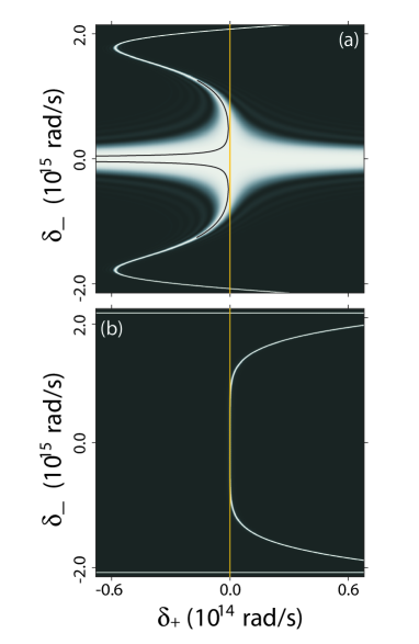
Let us now consider the effect of the self/cross-phase modulation term in the degenerate pumps regime (a similar behavior to that to be described here would be observed for the non-degenerate pumps regime), which becomes important for a sufficiently high pump peak power. For a given pump peak power, this term is an additive constant to the phasemismatch at zero power . Thus, a contour diagram in space formed by the contour for different power levels, represents a contour map of the function . Upon increasing the pump peak power, the phase matching contour shifts towards areas of space characterized by higher values of . As an illustration, Fig. 2(a) shows, for a given fiber (see figure caption), the effect on the phasematching contour of increasing the pump power. In the background, dark areas correspond to and light areas correspond to . It is clear that as the pump power level is increased, the phase matching contour shifts from the dark-light interface into the light areas. How much it shifts at a particular point on the curve depends on how slowly changes with frequency at that point. In general terms, for frequencies generated far from the pump frequency, e.g. on the non-trivial branch, this shift is much less pronounced than for frequencies generated near the pump frequency.
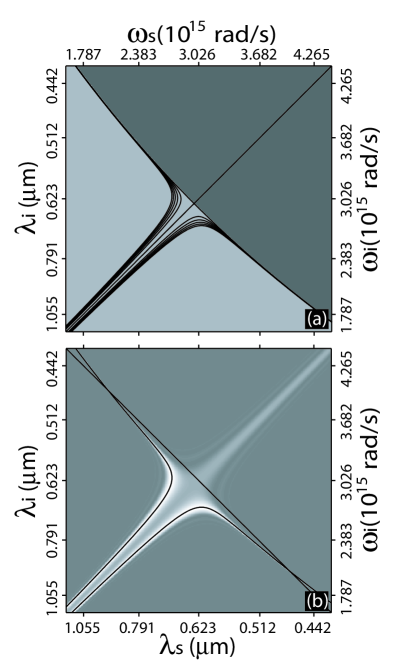
For the trivial phasematching branch and degenerate pumps, the self/cross phase modulation term leads to the suppression of perfect phasematching in areas of space where (indicated with dark shading in Fig. 2(a)). In contrast, in areas characterized by , the self/cross-phase modulation term splits the trivial branches into two parallel branches. In Fig. 2(b) we show a representation of the corresponding joint spectral intensity. The plot in shades of gray represents the phasematching function , which is maximized, with , for frequency pairs on the curved black lines; the straight black line represents the energy conservation locus. Note that while the dark-shaded area in Fig. 2(a) can be accessed with a pump in the normal dispersion () regime, the light-shaded area can be accessed with a pump in the anomalous dispersion () regime. The splitting of the trivial branch in the anomalous-dispersion regime is a manifestation of modulation instability. This phenomenon, which is equivalent to four-wave mixing phasematched by the self/cross-phase modulation, involves the appearance of two spectral sidebands, placed symmetrically around the pumpagrawal2007 . In the time domain, and in the stimulated regime, this leads to an ultrafast modulation with period (where is the spectral separation between the two sidebands).
III Conditions for the generation of ultra-broadband photon pairs
In this section, we derive conditions which guarantee the emission of highly broadband photon pairs by spontaneous four wave mixing utilizing narrowband pumps, in both the degenerate and non-degenerate pumps regimes. We will carry out the derivation of these conditions in the low pump power limit; in practice, these conditions are applicable for peak pump powers up to a few watts. From Eq.(II.1) it is clear that SFWM photon pair emission occurs at signal and idler frequency pairs which satisfy energy conservation, i.e. , and which in addition satisfy phasematching, i.e. . In order to obtain a large generation bandwidth, we must therefore engineer the phasematched region in the joint frequency space to maximize its overlap with the energy conservation locus, which is itself a straight line parallel to the axis. This translates into a condition on the orientation, curvature and location, of the phasematching contour .
Concretely, we expect broadband photon pair generation centered at signal and idler frequencies if four conditions are satisfied by these frequencies: i) they satisfy perfect phasematching, i.e. , ii) they obey energy conservation, i.e. the energy conservation locus contains this frequency pair, iii) the phasematching contour, which contains this frequency pair [as guaranteed by i)], is oriented parallel to the axis, and iv) the curvature of the phasematching contour vanishes at this frequency pair. Let us note that all degenerate frequency pairs (i.e. which are contained by the line ) fulfil the orientation requirement iii); indeed, from Eq. II.1 it may be shown that the phasematching contour fulfils (. We will therefore restrict attention to SFWM geometries centered at a degenerate frequency pair. Constrained by , the attainment of phasematching [condition i) above] is guaranteed if, in addition, as can be verified from Eq. II.1 (note that vanishes for ). Energy conservation [condition ii) above] can then be satisfied for if (see Eq.12), which in turn leads to two possible scenarios involving perfect phasematching at : i) degenerate pumps (DP) with (or ), and ii) non-degenerate pumps (NDP) with , where (or with ).
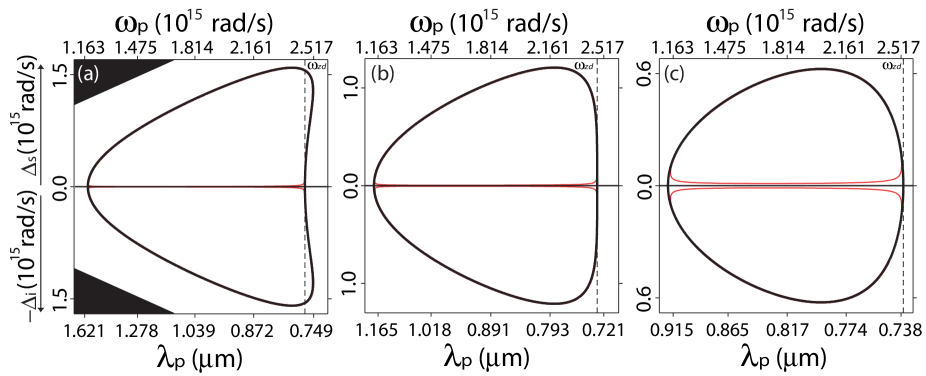
Conditions i) through iii) above can be fulfilled for any given fiber; they determine the pump and central generation frequencies which lead to the optimum SFWM bandwidth, for a specific fiber. The condition on the curvature [iv) above], on the other hand, helps us to select the fiber core radius, for a given air-filling fraction (or if our analysis were applied to standard step-index fiber, it helps to select the core radius for a given index contrast). In order to analyze the fulfilment of this condition, it is helpful to define , where ′ denotes a derivative with respect to evaluated at . This quantity represents the curvature of the phasematching contour at the origin of the generated frequencies space. It is possible to verify that the curvature associated with the non-trivial branch, in the low-power limit, is given by . Thus, the curvature is eliminated at radii for which ; in general, as will be discussed below, for each , one value of exists such that . The role of is illustrated in Fig. 3 for the degenerate pumps regime, where we present phasematching contours, represented by solid lines, in a generated frequencies (vertical axis) vs pump frequency (horizontal axis) diagram. Here, we express the generated frequencies as detunings from the pump frequency ; the top half of the diagram corresponds to the signal photon, while the bottom half corresponds to the idler photon. The three panels show the phasematching contour for a PCF with , for three different values of the core radius, for which: i) (with m) in panel (a), ii) (with m) in panel (b) and iii) (with m) in panel (c). Note that in all three cases, conditions i) through iii) from Sec. III are fulfilled. It is clear that in panel (b), the phasematching contour has an essentially vertical character [due to the fulfilment of condition iv)], indicating that even a narrow pump bandwidth is capable of generating remarkably broadband photon pairs.
Thus, for a source geometry which satisfies conditions i) through iv) above, the phasematching contour is a straight line around the zero dispersion point , which in addition coincides with the energy conservation locus. For frequency pairs sufficiently removed from , the phasematching contour will depart from a straight line due to terms with . Therefore, the attainable phasematching bandwidth is limited by the magnitude of these dispersion coefficients. Let us note that a fiber characterized by a lower air filling fraction involves a lower core-cladding dielectric contrast, and consequently the dispersive effects due to the waveguide contribution tend to be weakened. Such a weaker dispersion leads to reduced dispersion coefficients , which in turn limits the departure from a straight line of the phasematching contour. Therefore, lower values of permit greater SFWM bandwidths.
The process of SFWM leads to a remarkable symmetry between the two pumps configurations (DP and NDP) discussed above. Note that the two-photon state is determined by the phasemismatch function (see Eq. II.1); thus, if we can show that the DP and NDP scenarios lead to identical phasemismatch functions, this would imply that the two-photon states in these two scenarios are themselves identical. To this end, it is instructive to calculate the phasemismatch function difference between these two scenarios
| (14) |
As indicated in Eq. III, the phasemismatch function difference between the DP and NDP cases is equal to the NDP phasemismatch, for vanishing pump power and evaluated at , which is in turn equal to (see Eq. II.1). Thus, provided that perfect phasematching is achieved at degenerate signal and idler frequencies coinciding with , , and therefore the JSA functions, as given by Eq. II.1, for these two scenarios are in fact identical. Note that this symmetry is lost for sufficiently large pump bandwidths. Note, also, that this symmetry applies to the JSA, i.e. to the two-photon state, but not to the underlying phasematching function. In section V we discuss an interference effect, which arises due to identical outcomes obtained by two indistinguishable pathways, when pumping with DP and NDP pumps simultaneously.
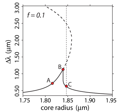
For a given fiber (characterized by the values for and ), the singles spectrum can be computed using Eq. 8, for a pump frequency such that conditions i) through iii) above are satisfied, in either the DP or NDP regimes. Given the symmetry discussed above, these two regimes give identical SFWM joint, as well as singles, spectra. Solid curves in Fig. 4(a) show the resulting optimum full width at half maximum singles bandwidth as a function of the core radius, where each curve is computed for a fixed value of the air-filling fraction. Here we have assumed a fiber length of cm, strictly monochromatic pumps and a vanishingly low pump peak power (we consider the effect of realistic pump power levels in the next section). Fig. 4(b) shows the zero dispersion frequency, which if conditions i) through iii) are satisfied corresponds to the central SFWM frequency, plotted vs the core radius for different values of the air filling fraction. These plots show that while spectra centered in the infrared tend to be broader than those centered in the visible, there is a considerable flexibility for choosing the central emission frequency while maintaining a large emission bandwidth (as compared to an approach based on PDC with crystals). The spectra from which the curves in Fig. 4(a) were calculated typically include a main emission mode involving an essentially flat spectrum and in some cases pairs of peaks around the main emission mode. For solid-line curves in Fig. 4(a), the valleys between satellite peaks and the main emission mode do not drop below of the maximum value. For certain radii, however, the spectrum exhibits pairs of well-defined satellite peaks around the main emission mode, resulting in voids in the spectrum. The bandwidth indicated in Fig. 4(a) by dashed-line curves is calculated from the outer-most slopes associated with these satellite peaks. It is important to point out that in the case of the NDP regime, these satellite peaks are in fact centered at the pump frequencies, and are due to trivial phasematching. Fig. 5 shows a curve similar to that in Fig. 4(a) for including the complete branch associated with satellite peaks. As can be seen, there are fiber core radii for which there are in fact more than one pair of satellite peaks. This is clear, for example, for the core radius labelled as C, for which there are two pairs of satellite peaks.
In Fig. 4(a), each solid-line curve is interrupted towards smaller radii, at the radius for which the zero dispersion frequency no longer exists [conditions i) through iii) assume the existence of a zero dispersion frequency]. It is apparent from the figure that the generation bandwidth tends to be larger for smaller air filling fractions. It is also apparent that for a given air-filling fraction, the attainable bandwidth exhibits a peak near the core radius for which the condition is fulfilled (shown as red dots). Note that the exact radius yielding the maximum bandwidth is slightly larger than . This is due to the influence of higher-order dispersive terms. In particular, it turns out that a small degree of curvature, with , can enhance the attainable bandwidth, if and have opposite signs. These parameters do in fact have opposite signs over a small range of radii larger than , explaining the shift of the peak from .
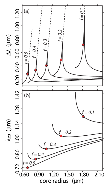
An interrupted dashed-line curve indicates that the emitted spectrum reaches the edge of the range of validity of the Sellmeier expansion used to compute dispersion for fused silica.
It is possible to re-interpret the phasematching contours in the low pump peak power limit, of Fig. 3, as non-degenerate pump frequencies in the vertical axis and degenerate signal and idler central frequencies in the horizontal axis. This is inverted with respect to the original interpretation, i.e. degenerate pumps in the horizontal axis and non-degenerate signal and idler in the vertical axis. The NDP pump frequencies which satisfy conditions i) through iii) above can now be determined by setting the degenerate signal and idler frequency at the zero dispersion frequency (denoted in the figure by a vertical dashed line), and reading out, on the vertical axis, the required NDP pump frequencies from the intersection of this vertical line with the phasematching contour. Thus, the example in Fig. 3(a) clearly shows the DP pump frequency coinciding with and also shows one set of NDP pump frequencies. Fig. 3(b) shows that source designs for which the phasematching contour curvature approaches zero (), which yields a large generation bandwidth in the DP regime, permit an infinite number of pump frequencies which can function as NDP pump frequencies (throughout the portion of the contour which is essentially vertical). This leads to the remarkable conclusion that an identical two-photon state is expected for any pair of pump frequencies amongst the possibly infinite set comprised of: i)the DP pump frequency, ii) possibly one or more discrete NDP frequency pairs, and iii) possibly a continuum of NDP pump frequency pairs.
A key consideration in the design of fiber-based two-photon sources is possible contamination from spontaneous Raman scattering, which occurs over a bandwidth of THz to the red from each pump spectral band. Our treatment in this paper does not take into consideration Raman gain; within the Raman bandwidth, a full analysis must take into consideration the combined effects of SFWM and spontaneous Raman scattering and therefore our theory is not completegolovchenko90 ; lin07 . However, since here we concentrate on broadband SFWM, where the generation bandwidth is much larger than the Raman bandwidth, our theory does adequately describe the overall two-photon state structure. The need for Raman suppression, in order to ensure high-quality signal-idler correlations, suggests a useful application for the symmetry between the DP and NDP regimes. For a configuration with an optimized SFWM bandwidth, we may pump at a pair of discrete NDP frequencies, which if sufficiently removed from the main emission mode, guarantees that this main emission mode is free from spontaneous Raman scattering.
Note that longitudinal fluctuations of the fiber properties may have an important effect on the properties of emitted light, particulary on the attainable bandwidthchen06 . In practice, this will set a fabrication tolerance on the amplitude and characteristic period of the fluctuations.
IV Ultra-broadband two-photon states: specific experimental designs
In this section we present specific designs of fiber-based, ultra-broadband photon-pair sources. As we have noted in the previous section, a small air-filling fraction tends to enhance the resulting SFWM generation bandwidth. Thus, for the specific examples to be considered here, we assume fibers with (which according to Ref. Wong2005 represents the lower bound for the range of validity of the step-index, effective-medium dispersion model which we have employed). We have selected three different source designs, involving radii labelled A, B and C in Fig. 5. For source A, the core radius is chosen so that the condition is fulfilled (corresponding to a vanishing phasematching contour curvature). For source B, the core radius is chosen so that we obtain the largest possible flat-spectrum generation bandwidth possible for (as discussed above, this maximum does not occur at the radius for which due to the effect of higher-order terms). For source C, we have selected the smallest core radius for which the two satellite peaks become well defined, i.e. such that the rate of emission reaches zero between the main emission band and the satellite peaks. In what follows we present emission spectra for these three cases. In all cases we will assume a fiber length of cm, a pump peak power of W, a nonlinear coefficient of , and a pump bandwidth of MHz, unless stated otherwise.
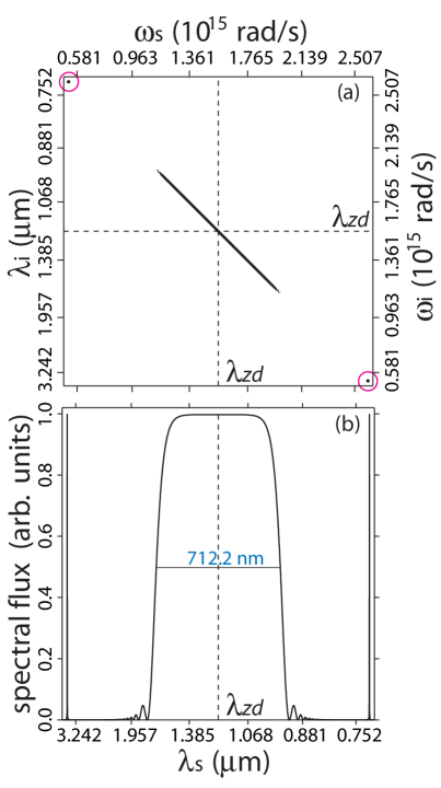
In Figs. 6 and 7 we present the two-photon state and singles spectrum obtained for an air-filling fraction and for a core radius of m (which corresponds to point A in Fig. 5). A number of choices for the pump frequencies which satisfy conditions i) through iii) above exist, and which therefore permit the largest possible generation bandwidth for the fiber in question: i)m in the DP regime, ii)m, m (one individual set of NDP frequencies), and iii) any pair of frequencies symmetrically displaced from within the range ; these constitute a continuum of NDP frequency pairs. It should be stressed that given the symmetry between the DP and NDP regimes, all of the above choices of pump frequencies will result in a two-photon state with the same joint spectrum .
In Fig. 6(a) we present a plot of the phasematching function , in space, for the DP regime. We have overlapped a plot of the perfect phasematching contour (for graphical clarity we have interrupted this contour towards the narrow, outer branches). Note that the trivial phasematching branch exhibits a power-induced splitting into two parallel branches. Fig. 6(b) shows the corresponding plot of the phasematching function in space, plotted for the NDP regime (where we have chosen pump frequencies corresponding to the discrete NDP frequency pair); specifically, we have chosen m and m. In both cases we have indicated with a yellow vertical line the energy conservation locus; ideally, for a large generation bandwidth the phasematching contour and the energy conservation locus should coincide. Remarkably, while the phasematching functions in the DP and NDP regimes are considerably different (as can be appreciated from the plots), the resulting two photon states are identical as demanded by the symmetry derived in the last section. Indeed, the portion of the phasematching function which coincides with the energy conservation locus may be seen to be identical in these two cases. Fig. 7(a) shows the joint spectral intensity , plotted as the contour corresponding to of the maximum value (note that the narrow diagonal width should be interpreted only schematically; the lines used are much thicker than the actual spectral width). As expected, from the symmetry discussed above, the joint spectral intensity is identical for the DP and NDP regimes. Note that in Fig. 7(a) there is a main emission mode centered at the zero dispersion frequency, and there are two satellite peaks, shown circled, involving highly non-degenerate frequency pairs.
The large degree of spectral entanglement evident in Fig. 7(a), could in principle be computed through the Schmidt number, . However, because of the very large ratio of the large to small diagonal widths, it is difficult for the sampling used to suffice in giving a reliable numerical estimate of . Our calculation gives us a lower bound (where indicates a factorable, or un-entangled, state).
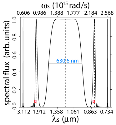
Fig. 7(b)shows the singles spectrum, calculated from Eq. 8 (and therefore assuming ideal monochromatic pumps), which once again is identical for the DP and NDP regimes. This spectrum exhibits a main emission mode centered at m, with a remarkably large FWHM bandwidth of nm. The singles spectrum also exhibits two satellite peaks centered at m and m, which in the NDP regime with two discrete peaks [scenario ii) above] are centered at the pump wavelengths. The emission bandwidth calculated from the outer slopes of these satellite peaks is nm. The fractional generation bandwidth for the main emission mode where is the FWHM bandwidth and is the central frequency gives a value of . This large generation bandwidth leads to a small correlation time, of fs, calculated as the width of the signal/idler emission time difference distribution.
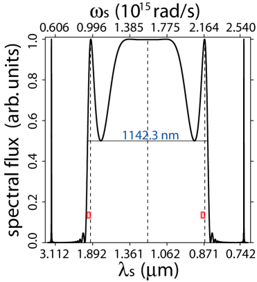
In Fig. 8 we present the singles spectrum obtained for an air filling fraction of and a core radius of m (corresponding to point B in Fig. 5, which yields the maximum possible flat-spectrum bandwidth for this air-filling fraction). As in the previous example, a number of choices for pump frequencies which satisfy conditions i) through iii) above exist. These include i) m in the DP regime, two discrete sets of NDP frequencies, at ii) m, m and iii) m, m, as well as iv) any pair of frequencies symmetrically displaced from within the range ; these constitute a continuum of NDP frequency pairs. Pump frequencies for scenarios i) and ii) are indicated in the figure by vertical dashed lines. Note that the slight departure from a flat central emission-mode is power-induced (an essentially flat spectrum would be recovered for a lower pump peak power). This source leads to a remarkably large generation bandwidth of nm, including a central mode and two adjacent satellite peaks; this corresponds to a fractional bandwidth of . Defining the bandwidth according to the outer slopes of the outer-most satellite peaks, the generation bandwidth becomes nm. Note that if non-degenerate pump frequencies are made to coincide with the first set of satellite peaks [scenario ii) above], then the main emission mode remains free from spontaneous Raman scattering; indeed the red rectangles in the figure indicate the THz spontaneous Raman scattering bandwidth. The large bandwidth of the main emission mode leads to a short correlation time of fs.
In Fig. 9 we present the singles spectrum obtained for an air filling fraction of and a core radius of m (corresponding to point C in Fig. 5), which represents the smallest core radius for which the two satellite peaks become well defined). As in the previous examples, a number of choices for pump frequencies which satisfy conditions i) through iii) above exist. These include i) m in the DP regime, two discrete sets of NDP frequencies, at ii) m, m and iii) m, m, as well as iv) any pair of frequencies symmetrically displaced from within the range ; these constitute a continuum of NDP frequency pairs. Pump frequencies for scenarios i) and ii) are indicated in the figure by vertical dashed lines. As in case B, the slight departure from a flat central emission-mode is power-induced, and would be eliminated in the low pump power limit. This source leads to a generation bandwidth of nm in the central emission mode, corresponding to a fractional bandwidth of and to a correlation time of fs. Defining the bandwidth according to the outer slopes of the inner-most satellite peaks, the generation bandwidth becomes nm. Likewise, defining the bandwidth according to the outer slopes of the outer-most satellite peaks, the generation bandwidth becomes nm.
V Quantum interference in spontaneous four-wave mixing
In section III we concluded that SFWM source designs exist where the pump frequencies may be chosen from a certain set, which may be finite or infinite, in such a way that any choice within this set yields an identical two-photon state. This set of pump frequencies is composed of all those which lead to the fulfilment of conditions i) through iii) of section III. It includes one DP frequency, coinciding with the zero dispersion frequency, and can also include individual pairs of NDP frequencies, as well as a continuum of NDP frequencies centered at the zero dispersion frequency. In this section we explore the effect of pumping simultaneously at the frequencies corresponding to two elements of this set, where coherence between the various frequencies involved is assumed to exist. In the discussion which follows, we assume that these two elements correspond to DP and NDP frequencies. Because a specific photon pair can then be created by any of two indistinguishable pathways, we expect an interference effect to occur when we vary the relative phase between these two sets of pump frequencies. This interference is such that the two individual pathways can interfere destructively leading to the suppression of photon pair emission, or they can interfere constructively. Variation of the relative phase between the two sets of pump frequencies, then leads to a sinusoidal modulation of the resulting rate of emission.
In order to analyze this interference effect, we assume a pump field including three narrow spectral bands (e.g. with a rectangular shape) centered at each of the DP and NDP frequencies. It is straightforward to verify that the total peak power available in each of the DP and NDP regimes should be identical, so that each pump configuration leads not only to the same joint spectrum, but also to the same rate of emission. One way of attaining this condition is if all pump spectral bands gave the same spectral width, where in addition the DP amplitude is higher than those for the NDP pumps. Specifically, we assume that the pump spectrum can be written as follows
| (15) |
where is the bandwidth (assumed to be small) for each of the pump spectral components, is the phase introduced between the two pump configurations and is unity for and zero otherwise. In the monochromatic limit where , each of the spectral bands may be represented by a delta function and the joint spectral amplitude may be computed analytically from Eq. II yielding
| (16) |
in terms of which represents the joint spectral amplitude for either the DP or NDP regimes [which are identical if conditions i) through iii) above are satisfied], and where represents a normalization constant. In Eq. 16 we have omitted a number of terms which are negligible, within the spectral range of interest, for a sufficient spectral separation between the DP and NDP spectral components. Note that the non-linear nature of the photon pair generation process implies that the period associated with the interference curve is . Note also that for a sufficient departure from monochromatic pumps in a realistic experimental situation, the joint spectral amplitude may be computed by numerical integration of Eq. II. We have found that for pump bandwidths up to nm, Eq. 16 may be used.
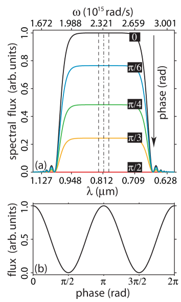
As an illustration, we will consider a specific example based on a photonic crystal fiber with core radius m and air filling fraction . This fiber has a zero dispersion frequency such that m. Conditions i) through iii) from section III are fulfilled for the DP pump frequency with m as well as for one NDP frequency pair with m and m. We have designed the source so that the three frequencies, which must be mutually coherent, could be taken from the broad spectrum of a femtosecond-duration pulse train, e.g. from a Ti:sapphire oscillator. Fig. 10(a) shows the singles spectrum, computed numerically from Eq. II assuming a pump spectral amplitude of the form shown in Eq. V, for a number of different phase values . Here we have assumed a peak pump power of W and likewise we have assumed that the three pump spectral bands have the same spectral width (equal to nm) and where the amplitude of the central one is higher by a factor of , compared to the other two. In Fig. 10(a), the DP and two NDP spectral components are indicated by vertical dashed lines. It is clear from the figure that as is increased from to , the height of the spectrum is reduced until emission is suppressed at . Fig. 10(b) shows the total emitted flux (given as the integrated spectral flux) as a function of . This plot explicitly shows the expected sinusoidal oscillations in the emitted flux.
VI Conclusions
We have analyzed the spectral properties of photon pairs generated by the process of spontaneous four wave mixing in single-mode fibers and for narrow-band pumps. Exploiting this analysis, we have derived conditions under which ultra-broadband photon pair generation with quasi-monochromatic pumps is possible. The resulting two-photon states are highly entangled as quantified by the Schmidt number and exhibit a particularly short correlation time. We have found that, for a given fiber, the attainable bandwidth is optimized if perfect phasematching is attained for signal and idler frequencies coinciding with the zero dispersion frequency. It is possible to design a photon pair source that satisfies this requirement which is based on degenerate, or on non-degenerate pumps. These two regimes, referred to as DP and NDP in the paper, lead to identical resulting two-photon states, revealing a remarkable symmetry in the process of SFWM. We have shown that this symmetry leads to a quantum interference effect when the fiber is pumped, for example, simultaneously by the pump frequencies corresponding to the DP and NDP regimes. This symmetry also permits, in the NDP regime, the generation of ultra-broadband photon pairs without contamination due to spontaneous Raman scattering; note that this represents a key concern in the design of fiber-based photon-pair sources. Although our theory can be applied to any fiber, we have focused our discussion on the use of photonic crystal fibers, described through a step index, effective medium dispersion model. We have shown that for a given air filling fraction in the cladding, the SFWM bandwidth is optimized for core radii close to that which leads to the fulfilment of the condition . Likewise, we have shown numerically that smaller air-filling fractions lead to greater SFWM bandwidths; this is due to a weakening of waveguide dispersion resulting from a lower nucleus-cladding index contrast. We have presented specific experimental designs, in some cases leading to over nm of emitted SFWM bandwidth. We expect that these results will be useful in the design of photon pair sources to be used in the exploration of high-dimensional continuous-variable entanglement.
Acknowledgements.
KGP acknowledges support from Ph.D. dissertation scholarship (207537) from CONACYT-Mexico. ABU acknowledges support from CONACYT-Mexico through grant 46370. RRR acknowledges CONACYT-Mexico for support through grant 46492.References
- (1) A. B. U’Ren, C. Silberhorn, K. Banaszek, I. A. Walmsley, R. Erdmann, W. P. Grice and M. G. Raymer, ” Laser Phys. 15, 146–161 (2005).
- (2) C. K. Law, I. A. Walmsley, and J. H. Eberly, Phys. Rev. Lett. 84, 5304 (2000).
- (3) L. Zhang, A. B. U’Ren, R. Erdmann, K. A. O’Donnell, C. Silberhorn, K. Banaszek and I. A. Walmsley, J. Mod. Opt. 54, 707–719 (2007).
- (4) I. Ali-Khan, C. J. Broadbent and J. C. Howell, Phys. Rev. Lett. 98, 060503 (2007).
- (5) B. Dayan, A. Peer, A. A. Friesem and Y. Silberberg, Phys. Rev. Lett. 93, 023005 (2004).
- (6) S. N. Molotkov, JETP Letters 68, 263 (1998).
- (7) D.C. Burnham and D.L. Weinberg, Phys. Rev. Lett. 25, 84 (1970).
- (8) L. J. Wang, C. K. Hong, and S. R. Friberg, J. Opt. B: Quantum and Semiclass. Opt. 3, 346 (2001); M. Fiorentino, P. L. Voss, J. E. Sharping and P. Kumar, IEEE Photon. Technol. Lett. 14, 983 985 (2002).
- (9) See for example: J. E. Sharping, J. Chen, X. Li, and P. Kumar, Opt. Express 12, 3086-3094 (2004); J. Fan, A. Dogariu, and L. J. Wang, Opt. Lett. 30, 1530 (2005); J. G. Rarity, J. Fulconis, J. Duligall, W. J. Wadsworth and P. S. J. Russell, Opt. Express 13, 534-544 (2005); J. Fan and A. Migdall, Opt. Express 13, 5777-5782 (2005); X. Li, P.L. Voss, J. E. Sharping, and P. Kumar, Phys. Rev. Lett. 94, 053601 (2005); J. Fulconis, O. Alibart, J. L. O Brien, W. J. Wadsworth, and J. G. Rarity, Phys. Rev. Lett. 99, 120501 (2007).
- (10) K. Garay-Palmett, H. J. McGuinness, O. Cohen, J. S. Lundeen, R. Rangel-Rojo, A. B. U’Ren, M. G. Raymer, C. J. McKinstrie, S. Radic, and I. A. Walmsley, Opt. Express 15, 14870-14886 (2007).
- (11) S.E. Harris, Phys. Rev. Lett. 98, 063602 (2007).
- (12) D. Strekalov, A. B. Matsko, A. Savchenkov, and L. Maleki, J. Mod. Opt. 52, 2233 (2005).
- (13) M. B. Nasr, B. E. A. Saleh, A. V. Sergienko, and M. C. Teich, Phys. Rev. Lett. 91, 083601 (2003).
- (14) M. B. Nasr, G. Di Giuseppe, B. E. A. Saleh, A, V. Sergienko, and M. C. Teich, Opt. Comm. 246, 521 (2005).
- (15) S. Carrasco, M. B. Nasr, A. V. Sergienko, B. E. A. Saleh, M. C. Teich, J. P. Torres, and L. Torner, Opt. Lett. 31, 253 (2006).
- (16) M. B. Nasr, S. Carrasco, B.E.A. Saleh, A. V. Sergienko, M. C. Teich, J. P. Torres, L. Torner, D. S. Hum, and M. M. Fejer, Phys. Rev. Lett. 100, 183601 (2008).
- (17) M. Hendrych, X. Shi, A. Valencia, J. P. Torres, pre-print arxiv:0807.4063 (2008).
- (18) K. O’Donnell and A. B. U’Ren, Opt. Lett. 32, 817 (2007).
- (19) M. M. Fejer, G. A. Magel, D. H. Jundt, and R. L. Byer, IEEE Quantum Electron. 28, 2631 (1992).
- (20) see for example: M. E. Marhic, N. Kagi, T. K. Chiang, and L. G. Kazovsky, Opt. Lett. 21, 573-575 (1996); C. J. McKinstrie, S. Radic, and A. R. Chraplyvy, IEEE J. Sel. Top. Quantum Electron. 8, 538-547 (2002); S. Pitois and G. Millot, Opt. Commun. 226, 415-422 (2003); J. D. Harvey, R. Leonhardt, S. Coen, G. K. L. Wong, J. C. Knight, W. J. Wadsworth, and P. St. J. Russell, Opt. Lett. 28, 2225-2227 (2003); M. E. Marhic, K. K. Y. Wong and L. G. Kazovsky, IEEE J. Sel. Top. Quantum. Electron. 10, 1133-1141 (2004); M. Gao, C. Jiang, W. Hu, and J. Wang, Opt. Express 12, 5603-5613 (2004); A. Y. H. Chen, G. K. L. Wong, S. G. Murdoch, R. Leonhardt, J. D. Harvey, J. C. Knight, W. J. Wadsworth and P. S. J. Russell, Opt. Lett. 30, 762–764 (2005); J. M. Chavez Boggio, J. D. Marconi, S. R. Bickham, and H. L. Fragnito, Opt. Express 15, 5288-5309 (2007)
- (21) L. Mandel and E. Wolf, Optical Coherence and Quantum Optics (Cambridge University Press, 1995).
- (22) K. P. Hansen, Opt. Express 11, 1503–1509 (2003).
- (23) T. A. Birks, J. C. Knight and P. St. J. Russell. Opt. Lett. 22, 961 (1997).
- (24) G. K. L. Wong, A. Y. H. Chen, S. W. Ha, R. J. Kruhlak, S. G. Murdoch, R. Leonhardt, J. D. Harvey and N. Y. Joly, Opt. Express 13, 8662–8670 (2005).
- (25) G. P. Agrawal, Nonlinear Fiber Optics, 4th Ed. (Elsevier, 2007).
- (26) see for example: E. A. Golovchenko, P. V. Mamyshev, A. N. Pilipetskii, and E. M. Dianov, IEEE J. Quantum Electron. 26, 1815-1820 (1990); S. Trillo and S. Wabnitz, J. Opt. Soc. Am. B 9, 1061-1082 (1992); F. Vanholsbeeck, P. Emplit, and S. Coen, Opt. Lett. 28, 1960-1962 (2003); P. L. Voss and P. Kumar, J. Opt. B: Quantum and Semiclass. Opt. 6, 762 (2004); S. Wabnitz, J. Lightwave Tech. 24, 1732-1738 (2006); A. S. Y. Hsieh, S. G. Murdoch, S. Coen, R. Leonhardt and J. D. Harvey, Opt. Lett. 32, 521-523 (2007); A. S. Y. Hsieh, G. K. L. Wong, S. G. Murdoch, S. Coen, F. Vanholsbeeck, R. Leonhardt, and J. D. Harvey, Opt. Express 15, 8104-8114 (2007).
- (27) Q. Lin, F. Yaman, and G.P. Agrawal, Phys. Rev. A 75, 023803 (2007)
- (28) J. S. Y. Chen, S. G. Murdoch, R. Leonhardt, and J. D. Harvey, Opt. Express 14, 9491-9501 (2006)