Tailored photon pair preparation relying on full group velocity matching in fibre-based spontaneous four wave mixing
Abstract
We study photon pair generation through scalar spontaneous four-wave
mixing in single-mode fibre and for frequency-degenerate pumps; we
concentrate on source geometries which fulfil full group velocity
matching (GVM), i.e. where the pump, signal and idler
propagate at identical group velocities. We discuss two
experimental techniques which permit the attainment of full GVM, and
discuss the resulting two-photon state properties. In particular, we
show that full GVM can lead to sources which approach phasematching
unconstrained by dispersion and therefore with a remarkably large
bandwidth. We also discuss the generation of nearly-factorable
states as an application of full GVM.
Keywords: spontaneous four wave mixing; entanglement; dispersion management
1 Introduction
The process of spontaneous four wave mixing (SFWM) in optical fibre, in which two pump photons are jointly annihilated to generate a signal and idler photon pair, leads to a remarkably versatile photon pair source[1, 2, 3]. Indeed, careful choice of the properties of the pump fields, which can be spectrally degenerate or non-degenerate, and of the properties of the fibre, can lead to two-photon states with widely disparate characteristics, ranging from factorable to highly entangled. Let us note that for a photon-pair source where the generation process is constrained to a single transverse mode, as in single-mode optical fibre, the resulting photon pairs are unentangled in transverse wavevector, leaving frequency as the only continuous-variable degree of freedom where entanglement may reside. While spectrally factorable two-photon states are essential for heralding of pure single photons[4], at the opposite extreme highly entangled photon pairs[5, 6] have useful applications in quantum-enhanced two-photon absorption[7], single-photon wavepacket teleportation[8], and quantum optical coherence tomography[9], among others. It has been shown that both factorable[10, 11] and highly entangled[5, 6] photon pairs may be generated through parametric downconversion (PDC) in second-order non linear crystals. However, SFWM greatly facilitates (with respect to PDC) the fulfilment of the conditions required for spectrally engineered states including both factorable and highly entangled ones. Furthermore, the guided nature of a spontaneous non-linear process in fibre leads to a higher parametric gains and evidently suppresses losses due to fibre-coupling. Thus, for example, as shown in Ref.[12], any fibre with two zero dispersion frequencies permits the generation of two-photon states with an arbitrary orientation in the joint frequency space , including factorable states as a special case.
In this paper, we study SFWM sources in the degenerate pumps regime for which full group velocity matching is fulfilled, i.e. where the pump, signal and idler propagate at identical group velocities. We show that a source with these characteristics may approach phasematching unconstrained by dispersion, and therefore lead to a remarkably large phasematching bandwidth, both for the pump and the generated light. Likewise, we show that long fibres which fulfil a certain condition on the second-order dispersion coefficients, permit the generation of nearly factorable states, in a source geometry which is well suited for multiple-pair generation through a large parametric gain.
2 Theory
The quantum state of photon pairs produced by spontaneous, scalar four wave mixing in an optical fibre of length can be obtained following a standard perturbative approach. It is given by
| (1) |
Here, represents the generation efficiency and is the joint spectral amplitude function (JSA), which describes the spectral entanglement properties of the photon pairs. For frequency-degenerate pumps, can be expressed as[12]
| (2) |
The JSA function is given in terms of the phase mismatch function , which includes a self/cross-phase modulation contribution for the pump with peak power , characterized by the nonlinear parameter , and the spectral shape of the pump.
It can be shown that in the case where the pumps are narrowband, it becomes possible to obtain an analytic expression in closed form for the JSA
| (3) |
in terms of a normalization constant and the monochromatic pump phasemismatch
| (4) |
For broadband, degenerate pumps it is likewise possible to obtain an expression for the JSA in closed analytic form, if we approximate the phasemismatch by a truncated power series in , and model the pump to have a Gaussian spectral envelope, i.e. (with central frequency and bandwidth ). Keeping up to second-order terms in the power series, it can be shown that the JSA may be expressed as , where we have defined frequency detunings , with and where represent central phasematched frequencies. Here, represents a normalization constant, and with
| (5) |
where denotes the error function, , and
| (6) |
in terms of the phasemismatch product evaluated within our second-order approximation, ,
| (7) |
In the previous equations we have introduced the definitions , with , and , in terms of the th order derivatives .
We are particularly interested in cases where the three fields (pump, signal and idler) propagate along the fibre with identical group velocities, which we refer to as full group velocity matching. In this case, the terms in Eq.(7) vanish. Assuming that phasematching is fulfilled at frequencies and , the term (see Eq.(7)) also vanishes. In this case, the two-photon state properties are fully determined to lowest order by group velocity dispersion terms. Let us note that for frequencies sufficiently removed from and , Eqns.(5) and (6) are no longer valid. This description is likewise not valid if , or if all second order dispersion coefficients vanish.
3 Phasematching properties of optical fibres with more than one zero dispersion frequency
In this paper we consider the use of step-index fibres (SIF), in both, the low and high dielectric contrast regimes, depending on the application. We are particularly interested in SFWM sources based on fibres which exhibit two zero dispersion frequencies (ZDF) in the spectral range of interest. Note that while some of the geometries to be considered exhibit a third ZDF, if this third ZDF is sufficiently removed from the two ZDFs under consideration, its effects are limited. As was shown in Ref.[12], fibres with two ZDFs permit a remarkable flexibility in terms of engineering the spectral entanglement properties of the resulting two-photon states. One way to represent the phasematching (PM) properties of a given fibre is to plot on a generated frequencies vs pump frequencies diagram, pairs of frequencies which yield perfect PM, i.e. . Such a plot is presented in Fig. 1(A) by the thick black contour, for a SIF with a fused silica cladding and a core such that the index contrast is (/ are the core/cladding indices of refraction), with a core radius of m. In this diagram, the horizontal axis corresponds to the pump frequency, and the vertical axis corresponds to the generated frequencies, expressed as a detuning from the pump frequency, i.e. (the top/bottom half of the diagram corresponds to the signal/idler photon). It can be seen from this illustration that parametric generation occurs for a range of pump frequencies essentially corresponding to the interval between the two ZDFs; for the specific case shown, the zero dispersion wavelengths are nm, and nm (this fibre has a third zero dispersion wavelength nm). The ZDFs are marked on the diagram by two blue vertical long-dashed lines; Fig. 1(B) shows that these frequencies correspond to the two points with vanishing slope on a vs plot (and therefore with ). Fig. 1(B) illustrates an important property of fibres with two ZDFs: within the frequency interval bounded by the two ZDFs, anomalous group velocity dispersion is observed, which is intimately connected with the appearance of closed-loop PM contours, as in Fig. 1(A). Note that for a finite pump power, self/cross phase modulation suppresses phase matching for degenerate signal/idler frequencies. As a consequence, modulation instability splits the trivial solution into two closely-spaced branches, where the separation increases with pump power[13]; here we have assumed and .
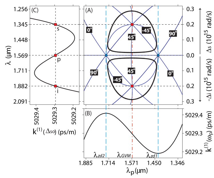
The two-photon spectral characteristics are governed to first order by the coefficients and . It was shown in Ref. [12] that, for a broadband pump, specific conditions on these parameters, which quantify the group velocity mismatch between the pump pulse and the generated photons, permit the generation of two photon states with useful properties including the important class of factorable states. It is instructive to plot in the space of Fig. 1(A) the GVM contours defined by the conditions , equivalent to (GVM between the pump and the signal photon), and , equivalent to (GVM between the pump and the idler photon). In Fig. 1(A) these contours correspond to the thin blue lines and are labelled by , which was shown in Ref. [12] to correspond to the orientation angle of the phasematched region in the joint frequency space ; the two GVM scenarios above lead to values and , respectively. In the figure we have in addition included the contours corresponding to . Pairs of values for which the GVM contours for all intersect, to be referred to as FGVM points, indicate values for which full group velocity matching is attained, i.e. . In general, there are four such points; two of these are and , indicated with blue circle markers in Fig. 1(A), (i.e. identical pump, signal and idler frequencies, with either or ). These two points are not phasematched, except in the limit of zero pump power. The other two FGVM points are within each of the two PM loops, as illustrated with red square markers in Fig. 1(A), and are therefore typically not phasematched. We will refer to the pump frequency at which this second set of FGVM points occur as ; in Fig. 1(A) this frequency is marked by the red dash-dot line. It is shown in Fig. 1(C), which shows a plot of vs , that the signal and idler frequencies corresponding to indeed lead to . In what follows, we study methods for achieving phasematched full GVM, and discuss the result of this on the two-photon state.
Let us concentrate on the two FGVM points at (see Fig. 1). For most source geometries, these points are not phasematched, since they occur within the PM loops. Here, we will explore two methods which lead to phasematching at these points. As we will see, in a realistic source design these two methods are most effective when used in conjunction, though each one is in principle independently capable of yielding photon pairs characterized by full GVM. Two of the FGVM points are directly linked to the ZDFs, which as is well known exhibit a strong dependence on the fibre core radius. In fact, the location of all four FGVM points can be varied through changes in the fibre core radius. In general terms, if the waveguide contribution to the dispersion is sufficiently strong relative to the material contribution (i.e. if there is a strong nucleus-cladding dielectric contrast), then more than one ZDF may exist, two of which may approach each other for certain core radii. This behavior is illustrated in Fig. 2(A), which shows for a SIF with a fused silica cladding and a core such that the index contrast is (/ are the core/cladding indices of refraction), plotted as a function of for different core radii . For mm, three ZDFs exist, where the two higher ones become degenerate at m. For the core radius at which the two higher ZDFs merge, the resulting degenerate ZDF fulfils . Also, in this case the four FGVM points merge into a single point. Note that a further reduction of the core radius leads to the suppression of PM. A fibre with two degenerate ZDFs at , pumped at , leads to the generation of photon pairs characterized by full GVM, centered also at .
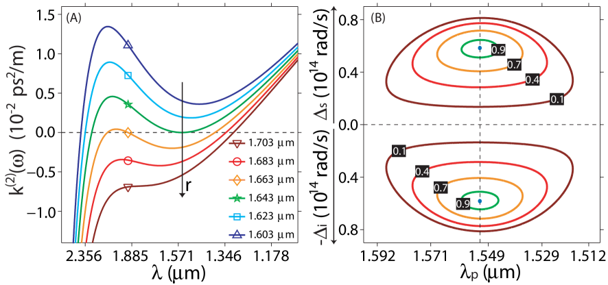
Alternatively, it is possible to exploit the self/cross phase modulation contribution to achieve PM at the two FGVM points. As has already been mentioned, the shape of the PM loops exhibits a dependence on the pump power . At small power levels, this effect manifests itself as the appearance of symmetric sidebands, detuned by from the pump frequency[13]; in contrast, the effect on the outer portions of the PM loops tends to be comparatively weaker. For example, in Fig. 1(A), the effect of self/cross phase modulation is only apparent in the inner loop. Thus, for small power levels, the PM loop splits into two separate loops. However, for sufficiently large pump power levels, the entire PM loops, including the outer areas, shrink. At a specific power level, the two PM loops become each a single point, which in fact corresponds to each of the two FGVM points. Note that increasing the power further beyond this value suppresses PM. This is illustrated in Fig. 2(B), where we show for a fibre with index contrast , and core radius m the PM loops resulting for five different pump power levels (W, W, W, W, W). Power level corresponds to that for which the PM loops become point-like. Thus, a pump centered at with the specific pump power leading to point-like PM loops, produces photon pairs characterized by full GVM.
What are the properties of photon pairs characterized by full GVM? On the one hand, as is clear from the discussion above, PM is achieved at individual points (in space). On the other hand, because the normally-dominant first order terms in the phasemismatch (see Eq.(7)) are suppressed, grows only weakly, as governed by second order terms, away from the points where perfect PM is achieved (and which correspond to FGVM points). This can translate into a large area in generated vs pump frequencies space where essentially perfect phasematching is attained. Thus, for a given pump frequency, broadband SFWM is generated, and in addition the pump frequency may be varied over a large spectral interval maintaining broadband SFWM photon-pair generation. Fig. 3 illustrates this behavior, for a fused-silica SIF of length cm with an index-contrast of . Fig. 3(A) shows a phasematching diagram, plotted in space, where for a monochromatic pump centered at (horizontal axis) we have computed the resulting singles spectrum . We have selected a fibre radius, m (as in Fig. 2(B)), for which (see Fig. 2(A)), the two ZDFs are nearly coincident, and for which the PM loops shrink down to the FGVM points through the self/cross phase modulation contribution. Thus, we have relied on a mixture of the two mechanisms above to obtain phasematched FGVM. On the one hand, the first mechanism discussed (based on choosing the core radius) leads to the merging of the four FGVM points, and a realistic pump power level suppresses PM. On the other hand, the second mechanism discussed (based on choosing the pump power level) tends to require large power levels to close down the loops. By making the loops small (for nearly coincident ZDFs), only a relatively small power level is required for the PM loops to become single points. This is the situation presented in Fig. 3(A), where we have assumed a pump power of W. The experimental implementation of these PM techniques necessitates an optical fibre with suitable dispersion properties. In the case of photonic crystal fibre and SIF with the appropriate core-cladding dielectric contrast, the required core radius can be reliably obtained through existing tapering techniques[14, 15, 16].
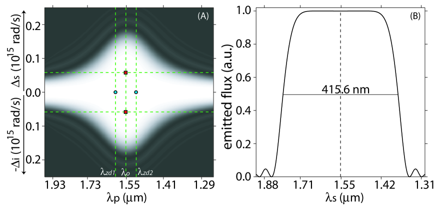
In Fig. 3(A) we have indicated the location of the four FGVM points. Perfect PM is achieved in the two FGVM points (red square markers in the figure). Note that the PM bandwidth is remarkably broad; the phasematched areas around these two points merge into a single, broad region, shown in white, characterized by nearly-perfect PM. Fig. 3(B) shows, for , (with nm) the resulting SFWM singles spectrum, with a full width at half maximum bandwidth of nm. An indication of the large pump bandwidth is that the pump wavelength may be varied between nm and nm, maintaining a generated SFWM bandwidth of . A possible application for a source with these characteristics, is a broadband parametric amplifier[17]. Indeed, with a phasematched region such as that shown in Fig. 3, the central frequencies for both the pump and the seed , to be amplified, could be chosen so that is anywhere within the white area. Such an amplifier would exhibit a constant level of noise within the phasematched area resulting from SFWM, i.e. without spectral structure. In addition, full GVM leads to the important property that the amplified seed does not develop additional spectral structure[18]. Note that in Ref.[19] we have presented an alternative recipe for ultrabroadand SFWM generation based on controlling higher-order dispersive terms. This technique (from Ref.[19]) permits an even wider generation bandwidth as compared to the technique presented here at the cost, however, of a greatly reduced pump bandwidth, i.e. for the technique from Ref.[19], the PM region in a diagram similar to Fig. 3(A) would be wider vertically, and much narrower horizontally.
4 Generation of nearly-factorable photon pairs
As has already been pointed out, for FWM sources exhibiting full GVM, while perfect PM occurs at isolated points (e.g. in space), increases only slowly away from these points. In the previous section we exploited this weak spectral dependence of to design a source which permits a remarkably broad generation bandwidth, over a wide range of pump frequencies. In this section, we exploit the fact that perfect PM occurs at isolated points to design relatively narrowband photon pair sources, where in addition by imposing a certain condition on the second order dispersion coefficients it becomes possible to approach factorability. For sufficiently narrowband photon pairs, the description in terms of Eqns.(5) and (6) becomes valid. Note that (see Eq.(6)) is independent of the fibre length ; the only dependence on is through parameter . The effect of increasing (which depends linearly on ) is to decrease the spectral width of the PM function. Thus, for sufficiently long fibres, the phasematched region in space becomes localized around the points which yield perfect PM. If the core radius and power level are chosen so that perfect PM occurs at the two FGVM points, then on the one hand and on the other hand . Under these conditions, from Eqns.(6) and (7) we can show that the phasematched regions become circular (i.e. the contours constant become circles) if the condition is satisfied.
If this condition is satisfied, then for a sufficiently broad pump bandwidth (so that the joint amplitude is determined solely by function ; see text before Eq.(5), the two photon state becomes factorable. The technique outlined here for the generation of factorable photon pairs presents some significant advantages over the techniques presented in Ref. [12]. Indeed, an important practical difference is that in the techniques presented earlier, it is essential to select a particular fibre length for a given pump bandwidth. Thus, increasing the fibre length, e.g. in order to increase the source brightness, would lead to the need for a simultaneous reduction of the pump bandwidth so as to maintain factorability. In the technique presented here, increasing the fibre length (while maintaining the pump bandwidth constant) has the effect of reducing the generation bandwidth, while maintaining factorability. The resulting decoupling of fibre length and pump bandwidth significantly enhances the experimental flexibility of this type of source. Furthermore, note that it becomes possible to obtain increasingly narrowband and high-flux nearly-factorable photon pair generation (in principle without limit) by increasing the fibre length. Indeed, we believe that this source could be well suited for experiments intended to generate multiple pairs simultaneously, through a large parametric gain[20].
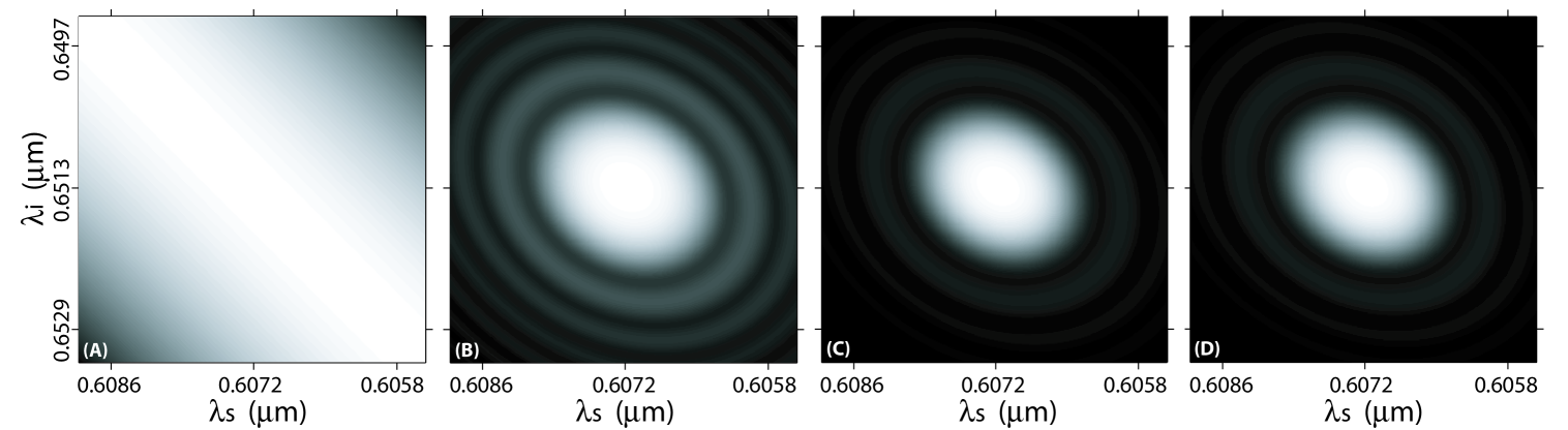
The fulfilment of condition is facilitated if exhibits a strong dependence on frequency. This translates into the need for relatively large higher-order dispersive terms, which is made possible by a fibre with a strong waveguide dispersion, i.e. with a strong nucleus-cladding dielectric contrast[21, 22, 23]. In Fig. 4 we illustrate the design of a nearly-factorable photon pair source based on these ideas. We have assumed a fibre composed of an air-guided bismuth borate glass rod with radius m; the combination of a particularly high-index glass and air guiding leads to a remarkably large dielectric contrast. The fibre radius is chosen so that the two ZDFs are in relative proximity, with nm and nm. The pump frequency must coincide with (with nm), while the FWHM pump bandwidth, nm, is large enough that the two-photon state is fully determined by the function . The fibre length, m, is chosen so as to restrict the emission bandwidth (to around nm FWHM). Finally, the pump power, W, is chosen so that the PM loops become point-like (at nm and nm) [see also Fig. 2(B)]; we have assumed a nonlinear coefficient of . Figure 4 shows, plotted as a function of the signal and idler frequencies: the pump envelope function in panel (A), the phasematching function in panel (B), the joint spectral intensity (JSI) in panel (C), and the JSI obtained through numerical integration of Eq.(2) in panel (D). It is evident from the figure that the agreement between the analytic and numerical calculations is excellent. Figs. 4(C) and (D) show that the resulting two-photon state is essentially factorable; the detection of an idler photon would herald a single photon in the signal mode with purity (where is the reduced density operator of the signal mode).
5 Conclusions
We have analyzed the spectral properties of two-photon states produced by spontaneous four wave mixing (SFWM) in a single mode optical fibre and in the degenerate-pumps regime, focusing our attention on fibres with more than one zero dispersion frequency (ZDF). We have explored the conditions under which we expect SFWM photon pair generation characterized by full group velocity matching (GVM), i.e. where the pump, signal and idler propagate at identical group velocities. We have presented two routes to phasematched full GVM, one based on engineering the fibre to have coincident ZDFs, and the other based on the self/cross phase modulation term; these two methods are most effectively used together. We have explored the consequences of full GVM, when satisfied together with phasematching (PM), on the two-photon spectral properties . We have shown that for a source with these characteristics, while perfect PM occurs at isolated pump and generated frequencies, because the phasemismatch grows only slowly from these points, we obtain a very large pump and signal/idler bandwidth over which essentially perfect PM is obeyed. Thus, it becomes possible to generate broadband SFWM photon pairs, for a large range of pump frequencies. Likewise, we have shown that, using long fibers which satisfy the condition on the second-order dispersion coefficients, we can exploit the fact that perfect PM occurs at isolated frequencies to obtain relatively narrowband, nearly-factorable two-photon states. We expect that these results will be useful for the practical implementation of fibre-based photon pair sources for quantum information processing applications.
Acknowledgement(s)
KGP, and RRR acknowledge support from CONACYT through project 46492; ABU acknowledges support from CONACYT through project 46370.
References
- [1] Fiorentino, M.; Voss, P. L.; Sharping, J. E.; Kumar, P. IEEE Photon. Technol. Lett. 2002 14, 983 -985.
- [2] Rarity, J. G.; Fulconis, J.; Duligall, J.; Wadsworth, W. J.; Russell, P. St. J. Opt. Express 2005 13, 534 -544.
- [3] Fan, J.; Migdall, A. Opt. Express 2005 13, 5777 -5782.
- [4] U’Ren, A. B.; Silberhorn, Ch.; Erdmann, R.; Banaszek, K.; Grice, W. P.; Walmsley, I. A.; Raymer, M. G. Las. Phys 2005, 15, 146–161.
- [5] Zhang, L.; U’Ren, A. B.; Erdmann, R.; O’Donnell, K. A.; Silberhorn, Ch.; Banaszek, K.; Walmsley, I. A. J. Mod. Opt. 2007 54, 707–719.
- [6] O’Donnell, K. A.; U’Ren, A. B. Opt. Lett. 2007 32, 817–819.
- [7] Dayan, B.; Pe’er, A.; Friesem, A. A.; Silberberg, Y. Phys. Rev. Lett. 2004 93, 023005.
- [8] Molotkov, S. N. JETP Lett. 1998 68, 263–270.
- [9] Nasr, M. B.; Saleh, B. E. A.; Sergienko, A. V.; Teich, M. C. et al. Phys. Rev. Lett. 2003 91, 083601.
- [10] Grice, W. P.; U’Ren, A. B.; Walmsley, I. A. Phys. Rev. A 2001 64, 063815.
- [11] Mosley, P. J.; Lundeen, J. S.; Smith, B. J.; Wasylczyk, P.; U’Ren, A. B.; Silberhorn, Ch.; Walmsley, I. A. Phys. Rev. Lett. 2008, 100, 133601.
- [12] Garay-Palmett, K.; McGuinness, H. J.; Cohen, O.; Lundeen, J. S.; Rangel-Rojo, R.; U’Ren, A. B.; Raymer, M. G.; McKinstrie, C. J.; Radic, S.; Walmsley, I. A. Opt. Express 2007, 15, 14870–14886.
- [13] Agrawal, G. P. Nonlinear Fiber Optics 4th Ed.; Elsevier:2007.
- [14] Wadsworth, W. J.; Ortigosa-Blanch, A.; Knight, J. C.; Birks, T. A.; Man, T. -P. M.; Russell, P. S. J. J. Opt. Soc. Am. B 2002, 19, 2148–2155.
- [15] Brambilla, G.; Koizumi, F.; Feng, X.; Richardson, D. J. Electron. Lett. 2005, 41, 400-402.
- [16] Foster, M. A.; Turner, A. C.; Lipson, M.; Gaeta, A. L. Opt. Express 2008, 16, 1300–1320.
- [17] Radic, S.; McKinstrie, C. J.; Jopson, R. M.; Centanni, J. C.; Lin, Q.; Agrawal, G. P. Electron. Lett. 2003, 39, 838–839.
- [18] Brainis, E.; Amans, D.; Massar, S. Phys. Rev. A 2005, 71, 023808.
- [19] Garay-Palmett, K.; U’Ren, A. B.; Rangel-Rojo, R.; Evans, R.; Camacho-López, S. To appear in Phys. Rev. A.
- [20] Rohde, P. P.; Mauerer, W.; Silberhorn, Ch. New J. Phys 2007, 9, 91.
- [21] Tong, L.; Hu, L.; Zhang, J.; Qiu, J.; Yang, Q.; Lou, J.; Shen, Y.; He, J.; Ye, Z. Opt. Express 2006, 14, 82–87.
- [22] Ebendorff-Heidepriem, H.; Petropoulos, P.; Asimakis, S.; Finazzi, V.; Moore, R.; Frampton, K.; Koizumi, F.; Richardson, D.; Monro, T. Opt. Express 2004, 12, 5082–5087.
- [23] Gopinath, J.; Shen, H.; Sotobayashi, H.; Ippen, E.; Hasegawa, T.; Nagashima, T.; Sugimoto, N. Opt. Express. 2004, 12, 5697-5702.