Extended Commissioning and Calibration of the Dual-Beam Imaging Polarimeter
Abstract
In our previous paper (Masiero et al. 2007) we presented the design and initial calibrations of the Dual-Beam Imaging Polarimeter (DBIP), a new optical instrument for the University of Hawaii’s m telescope on the summit of Mauna Kea, Hawaii. In this followup work we discuss our full-Stokes mode commissioning including crosstalk determination and our typical observing methodology.
Institute for Astronomy, University of Hawaii, 2680 Woodlawn Dr, Honolulu, HI 96822, masiero, hodapp, dmh, lin@ifa.hawaii.edu
1. Introduction
To study the linear polarization of asteroids and other point source objects, the Dual-Beam Imaging Polarimeter (DBIP) was commissioned in March of 2007 (Masiero et al. 2007). In August of 2007 we expanded DBIP’s capabilities to include analysis of circular polarization with the addition of a quarterwave plate. Typically, the most important quantities for analysis are the fractional polarizations , , and , expressed as percentages, and in the following text we will deal with these quantities when we refer to polarization measurements. Here we present our subsequent calibration and determination of systematic errors which were found to be comparable to statistical errors for typical observing situations: polarization.
2. Optical Setup
The original setup of DBIP was a serial arrangement of a halfwave plate in an encoded rotation stage, a filter and a double-calcite Savart plate placed between the telescope and the Tektronix CCD camera. To extend DBIP to full-Stokes sensitivity, a quarterwave plate in a rotation stage was placed ahead of the halfwave plate. This setup allows for simultaneous measurement of linear and circular polarization, though at the potential cost of increased crosstalk between polarizations, which is discussed further in §3.3. Figure 1, modified from Masiero et al. (2007), shows a schematic representation of the new optical path with the quarterwave plate added.

3. Calibration
As with any optical system, misalignments and imperfections in the components will lead to errors in measurement. In the case of DBIP, the waveplates are the most sensitive components to these errors, as they are the only moving parts and require precisely determined angular zero-points. Errors in angular alignment of the waveplate or tilt with respect to the optical axis as well as chromatic retardance or fast-axis angle variations will show up in our system as variations in measured position angle of polarization, depolarization of the signal, or crosstalk between linear and circular polarization. To minimize and quantify these errors we performed an extensive calibration campaign.
3.1. Waveplate Alignment
Our first step of calibration was to determine the alignment of the waveplate zero-points using known standard stars. Having already aligned the halfwave plate against standards before the installation of the quarterwave plate (Masiero et al. 2007), we were able to re-observe one of the same polarization standards (NGC 2024-1) in full-Stokes mode to align the quarterwave zero-point while confirming that we could reproduce the linear polarization results for this target. The set of observations of NGC 2024-1, both before and after the addition of the quarterwave plate, are listed in Table 1, where a circular polarization value of “—” indicates a measurement taken before the installation of the quarterwave plate.
| Name | Obs Date | Lin Pollit | Lin Polobs | Circ Polobs | ||
| BD-12 5133 | 3/24/07 | — | ||||
| NGC 2024-1 | 3/24/07 | — | ||||
| NGC 2024-1 | 1/17/08 | |||||
| NGC 2024-1 | 3/12/08 | |||||
| BD-13 5073 | 5/14/08 | |||||
| BD-12 5133 | 5/14/08 | |||||
| BD-12 5133 | 6/11/08 | |||||
| VI Cyg 12 | 6/11/08 |
| Name | Obs Date | Lin Pollit | Lin Polobs | Circ Polobs | |
|---|---|---|---|---|---|
| HD 64299 | 03/23/07 | — | |||
| WD 1615-154 | 03/24/07 | — | — | ||
| WD 1615-154 | 03/12/08 | — | |||
| WD 1615-154 | 05/14/08 | — | |||
| WD 1615-154 | 06/11/08 | ||||
| BD+28d4211 | 08/29/07 | — | |||
| WD 2149+021 | 08/30/07 | — | |||
| G191B2B | 01/17/08 | — |
3.2. Instrumental Polarization
In order to test for instrumental polarization or depolarization, we have observed polarized and unpolarized standard stars over a month baseline. Tables 1 and 2 give our measured polarizations and position angles for polarized and unpolarized standard stars, respectively, as well as literature values for these objects from Fossati et al. (2007), Schmidt, Elston, & Lupie (1992) and the Keck/LRISp standards111http://www2.keck.hawaii.edu/inst/lris/polarimeter/polarimeter.html. Our measurements for both polarized and unpolarized standards agree within of the literature values, confirming that instrument systematics are less than a effect. The only exceptions to this are the observations of BD-13 5073 and WD 1615-154. BD-13 5073 clearly shows evidence of variation in the amplitude and direction of polarization from the literature values over only a few years, showing it cannot be depended upon as a polarized standard. Our observation of WD 1615-154 on 6/11/08 shows anomalously high polarization compared to literature values and our previous observations at the level. With the current data it is unclear if the polarization properties of the object have changed or if this measurement is just an outlier.
3.3. Crosstalk
Instrumental crosstalk between Stokes vectors is one of the more subtle errors that can affect polarization measurements and quantifying its magnitude is a critical step toward obtaining high precision polarimetry. Crosstalk between linear Stokes vectors ( to or to ) happens when the zero-point location of the halfwave retarder is offset from the defined direction, and is easily corrected by aligning the waveplate, as discussed above in §3.1. Crosstalk from circular to linear and back ( to or to ) can be caused by waveplate offsets or by variations in retardance of the wave-plates as a function of wavelength, position on the plate, etc.
To fully determine the instrumental crosstalk, light with a known polarization must be sent through the instrument and measured upon exiting. It is possible to do this by installing polarizers just in front of the instrument during observations (recent examples include Perrin, Graham,& Lloyd 2008; Snik et al. 2006, etc.), however due to limited observing time and space in the optical path this was not a feasible calibration method for DBIP. Instead, we performed lab bench calibrations to quantify instrumental crosstalk.
To measure to crosstalk we sent a collimated light source through a linear polarizer into DBIP and measured one of the two exiting beams with a precision photodiode. By stepping the angular position of the input linear polarizer, we were able to fully characterize this linear-to-circular crosstalk. To measure to crosstalk a fixed quarterwave plate was installed after the linear polarizer. By stepping the linear polarizer again, we were able to vary the input polarization from circular to linear and back and characterize this circular-to-linear crosstalk.
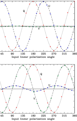
Figure 2 shows our measured polarization state for both setups as the input linear polarizer was stepped through degrees. Sinusoids describe the behavior of the polarization vectors in both setups and were fit with a chi-squared minimizer to the data to determine percentage crosstalk as well as any depolarization from the optics. We find that the circular polarization measured when inputing pure linearly polarized light had an amplitude of and an offset of , with crosstalk preferentially occurring when both Q and U are positive (around on our plot). We measure a depolarization of both linear signals varying from near to near . Since these crosstalk errors are only a few percent of the input signal, for sources with “typical” polarizations (i.e. ) the crosstalk error is comparable to the desired statistical errors of polarization, as we measured for our polarized and unpolarized standards.
For the measurement of circular-to-linear crosstalk, we find a small amount of linear polarization generated from a purely circularly polarized input beam, preferentially when is input. Note that the phased oscillation of and indicate a small misalignment of the quarterwave plate axes with the instrument-defined orientation, while it is the slight phase offset between and that is produced by the crosstalk. We also see clear evidence for a depolarization of the circularly polarized signal at the level of of the input polarization. For targets with total circular polarizations less than a few percent these errors should be comparable the noise error typically obtained in our observations.
4. Conclusion
We have presented the results of our extended commissioning of DBIP into full-Stokes mode. Crosstalk values are shown to be small and can be ignored for objects with “typical” (i.e. ) polarizations. With errors well constrained DBIP is now available for scientific studies of linear and circular polarization of point sources in the optical. DBIP has already been successfully used to characterize the polarization-phase curves of asteroids with some of the most pristine compositions in the inner solar system (Masiero & Cellino 2008) and a number of other programs to study small solar system bodies are currently under way.
Acknowledgments.
JM would like to thank Robert Jedicke and Colin Aspin for providing funding to attend the Astronomical Polarimetry 2008 conference. JM was partially funded under NASA PAST grant NNG06GI46G. The authors wish to recognize and acknowledge the very significant cultural role and reverence that the summit on Mauna Kea has always had within the indigenous Hawaiian community. We are most fortunate to have the opportunity to work with telescopes located on this sacred mountain.
References
- Fossati et al. (2007) Fossati, L., Bagnulo, S., Mason, E., Landi Del’Innocenti, E., 2007, ASP Conf., 364, 503
- Masiero & Cellino (2008) Masiero, J. & Cellino, A., 2008, Submitted to Icarus
- Masiero et al. (2007) Masiero, J., Hodapp, K.-W., Harrington, D. & Lin, H., 2007, PASP, 119, 1126
- Perrin, Graham,& Lloyd (2008) Perrin, M.D., Graham, J.R., & Lloyd, J.P., 2008, PASP, 120, 555
- Schmidt, Elston, & Lupie (1992) Schmidt, G.D., Elston, R., & Lupie, O.L., 1992, AJ, 104, 1563
- Snik et al. (2006) Snik, F., Bettonvil, F.C.M., Jagers, A.P.L., Hammerschlag, R.H., Rutten, R.J. & Keller, C.U., 2006, ASP Conf., 358, 205