Precision polarimetry with real-time mitigation of optical-window birefringence
Abstract
Optical-window birefringence is frequently a major obstacle in
experiments measuring changes in the polarization state of light
traversing a sample under investigation. It can contribute a signal
indistinguishable from that due to the sample and complicate the
analysis. Here, we explore a method to measure and compensate for the
birefringence of an optical window using the reflection from the last
optical surface before the sample. We demonstrate that this arrangement
can cancel out false signals due to the optical-window
birefringence-induced ellipticity drift to about 1%, for the values of
total ellipticity less than 0.25 rad.
(DOI: 10.1063/1.2835902)
I Introduction
Kerr effect, measured in liquid helium Sushkov et al. (2004) and liquid nitrogen Kanematsu and Zahn (1989), is a useful method for non-contact measurement and monitoring of the electric fields in low-temperature experiments. In particular, we have proposed to use this technique to monitor the electric field set-up in the new search for the neutron electric dipole moment ned . However, stress-induced birefringence of optical windows puts a limit on the sensitivity of this method. While constant stress due to the window mounting can be taken into account in modeling the signal by prior measurement of the optical-window birefringence Azzam and Bashara (1971); Stagg and Charalampopoulos (1993), or optically compensated in the experimental setup by use of retarder compensators Moog et al. (1989a, b); van Kuik-Van Meerten and Janeschitz-Kriegl (1962), for experiments requiring greater sensitivity, the time-dependent stress due to temperature drifts cannot be treated using the same methods, because the amount of retardation due to the optical window at a given moment is not known.
A careful experimental design, such as using low-stress window mounts and controlling the window temperature, can minimize this birefringence-induced polarization drift to as little as over the measurement time of 12 h McMillan et al. (2004). But this is still not good enough for more sensitive experiments, such as measurement of Kerr effect in liquid helium. In a practical experimental setup, we expect Kerr effect signals of the order of rad Sushkov et al. (2004). In our laboratory, where low-temperature optical access is implemented with a set of 1-in.-diameter, 2-mm-thick, epoxy-mounted fused-silica windows, testing with 632 nm light showed that window birefringence introduces offsets in polarization rotation and ellipticity, the latter being defined as inverse tangent of ratio of the axes of the polarization ellipse, on the order of 0.1 rad, which also depend on the window temperature. This offset drifts within a range of about rad over periods of hundreds of seconds, and this noise overwhelms the typical signal from the Kerr effect of liquid helium.
In past experiments, with the exception of those where the residual birefringence in instruments is small enough to be ignored Neto et al. (1991), various techniques have been used to distinguish the effects of the sample from those of the optical-window birefringence. In experiments with an isotropic sample, the incoming polarization of light can be rotated to distinguish the anisotropic feature of optical-window birefringence Jellison (1999). In other experiments, notably Kerr-effect experiments, modulation of the applied electric field is used to distinguish the signal from background noise Sushkov et al. (2004). Neither of these methods can be used in the application of Kerr effect for monitoring electric fields. Thus, we explore the feasibility of measuring and compensating for the optical-window birefringence drifts using the reflected light from the last optical surface before the sample.
II Experimental setup
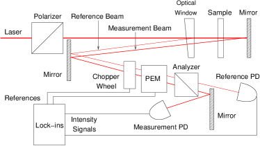
A typical experimental situation is simulated with two fused-silica parallelepipeds squeezed along the (approximately vertical) axis, making an approximate angle of with the azimuth of the incident light polarization. These are labeled as “optical window” and “sample” in the schematic diagram of our experimental setup shown in Fig. 1. In the absence of stress on the optical window, the maximum ellipticity that can be introduced by the sample on a single pass (depending on orientation) is equal to half of the birefringence-induced phase difference, given by, , where is the thickness of the sample, is the wavelength of the probe beam, and and are the indices of refraction along the slow and fast axes, respectively. We place a mirror just after the sample, so that the light double-passes the sample, and the entrance window is also the exit window. This arrangement works for measuring the Kerr effect since the effect of a small birefringence is additive for the double pass. The sample birefringence is what we want to measure, but this signal is obscured by the birefringence of the window. To mitigate this problem, we measure the window birefringence using the reflection from the back surface of the window.
The laser light at 632 nm with intensity of 1 mW is produced by a Hitachi laser diode HL6320G mounted on a Thorlabs TCLDM9 mount, with laser current and temperature controlled by Thorlabs LDC 201ULN and TED 200 controllers, respectively. The light is collimated to a beam width of about 1 mm diameter and is linearly polarized at rad from the optical axis of the sample by passing through a Glan-Thompson polarizer. The beam is reflected back by a near-normal-incidence dielectric mirror placed after the sample to pass through the optical-window and the sample twice. Then it goes through a fused-silica photoelastic modulator (PEM) operating at 50 kHz, whose optical axis is aligned vertically, and a Wollaston-prism analyzer, which makes an angle of rad with the optical axis of the PEM and, in this particular setup, is crossed with the Glan-Thompson polarizer. Additional dielectric mirrors were placed to ensure that all angles of reflection before the analyzer are less than 5∘ and to overcome space limitation for the modulation polarimeter. For angles of incidence up to 20∘, a commercial polarimeter, Thorlabs PAX5710VIS, was used to check that the dielectric mirrors used here do not alter the polarization state within the sensitivity of 1 mrad for ellipticity and 0.1 mrad for polarization rotation. For lock-in detection, and for calibration purposes, we introduce light modulation at 700 Hz with a chopper wheel. The measurement and the reference beams are calibrated separately (as explained below) using the synchronously detected signals from each photodiode. All data are collected with a LabVIEW program through the General Purpose Interface Bus (GPIB).
The main experimental limitation is posed by the fact that the window birefringence is nonuniform. This can impart different ellipticity to the measurement beam and the reference beam (Fig. 1). To minimize the effect of this nonuniformity, we superimpose the two beams as they pass through the window. In order to be able to separate the measurement and reference beams, as well as the reflection from the front surface of the window, a wedged window is used (a wedge angle of is sufficient in our setup). In our setup, we were able to reduce the distance between the two beams as they pass through the window to roughly one-tenth of the mm beam diameter.
The photodiode signal with the modulation polarimeter setup is given by,
| (1) |
where and are the polarization ellipticity and azimuth of the light incident on the PEM, is the intensity after the polarizer, before the window and the sample, and represents the reflection and absorption losses by the optical components before the photodiode. With if no additional rotation is introduced by the sample and the optical window, is the peak differential phase retardation introduced by the PEM, and is the PEM modulation frequency. The sine and cosine terms can be expanded in terms of Bessel functions of the first kind, multiplied by odd and even harmonics of , respectively. In the present experiment, we detect the dc signal and the first harmonic signal. These two signals are used for sensitive detection and calibration of Oakberg (1996).
| (2) |
Because the first-harmonic term depends only on and is completely insensitive to , this is a good polarimeter setup for measuring the light ellipticity. Furthermore, because 2.405 rad is a zero of the zeroth-order Bessel function of the first kind (), when the optical axis of the PEM forms the angle of rad with the analyzer, setting ensures that the dc offset is independent of incoming light-polarization Oakberg (1996). This fact can be used to check and calibrate the PEM modulation amplitude to 2.405 rad by, for example, placing a wave plate before the PEM and rotating it. PEM modulation amplitude is varied until the dc offset does not change with the rotation of the wave plate. In our setup, this method was used to calibrate the PEM retardation with approximately 1% accuracy, and the variation of PEM amplitude within the separation between the two beams as they traverse the PEM is within this accuracy. For this special value of , Eq. (2) simplifies to
| (3) |
The modulation polarimeter is thus calibrated for measuring ellipticity by dividing the intensity detected at the first harmonic of the PEM operating frequency, , by the dc offset. Thus, is given by
| (4) |
where , and and are the intensity at the first harmonic of PEM operating frequency, measured with a Signal Recovery 7265 lock-in amplifier, and the DC offset, measured at 700 Hz with a second Signal Recovery 7265 lock-in amplifier referenced to the chopper wheel, respectively. Before taking the ratio of two signals thus measured, we multiply the 50 kHz signal by an additional factor of 2 to account for reduction in intensity by 700 Hz chopping. Because the intensity signal itself contains the calibration information, this calibration can be done for both beams separately and, with additional lock-in amplifiers, simultaneously. Also, since and both depend linearly on , this calibration is independent of laser intensity fluctuations or reflection losses in optical components. For large values of ellipticity it was checked that this calibration method yields an agreement within 5% with Thorlabs PAX5710VIS, but the Thorlabs polarimeter cannot be reliably used to measure ellipticities smaller than 0.01 rad.
III Jones-matrix analysis
At nearly-normal incidence, up to leading order in the angle of reflection , reflection coefficients for light polarized parallel and perpendicular to the reflection plane are, respectively,
| (5) | ||||
| (6) |
This gives about reflection at each optical surface for typical optical-window materials, in the absense of inteference effects from highly parallel surfaces. Also, at a nearly-normal incidence, to first order in the angle of incidence, light is reflected without change in the polarization state.
For the experimental setup described above (Fig. 1), in the Jones-matrix formalism, the polarization states for the measurement beam () and the reference beam () are given by
| (7) | ||||
| (8) |
where, is the Jones vector for the initial polarization state, and , , , and are the Jones matrices modeling the birefringent optical-window, the sample, the dielectric mirror, and reflection at the last optical surface of the window, respectively. In our setup using a dielectric mirror, is equal to identity as it introduces negligible ellipticity and rotation. Likewise, at nearly-normal incidence, is equal to identity (except for changing overall light intensity) as well, since there is no measurable change in the polarization state upon reflection. And and are given as follows, up to a constant phase factor:
| (9) | ||||
| (10) |
where and are the birefringences of the sample and the window, respectively, is the angle between the fast axes of the birefringent window and the sample, and is the rotation matrix. We assume that the sample birefringence has a fixed alignment, since it is controlled by the experimental setup.
In the special case where the fast axis of the birefringent window is aligned with fast axis of the sample, the birefringences simply add. The general case with misaligned optical axes presents a more difficult problem for general values of and Savukov and Budker (2007). However, as long as and are small, for linearly polarized at rad to the fast axis of the sample, up to the terms linear in and , we obtain
| (11) | ||||
| (12) |
In terms of Jones vector components, the light ellipticity is given by Huard (1997)
| (13) |
where and are the complex upper and lower components of a Jones vector respectively. To first order in and , the ellipticities at the output are
| (14) | ||||
| (15) |
The optical-window term appearing in the measurement beam can be independently determined from the light reflected from the back surface of the window. Thus, to first order in and , we can subtract the ellipticities of the two beams,
| (16) |
In the preceding calculations, if we retain higher-order terms, assuming , the leading error term is for arbitrary orientation of optical-window birefringence. For example, in an experimental setup measuring sample birefringence on the order of rad, with the optical-window birefringence on the order of rad, this would lead to error of less than rad, or a fractional error less than 0.5% of the sample birefringence. In contrast, for the same experimental setup, but without the active cancellation of optical-window birefringence, the error would be on the order rad and would overwhelm the sample signal.
Additional considerations that may need to be taken into account are:
-
•
Rotation of polarization state of the reference beam introduced upon reflection at the back surface of the window: Since reflection coefficients as given in Eqs. (5) and (6) depend on the angle of reflection and indices of refraction, different fractions of incoming light are reflected for light polarization parallel and orthogonal to the fast axis of the medium, resulting in rotation. For an order of magnitude estimate of this rotation, let the fast axis of the medium be parallel to the plane of reflection. Let and for the light polarized along the fast axis, and for the slow axis, and let be average of and . In the limit where and , when the incident light is polarized at , the resulting rotation is,
(17) The quantity is related to the single-pass phase shift by:
(18) Since our modulation polarimeter setup is insensitive to rotation, we consider only the change in the ellipticity due to the rotation. Given a small rotation from , to the leading order in and , the change in the ellipticity of the reference beam traversing the window on the return trip after reflection is,
(19) When the typical values (, , , and rad) are plugged in, the fractional change of due to is several orders of magnitude less than unity.
-
•
Ellipticity introduced into the measurement beam by the mirror: In the case of a dielectric mirror, residual stress in each dielectric layer can introduce additional ellipticity. At room temperature, a separate measurement shows that the dielectric mirror used introduces ellipticity less than 1 mrad at incidences within .
-
•
Spatial nonuniformity in the birefringence of window: If the birefringence in the window is not uniform and the two beams pass through different parts of the window on the return trip, they may acquire different ellipticity, a systematic indistinguishable from a genuine signal. In our experiments this is the dominant source of error with 1%–2% change in birefringence per 1 mm.
IV Results
The empty polarimeter has noise of , but with either the window or the sample in place, the temperature-dependent drift in the birefringence dominates the error. Although in this experiment the ellipticity measurements of the two beams were separated in time by about half a minute, leading to imperfect cancellation, in principle, the drift in window birefringence can be canceled out with simultaneous monitoring of both beams.
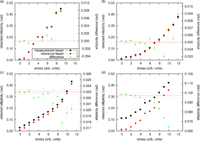
As a check of the experimental setup, a series of measurements was made without anything in the sample space. The window birefringence is varied by applying pressure on the fused-silica 1∘ optical wedge with a vise. In this case, we expect and , the ellipticities of measurement beam and the reference beam, respectively, to be equal. The obtained results (Fig. 2a) indicate that the cancellation of the window birefringence is, indeed, possible, and allow an estimate of the level to which such cancellation can be done. We obtain a result consistent with zero difference between the two signals, and the spread of the points indicates that we can cancel out the window birefringence to about of its value with the current setup, limited by the nonuniformity of window birefringence and the finite beam width.
For measurements with a sample, we take the sample birefringence to be the difference in ellipticity detected in the measurement beam when the sample is inserted and taken out at zero applied stress on the optical-window. This difference is measured at the beginning and end of each measurement, and the average is indicated by the dashed line. The two measurements also give an order-of-magnitude estimate of the uncertainty of the sample birefringence due to temperature-dependent drifts, indicated by dotted lines on the plots. For small total ellipticities, this estimate is comparable to the error of each data point obtained from the spread of points over a 10-s measurement period.
The results for the measurement beam and the reference beam as the stress on the optical-window is varied show a good agreement with the measured sample ellipticity, particularly for small values of and . At larger values of stress on the window, the nonuniformity of window birefringence dominates the difference and accurate measurement of the sample becomes more difficult. The nonuniformity of optical-window birefringence is measured to be about 1% change of total birefringence over the beam width of 1 mm for our setup.
At larger values of and , we see the second-order effects due to the rotation introduced by the birefringent window. In principle, these effects can be compensated for in the analysis numerically using Jones-matrix formalism, provided that the azimuth is measured in addition to the ellipticity. Since, as shown in Eq. (1), the even harmonics of are sensitive to , the rotation can be measured by using a lock-in amplifier to recover the second-harmonic amplitude.
V Conclusions
This work demonstrates that the birefringence of a window can be measured using the reflection from the last optical surface before the sample. This measurement can be done simultaneously with the measurement of the total birefringence of the optical-window and the sample, allowing for a real-time correction for window birefringence drifts during the experiment. This cancellation can effectively be done to the precision of of total ellipticity drift, limited by the spatial optical-window birefringence nonuniformity, for the values of optical-window birefringence less than 0.25 rad.
This work has been supported in part under Los Alamos National Laboratory Project 20040104DR, “Testing Time-Reversal Symmetry with Ultracold Neutrons and with Solid State Systems,” and by the National Science Foundation through grant #0554813.
References
- Sushkov et al. (2004) A. O. Sushkov, E. Williams, V. V. Yashchuk, D. Budker, and S. K. Lamoreaux, Phys. Rev. Lett. 93, 153003/1 (2004).
- Kanematsu and Zahn (1989) A. Kanematsu and M. Zahn, 1989 Annual Report. Conference on Electrical Insulation and Dielectric Phenomena (Cat. No.89CH2773-0). IEEE. pp. 429–34 (1989).
- (3) SNS Neutron EDM Experiment, http://p25ext.lanl.gov/edm/edm.html.
- Azzam and Bashara (1971) R. M. A. Azzam and N. M. Bashara, Journal of the Optical Society of America 61, 600 (1971).
- Stagg and Charalampopoulos (1993) B. J. Stagg and T. T. Charalampopoulos, Journal of Physics D (Applied Physics) 26, 2028 (1993).
- Moog et al. (1989a) E. R. Moog, C. Liu, S. D. Bader, and J. Zak, Phys. Rev. B 39, 6949 (1989a).
- Moog et al. (1989b) E. R. Moog, J. Zak, M. L. Huberman, and S. D. Bader, Phys. Rev. B 39, 9496 (1989b).
- van Kuik-Van Meerten and Janeschitz-Kriegl (1962) E. van Kuik-Van Meerten and H. Janeschitz-Kriegl, Journal of Scientific Instruments 39, 301 (1962).
- McMillan et al. (2004) T. McMillan, P. Taborek, and J. E. Rutledge, Review of Scientific Instruments 75, 5005 (2004).
- Neto et al. (1991) J. M. Neto, E. Munin, and A. B. Villaverde, Measurement Science and Technology 2, 1026 (1991).
- Jellison (1999) G. E. Jellison, Appl. Opt. 38, 4784 (1999).
- Oakberg (1996) T. C. Oakberg, SPIE-Int. Soc. Opt. Eng. Proceedings of the SPIE - The Internatinoal Society for Optical Engineering 2873, 17 (1996).
- Savukov and Budker (2007) I. Savukov and D. Budker, Appl. Opt. 46, 5129 (2007).
- Huard (1997) S. Huard, Polarization of Light (John Wiley & Sons, 1997), pg. 21.