The Kinetostatic Optimization of a Novel Prismatic Drive
Abstract
The design of a mechanical transmission taking into account the transmitted forces is reported in this paper. This transmission is based on Slide-o-Cam, a cam mechanism with multiple rollers mounted on a common translating follower. The design of Slide-o-Cam, a transmission intended to produce a sliding motion from a turning drive, or vice versa, was reported elsewhere. This transmission provides pure-rolling motion, thereby reducing the friction of rack-and-pinions and linear drives. The pressure angle is a suitable performance index for this transmission because it determines the amount of force transmitted to the load vs. that transmitted to the machine frame. To assess the transmission capability of the mechanism, the Hertz formula is introduced to calculate the stresses on the rollers and on the cams. The final transmission is intended to replace the current ball-screws in the Orthoglide, a three-DOF parallel robot for the production of translational motions, currently under development for machining applications at École Centrale de Nantes.
keywords:
Optimal design, Slide-o-Cam, Pressure angles, Hertz’s formula1 Introduction
In robotics and mechatronics applications, whereby motion is controlled using a piece of software, the conversion from rotational motion to translational one is usually realized by means of ball-screws or linear actuators. The both are gaining popularity. However they present some drawbacks. On the one hand, ball-screws comprise a high number of moving parts, their performance depending on the number of balls rolling in the shaft groove. Moreover, they have a low load-carrying capacity, due to the punctual contact between the balls and the groove. On the other hand, linear bearings are composed of roller-bearings to figure out the previous issue, but these devices rely on a form of direct-drive motor, which makes them expensive to produce and maintain.
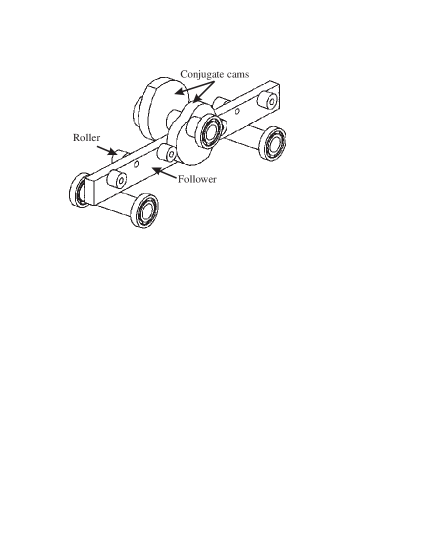
A novel transmission, called Slide-o-Cam is depicted in Fig. 1 and was introduced in [1] to transform a rotational motion to a translational one. Slide-o-Cam is composed of four main elements: () the frame; () the cam; () the follower; and () the rollers. The input axis on which the cams are mounted, named camshaft, is driven at a constant angular velocity by means of an actuator under computer-control. Power is transmitted to the output, the translating follower, which is the roller-carrying slider, by means of pure-rolling contact between the cams and the rollers. The roller comprises two components, the pin and the bearing. The bearing is mounted to one end of the pin, while the other end is press-fit into the roller-carrying slider. Consequently, the contact between the cams and rollers occurs at the outer surface of the bearing. The mechanism uses two conjugate cam-follower pairs, which alternately take over the motion transmission to ensure a positive action; the rollers are thus driven by the cams throughout a complete cycle. Therefore, the main advantages of cam-follower mechanisms with respect to the other transmissions, which transform rotation into translation are: () the lower friction; () the higher stiffness; and () the reduction of wear.
Many researchers have devoted their efforts to study contact stress distribution and predict surface fatigue life in machine parts under different types of loading. Indeed, when two bodies with curved surfaces, for example, a cam and a roller, are pressed together, the contact is not linear but a surface. The stress occurred may generate failures such as cracks, pits, or flaking in the material. Heinrich Rudolf Hertz (1857-1894) came up with a formula to evaluate the amount of surface deformation when two surfaces (spherical, cylindrical, or planar) are pressed each other under a certain force and within their limit of elasticity.
2 Synthesis of Planar Cam Mechanisms
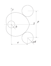
Let the - frame be fixed to the machine frame and the - frame be attached to the cam, as depicted in Fig. 3. is the origin of both frames, is the center of the roller, and is the contact point between the cam and the roller.
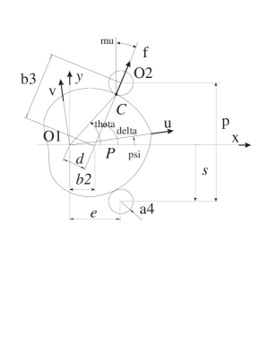
The geometric parameters are illustrated in the same figure. The notation used in this figure is based on the general notation introduced in [6], namely, () is the pitch, i.e., the distance between the center of two rollers on the same side of the follower; () is the distance between the axis of the cam and the line of centers of the rollers; () is the radius of the roller-bearing, i.e., the radius of the roller; () is the angle of rotation of the cam, the input of the mechanism; () is the position of the center of the roller, i.e, the displacement of the follower, which is the output of the mechanism; () is the pressure angle; and () f is the force transmitted from the cam to the roller.
The above parameters as well as the surface of contact on the cam, are determined by the geometric relations derived from the Aronhold-Kennedy Theorem [2]. As a matter of fact, when the cam makes a complete turn (), the displacement of the roller is equal to , the distance between two rollers on the same side of the roller-carrying slider (). Furthermore, if we consider that Fig. 3 illustrates the home configuration of the roller, the latter is below the -axis when . Therefore, and the input-output function is defined as follows:
| (1) |
The expressions of the first and second derivatives of are given by:
| (2) |
The cam profile is determined by the displacement of the contact point around the cam. The Cartesian coordinates of this point in the - frame take the form [6]
| (3a) | |||||
| (3b) | |||||
the expression of coefficients , and being
| (4a) | |||||
| (4b) | |||||
| (4c) | |||||
where is the directed angle between the axis of the cam and the translating direction of the follower. is positive in the counterclockwise (ccw) direction. Considering the orientation adopted for the input angle and the direction defined for the output , as depicted in Fig. 3,
| (5) |
The nondimensional design parameter is defined below and will be used extensively in what remains.
| (6) |
The expressions of , and can be simplified using Eqs. (1), (2), (4a–c), (5) and (6):
| (7a) | |||||
| (7b) | |||||
| (7c) | |||||
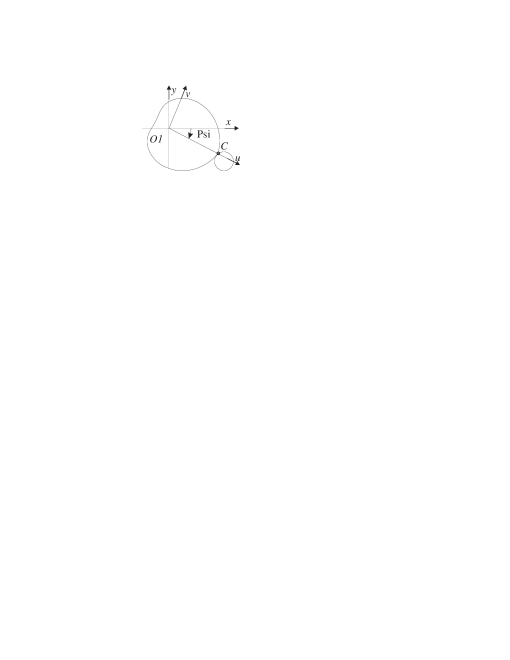
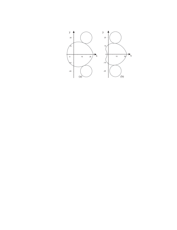
From Eq. (7), cannot be equal to . That is the first constraint on . An extended angle was introduced in [7] to know whether the cam profile can be closed or not. Angle is defined as a root of Eq. (3). In the case of Slide-o-Cam, is negative, as shown in Fig. 4. Consequently, the cam profile is closed if and only if .


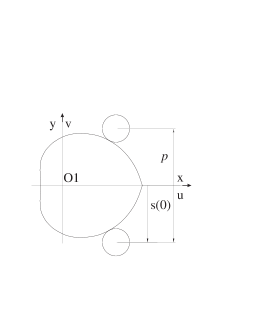
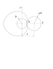
2.1 Pitch-Curve Determination
The pitch curve is the trajectory of , the center of the roller, distinct from the trajectory of the contact point , which produces the cam profile. are the Cartesian coordinates of point in the - frame, as depicted in Fig. 3. Hence, the Cartesian coordinates of the pitch-curve in the - frame are
| (8a) | |||||
| (8b) | |||||
2.2 Geometric Constraints on the Mechanism
In order to lead to a feasible mechanism, the radius of the roller must satisfy two conditions, as shown in Fig. 5a:
-
•
Two consecutive rollers on the same side of the roller-carrying slider can not collide. Since is the distance between the centers of two consecutive rollers, the constraint has to be respected.
-
•
Likewise, the radius of the camshaft has to be considered. Therefore, the following condition has to be respected: , which can written in terms of :
| (9) |
According to the initial configuration of the roller, as depicted in Fig. 3, the -component of the Cartesian coordinate of contact point is negative in this configuration, i.e., . Moreover, from the expression of and for parameters and given in Eqs. (3b), (7b & c), respectively, the above relation leads to the condition:
It turns out that the constraint leads to a constraint on , namely [5],
| (10) |
2.3 Curvature of the Cam Profile
The curvature of any planar parametric curve, in terms of the Cartesian coordinates and , and parameterized with any parameter , is given by [3]:
| (11) |
The curvature of the pitch curve is given in [5] as
| (12) |
provided that the denominator never vanishes for any value of , i.e., provided that
| (13) |
Let and be the radii of curvature of both the cam profile and the pitch curve, respectively, and the curvature of the cam profile. Since the curvature is the reciprocal of the radius of curvature, we have and . Furthermore, due to the definition of the pitch curve, it is apparent that
| (14) |
Writing Eq. (14) in terms of and , we obtain the curvature of the cam profile as
| (15) |
2.4 Physical constraints
Let us assume that the surfaces of contact are ideal, smooth and dry, with negligible friction. The relations between the forces of contact are described below:
-
-
Two relations follow from the strength of materials. Besides, the bearing shafts are subject to shearing, whereas the camshafts are subject to shearing and bending. Consequently, we come up with the following relations:
| (16) | |||||
| (17) |
where,
-
is the diameter of the camshaft ();
-
is the diameter of the bearing s shaft ();
-
is the torque applied to the camshaft;
-
is the maximum allowable stress inside the cam axis which cannot be exceeded in the camshaft;
-
is the maximum stress inside the bearing’s axis which cannot be exceeded in the bearing shaft;
Let us assume that the material of the cam and the one of the roller have the same Young modulus and Poisson ratio. The Hertz’s formula [8] yields the maximum pressure of contact between the cams and rollers. Depending on the material, surface roughness and possible surface treatment, the Hertz pressure must remain smaller than a maximum value .
| (18) |
where,
-
is the axial load, ,
-
is the equivalent radius of the contact,
-
is the width of the cam and the roller,
-
is the maximum pressure acceptable between two surfaces of contact.
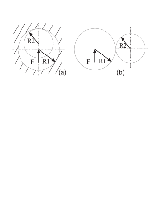
To minimize the Hertz pressure, we must maximize the equivalent radius of contact. Figure 6(a) shows an optimal configuration to minimize the Hertz pressure [4], i.e. the stresses bear opposite sign. The roller of radius is included in the roller of radius being smaller than but close to it. However, this layout does not occur in Slide-o-Cam because the contact changes between the cam and rollers. Indeed, Fig. 6(b) depicts the actual configuration. In this case, the only way to minimize the Hertz pressure is to maximize the diameter of the roller and the curvature of the cam.
The Hertz pressure is evaluated only when the cam pushes the roller. The active interval is [5]:
2.5 Implementation
A graphic user interface (GUI) based on the synthesis of planar cam mechanism is implemented in Excel, as shown in Fig. 7. This GUI allows the user to determine the dimensions of the cams. The value in blue cells have to be defined by the user. The results are shown in the yellow cells whereas the critical values are displayed in red cells.
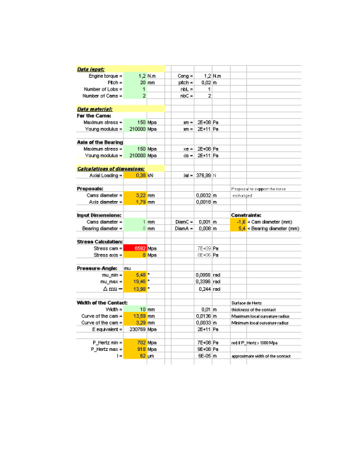
The GUI allows the user to test and visualize the cam profile generated.
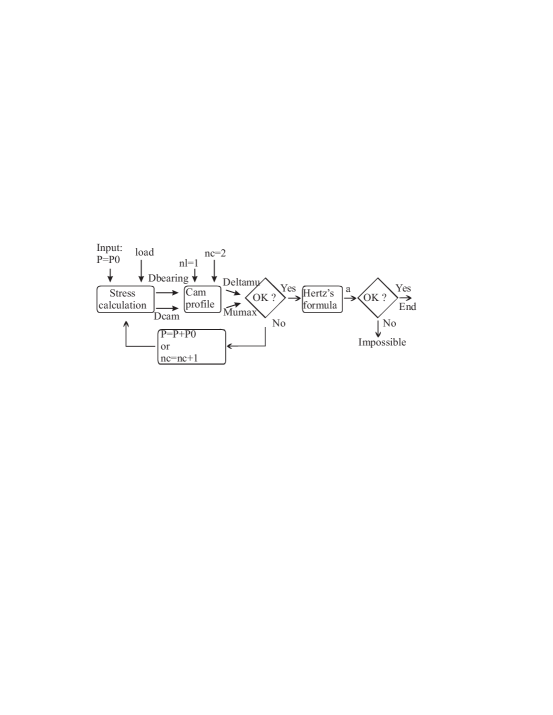
The algorithm underlying this GUI is shown in Fig. 8.
-
1.
The engine torque and the pitch are assigned by the user;
-
2.
for a given material of the camshaft and the roller, the minimum diameters are computed;
-
3.
the shape of the cam and the pressure angle are defined;
-
4.
in case the pressure angle is too high, the initial parameters and the number of cams are reassigned;
-
5.
in the other case, the Hertz pressure is evaluated to define the width of the cam and roller.
3 Influence of the design parameters on the pressure angle and the Hertz pressure
3.1 Analysis
The maximal value of the Hertz pressure depends on several parameters, namely, the number of conjugate cams, the material of the parts in contact, the geometry of the cams, and the load applied. The pressure angle can be optimized with regards to the number of cams and the shape of the cams [5]. There are many ways to minimize the Hertz pressure:
-
•
increase the number of conjugate cams in order to decrease the maximum pressure angle. Nevertheless, the number of simultaneous contact lines does not increase.
-
•
decrease the axial load. It can be done by increasing the pitch of the transmission.
-
•
choose a material with a lower Young modulus. However, when the material is more compliant, the maximum pressure acceptable decreases because the plastic domain occurs for smaller stress.
-
•
decrease the minimum radius of the cam. This feature will be used in the next section.
-
•
increase the width of the cam and the roller.
3.2 Design strategies
In this section, we present four strategies to minimize the radius of the cam:
-
1.
The lower , the distance between the cam axis and the bearing axis, the lower the maximum pressure angle and its range . This involves the removal of the bearing between the shaft and the cam and its offset on the base.
-
2.
With the first design strategy, the bearings can collide with the camshaft. In order to figure out this issue, the distance is increased. However, the advantages of the first solution are not maintained. In this case, a good compromise is to use two lines of followers on both sides of the cams.
-
3.
Another solution is to use cams assembled on the shaft. This design is more complex, but has some advantages. For instance, by means of a FEM, the optimal diameters of the camshaft and the roller are equal to 16 mm and 14 mm, respectively. For these values, and as illustrated in Fig. 9(a). With an inserted cam, we come up with a better design: , and 3 mm as illustrated in Fig. 9(b).
-
4.
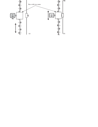
In the first design of the Slide-o-Cam transmission, the motor is fixed, as shown in Fig. 10(a). We have the following drawbacks:
-
•
For the same length of displacement, the length of the module is double because of guidance;
-
•
The effector being positioned at the end of the follower, the latter is subjected to bending;
-
•
Many parts are assembled between the motor and the effector. Consequently, the stiffness of the unit is smaller.
To figure out with these issues, the motor can be linked to the end-effector so that they can move altogether, as shown in Fig. 10(b).
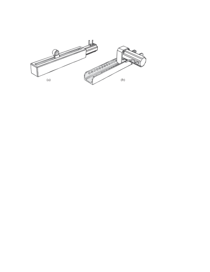
-
•
If we apply the previous design strategies, we will replace the classical ball-screws, Fig. 11(a), by a new transmission where the motor moves with the camshaft and the effector is attached to it, Fig. 11(b).
4 Implementation of the transmissions to the Orthoglide
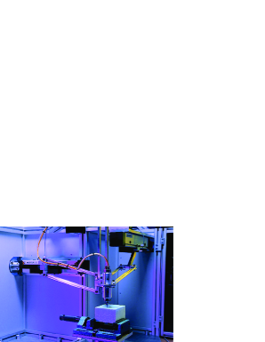
A motivation of this research work is to design a Slide-o-Cam transmission for high-speed machines. As mentioned in the introduction, this mechanism should be suitable for the Orthoglide, which is a low power machine tool, as shown in Fig. 12 [9]. Here is a list of its features:
-
-
ball screw engine torque N.m;
-
-
ball screw engine velocity to rpm;
-
-
ball screw pitch mm/turn;
-
-
axial static load N;
-
-
stiffness N/m.
Let us assume that the maximum stress that the shafts can support is equal to MPa. We can compute the minimum diameter of the bearing shaft and the cam shaft to transmit the load. The minimum diameter of the bearing shaft is equal to 1.8 mm. Likewise, the minimum diameter of the camshaft is equal to 3.75 mm.
Table 1 and Fig. 13 depict four design strategies applied to the Orthoglide. In case of high-speed operations, angular velocities of cams are higher than 50 rpm. Therefore, the pressure angle has to be smaller than 30∘. For instance, with case study (d) the Hertz pressure is a minimum but the pressure angle is a maximum.
From cases (a) to (d), the local radius of the cam increases from 0.08 mm to 1.6 mm. This feature verifies the assumption of section II.D related to the minimization of the Hertz pressure. For the optimal design, the Orthoglide can transmit the load with = 3.8 mm.
| Case # | ||||
|---|---|---|---|---|
| (a) | 786 MPa | 579 MPa | 1.13mm | |
| (b) | 933 MPa | 492 MPa | 0.08mm | |
| (c) | 732 MPa | 492 MPa | 1.44mm | |
| (d) | 689 MPa | 522 MPa | 1.6mm |
5 Acknowledgments
This research work was made in the context of an exchange between McGill University and Centrale Nantes, which allows Lucas Chabert to work six months in Montreal. Moreover, the authors would like to thank Prof. Jorge Angeles for his great help and good advice.
6 Conclusions
New design strategies were presented in this paper to minimize the Hertz pressure in the rollers and the cam of the Slide-o-Cam mechanism. A graphic user interface was developed to synthesize planar cam mechanisms, considering their physical constraints. The cam profiles generated can be used to realize CAD models.
The main contribution of this research work lies in the study of the influence of the pressure angle on the Hertz pressure. As a matter of fact, the smaller the pressure angle of a cam, the higher its Hertz pressure. In order to reduce the maximum Hertz pressure of a cam, we defined its parameters in order to keep the pressure angle smaller than .
References
- [1] González-Palacios, M.A. and Angeles, J., 2003, The design of a novel pure-rolling transmission to convert rotational into translational motion”, Journal of Mechanical Design, Vol. 125, pp. 205–207
- [2] Waldron, K. J. and Kinzel, G. L., 1999, Kinematics, Dynamics, and Design of Machinery, John Wiley & Sons, Inc., New York.
- [3] Angeles, J. and López-Cajún,C., 1991, Optimization of Cam Mechanisms, Kluwer Academic Publishers B.V., Dordrecht.
- [4] Carra, S., Garziera, R. and Pellegrini, M., 2004, “Synthesis of cams with negative radius follower and evaluation of the pressure angles,” Mechanism and Machine Theory, Vol. 34, pp. 1017–1032.
- [5] Renotte J., Chablat D. and Angeles J., 2004, “The Design of a Novel Prismatic Drive for a Three-DOF Parallel-Kinematics Machine,” ASME Design Engineering Technical Conferences, September - October 28-2, Salt Lake City, Utah, USA.
- [6] González-Palacios, M. A. and Angeles, J., 1993, Cam Synthesis, Kluwer Academic Publishers B.V., Dordrecht.
- [7] Lee, M.K., 2001, Design for Manufacturability of Speed-Reduction Cam Mechanisms, M.Eng. Thesis, Dept. of Mechanical Engineering, McGill University, Montreal.
- [8] Golovin A., Borisov A., Drozdova I., and Shuman B., 2005, “The simulating model of a gearing wear”, Moscow State Technical University named after M.E. Bauman, Moscow, Russia.
- [9] Chablat, D. and Wenger Ph., 2003, “Architecture Optimization of a 3-DOF Parallel Mechanism for Machining Applications, the Orthoglide,” IEEE Transactions on Robotics and Automation, Vol. 19/3, pp. 403–410, June.