A Delayed Choice Quantum Eraser
Abstract
This paper reports a “delayed choice quantum eraser” experiment proposed by Scully and Drühl in 1982. The experimental results demonstrated the possibility of simultaneously observing both particle-like and wave-like behavior of a quantum via quantum entanglement. The which-path or both-path information of a quantum can be erased or marked by its entangled twin even after the registration of the quantum.
pacs:
PACS Number: 03.65.Bz, 42.50.DvComplementarity, perhaps the most basic principle of quantum mechanics, distinguishes the world of quantum phenomena from the realm of classical physics. Quantum mechanically, one can never expect to measure both precise position and momentum of a quantum at the same time. It is prohibited. We say that the quantum observables “position” and “momentum” are “complementary” because the precise knowledge of the position (momentum) implies that all possible outcomes of measuring the momentum (position) are equally probable. In 1927, Niels Bohr illustrated complementarity with “wave-like” and “particle-like” attributes of a quantum mechanical object [1]. Since then, complementarity is often superficially identified with “wave-particle duality of matter”. Over the years the two-slit interference experiment has been emphasized as a good example of the enforcement of complementarity. Feynman, discussing the two-slit experiment, noted that this wave-particle dual behavior contains the basic mystery of quantum mechanics [2]. The actual mechanisms that enforce complementarity vary from one experimental situation to another. In the two-slit experiment, the common “wisdom” is that the position-momentum uncertainty relation makes it impossible to determine which slit the photon (or electron) passes through without at the same time disturbing the photon (or electron) enough to destroy the interference pattern. However, it has been proven [3] that under certain circumstances this common interpretation may not be true. In 1982, Scully and Drühl found a way around this position-momentum uncertainty obstacle and proposed a quantum eraser to obtain which-path or particle-like information without scattering or
otherwise introducing large uncontrolled phase factors to disturb the interference. To be sure the interference pattern disappears when which-path information is obtained. But it reappears when we erase (quantum erasure) the which-path information [3, 4]. Since 1982, quantum eraser behavior has been reported in several experiments [5]; however, the original scheme has not been fully demonstrated.
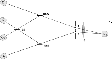
One proposed quantum eraser experiment very close to the 1982 proposal is illustrated in Fig.1. Two atoms labeled by A and B are excited by a laser pulse. A pair of entangled photons, photon 1 and photon 2, is then emitted from either atom A or atom B by atomic cascade decay. Photon 1, propagating to the right, is registered by a photon counting detector , which can be scanned by a step motor along its -axis for the observation of interference fringes. Photon 2, propagating to the left, is injected into a beamsplitter. If the pair is generated in atom A, photon 2 will follow the A path meeting with 50% chance of being reflected or transmitted. If the pair is generated in atom B, photon 2 will follow the B path meeting with 50% chance of being reflected or transmitted. Under the 50% chance of being transmitted by either or , photon 2 is detected by either detector or . The registration of or provides which-path information (path A or path B) of photon 2 and in turn provides which-path information of photon 1 because of the entanglement nature of the two-photon state of atomic cascade decay. Given a reflection at either or photon 2 will continue to follow its A path or B path to meet another 50-50 beamsplitter and then be detected by either detector or , which are placed at the output ports of the beamsplitter . The triggering of detectors or erases the which-path information. So that either the absence of the interference or the restoration of the interference can be arranged via an appropriately contrived photon correlation study. The experiment is designed in such a way that , the optical distance between atoms A, B and detector , is much shorter than , which is the optical distance between atoms A, B and detectors , , , and respectively. So that will be triggered much earlier by photon 1. After the registration of photon 1, we look at these “delayed” detection events of , , , and which have constant time delays, , relative to the triggering time of . It is easy to see these “joint detection” events must have resulted from the same photon pair. It was predicted that the “joint detection” counting rate (joint detection rate between and ) and will show interference pattern when detector is scanned along its -axis. This reflects the wave property (both-path) of photon 1. However, no interference will be observed in the “joint detection” counting rate and when detector is scanned along its -axis. This is clearly expected because we now have indicated the particle property (which-path) of photon 1. It is important to emphasize that all four “joint detection” rates , , , and are recorded at the same time during one scanning of along its -axis. That is, in the present experiment we “see” both wave (interference) and which-path (particle-like) with the same apparatus.
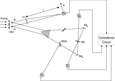
We wish to report a realization of the above quantum eraser experiment. The schematic diagram of the experimental setup is shown in Fig.2. Instead of atomic cascade decay, spontaneous parametric down conversion (SPDC) is used to prepare the entangled two-photon state. SPDC is a spontaneous nonlinear optical process from which a pair of signal-idler photons is generated when a pump laser beam is incident onto a nonlinear optical crystal [6]. In this experiment, the Argon ion pump laser beam is divided by a double-slit and incident onto a type-II phase matching [7] nonlinear optical crystal BBO () at two regions A and B. A pair of orthogonally polarized signal-idler photon is generated either from A or B region. The width of the SPDC region is about and the distance between the center of A and B is about . A Glen-Thompson prism is used to split the orthogonally polarized signal and idler. The signal photon (photon 1, either from A or B) passes a lens to meet detector , which is placed on the Fourier transform plane (focal plane for collimated light beam) of the lens. The use of lens is to achieve the “far field” condition, but still keep a short distance between the slit and the detector . Detector can be scanned along its -axis by a step motor. The idler photon (photon 2) is sent to an interferometer with equal-path optical arms. The interferometer includes a prism , two 50-50 beamsplitters , , two reflecting mirrors , , and a 50-50 beamsplitter . Detectors and are placed at the two output ports of the , respectively, for erasing the which-path information. The triggering of detectors and provide which-path information of the idler (photon 2) and in turn provide which-path information of the signal (photon 1). The electronic output pulses of detectors , , , and are sent to coincidence circuits with the output pulse of detector , respectively, for the counting of “joint detection” rates , , , and . In this experiment the optical delay () is chosen to be , where is the optical distance between the output surface of and detector , and is the optical distance between the output surface of the and detectors , , , and , respectively. This means that any information one can learn from photon 2 must be at least later than what one has learned from the registration of photon 1. Compared to the response time of the detectors, delay is good enough for a “delayed erasure”.
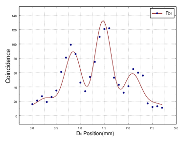
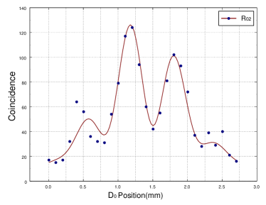
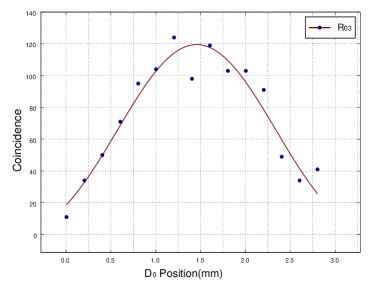
Figs.3, 4, and 5 report the experimental results, which are all consistent with prediction. Figs.3 and 4 show the “joint detection” rates and against the coordinates of detector . It is clear we have observed the standard Young’s double-slit interference pattern. However, there is a phase shift between the two interference fringes. The phase shift is explained as follows. Fig.5 reports a typical (), “joint detection” counting rate between and “which-path” (), against the coordinates of detector . An absence of interference is clearly demonstrated. There is no significant difference between the curves of and except the small shift of the center.
To explain the experimental results, a standard quantum mechanical calculation is presented in the following. The “joint detection” counting rate, , of detector and detector on the time interval , is given by the Glauber formula [8]:
| (1) | |||||
| (2) |
where is the detection time of , is the detection time of ) and are positive and negative-frequency components of the field at detectors and , respectively. is the entangled state of SPDC,
| (3) |
where , for the SPDC in which and are the frequency and wavevectors of the signal (), idler (), and pump (), respectively, and can be considered as constants, a single mode laser line is used for pump and and are creation operators for signal and idler photons, respectively. For the case of two scattering atoms, see ref. [3], and in the case of cascade radiation, see ref. [9], has a similar structure but without the momentum delta function. The functions in eq.(3) are the results of approximations for an infinite size SPDC crystal and for infinite interaction time. We introduce the two-dimensional function as in eq.(2),
| (4) |
is the joint count probability amplitude (“wavefunction” for short), where () is the optical distance between the output point on the BBO crystal and (). It is straightforward to see that the four “wavefunctions” , correspond to four different “joint detection” measurements, having the following different forms:
| (5) | |||
| (6) | |||
| (7) |
where as in Fig.1 the upper index of (A or B) labels the scattering crystal (A or B region) and the lower index of indicates different detectors. The different sign between the two amplitudes and is caused by the transmission-reflection unitary transformation of the beamsplitter , see Fig.1 and Fig.2. It is also straightforward to calculate each of the [10]. To simplify the calculations, we consider the longitudinal integral only and write the two-photon state in terms of the integral of and :
| (8) | |||
| (9) |
where a type-II phase matching crystal with finite length of is assumed. is a sinc-like function, . Using eqs. (4) and (9) we find,
| (10) | |||
| (11) |
where is the spectral transmission function of an assumed filter placed in front of the detector and is assumed Gaussian to simplify the calculation. To complete the integral, we define and , where and are the center frequencies of the SPDC, and is a small tuning frequency, so that still holds. Consequently, we can expand and around and to first order in :
| (12) | |||||
| (13) |
where and are recognized as the group velocities of the e-ray and o-ray at frequencies and , respectively. Completing the integral, the biphoton wavepacket of type-II SPDC is thus:
| (14) |
where we have dropped the indices. The shape of is determined by the bandwidth of the spectral filters and the parameter of the SPDC crystal, where . If the filters are removed or have large enough bandwidth, we have a rectangular pulse function .
It is easy to find that the two amplitudes in and are indistinguishable (overlap in both and ), respectively, so that interference is expected in both the coincidence counting rates, and ; however, with a phase shift due to the different sign,
If we consider “slit” A and B both have finite width (not infinitely narrow), an integral is necessary to sum all possible amplitudes along slit A and slit B. We will have a standard interference-diffraction pattern for and ,
| (15) | |||||
| (16) |
where is the width of the slit A and B (equal width), is the distance between the center of slit A and B, is the wavelength of the signal and idler, and is the focal length of lens . We have also applied the “far field approximation” for the signal and equal optical distance of the interferometer for the idler. After considering the finite size of the detectors and the divergence of the pump beam for further integrals, the interference visibility is reduced to the level close to the observation.
For the “joint detection” and , it is seen that the “wavefunction” in eq.(7) (which clearly provides “which-path” information) has only one amplitude and no interference is expected.
In conclusion, we have realized a quantum eraser experiment of the type proposed in ref. [3]. The experimental results demonstrate the possibility of observing both particle-like and wave-like behavior of a light quantum via quantum mechanical entanglement. The which-path or both-path information of a quantum can be erased or marked by its entangled twin even after the registration of the quantum.
This work was supported, in part, by the U.S. Office of Naval Research, the Army Research Office - the National Security Agency, the National Science Foundation, and the Welch Foundation. MOS wishes to thank Roland Hagen for helpful and stimulating discussions.
REFERENCES
- [1] N. Bohr, Naturwissenschaften, 16, 245 (1928).
- [2] R. Feynman, R. Leighton, and M. Sands, The Feynman Lectures on Physics, Vol. III, Addison Wesley, Reading (1965).
- [3] M.O. Scully and K. Drühl, Phys. Rev. A 25, 2208 (1982).
- [4] See Wheeler’s “delayed choice”, in Quantum Theory and Measurement, edited by J.A. Wheeler and W.H. Zurek, Princeton Univ. Press (1983).
- [5] A.G. Zajonc et al., Nature, 353, 507 (1991); P.G. Kwiat et al., Phys. Rev. A 49, 61 (1994); T.J. Herzog et al., Phys. Rev. Lett., 75, 3034 (1995); T.B. Pittman et al., Phys. Rev. Lett., 77, 1917 (1996).
- [6] D.N. Klyshko, Photon and Nonlinear Optics, Gordon and Breach Science, New York (1988); A. Yariv, Quantum Electronics, John Wiley and Sons, New York (1989).
- [7] In type-I SPDC, signal and idler are both ordinary rays of the crystal; however, in type-II SPDC the signal and idler are orthogonal polarized, i.e., one is ordinary ray and the other is extraordinary ray of the crystal.
- [8] R.J. Glauber, Phys. Rev. 130, 2529 (1963); 131, 2766 (1963).
- [9] M.O. Scully and M.S. Zubairy, Quantum Optics, Cambridge Univ. Press, Cambridge, UK (1997).
- [10] M.H. Rubin, D.N. Klyshko, and Y.H. Shih, Phys. Rev. A 50, 5122 (1994).