Ultraslow Propagation of Matched Pulses by Four-Wave Mixing in an Atomic Vapor
Abstract
We have observed the ultraslow propagation of matched pulses in nondegenerate four-wave mixing in a hot atomic vapor. Probe pulses as short as 70 ns can be delayed by a tunable time of up to 40 ns with little broadening or distortion. During the propagation, a probe pulse is amplified and generates a conjugate pulse which is faster and separates from the probe pulse before getting locked to it at a fixed delay. The precise timing of this process allows us to determine the key coefficients of the susceptibility tensor. The presence of gain in this system makes this system very interesting in the context of all-optical information processing.
pacs:
42.50.Gy, 42.65.YjSlow group velocities, valuable for all-optical signal processing, are obtained at a resonance peak of the transmission spectrum of a medium, and a number of different implementations of this principle have been demonstrated. They rely either on a reduction of the absorption, such as electromagnetically induced transparency (EIT) Kasapi et al. (1995), coherent population oscillations Bigelow et al. (2003), and dual absorption lines Camacho et al. (2006), or on a gain resonance, like stimulated Brillouin scattering Okawachi et al. (2005) and stimulated Raman scattering Sharping et al. (2005). To be useful in the context of all-optical signal processing, an optical delay line should be able to produce a fractional delay (defined as the ratio of the delay to the duration of the pulse) larger than unity with only modest absorption and pulse broadening. Recent developments Okawachi et al. (2005); Zhang et al. (2006); Jiang et al. (2006) have shown the benefits of using an amplifying medium to alleviate the absorption and distortion issues usually associated with slow light Matsko et al. (2005).
We have examined the group velocity reduction effects due to nondegenerate four-wave mixing (4WM) in hot rubidium vapor, and have obtained large fractional delays with almost no distortion. The presence of gain in this system makes it in principle possible to stack such delay lines and achieve fractional delays only limited by pulse broadening. Another notable feature of the amplification in the 4WM process is the generation of a conjugate pulse which is coupled to the probe and which propagates alongside it, similar to matched pulses in EIT systems Harris (1997). We have studied the interplay between the 4WM coupling of the probe and conjugate, and the Raman coupling of the probe and pump. This interplay leads to the ultraslow propagation of matched probe and conjugate pulses and to the enhancement of the 4WM gain. Such an enhancement, when applied to cross-phase modulation, is the key element of recent optical quantum information processing proposals Lukin and Imamoğlu (2000, 2001); Wang et al. (2006).
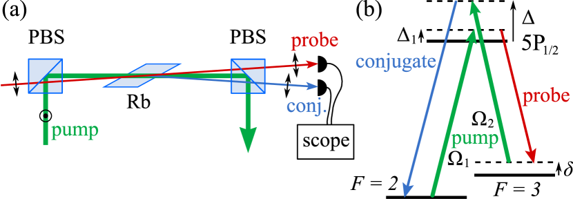
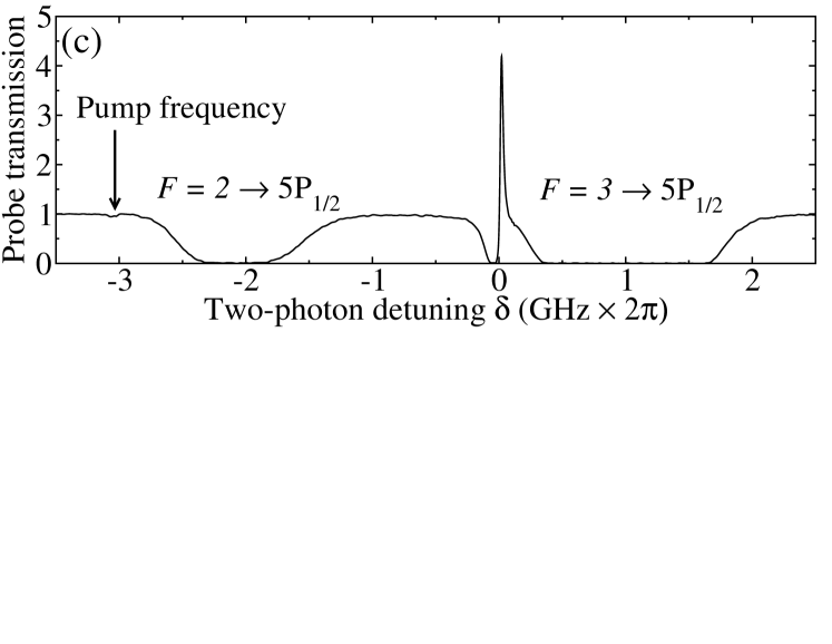
Our apparatus, which is essentially the same as the one described in Ref. McCormick et al. (2007), consists of a linearly polarized, continuous, strong (up to 280 mW) pump and a cross-polarized, pulsed, weak (0.5 mW) probe propagating at a small angle () through a 2.5 cm-long 85Rb cell heated to C-C (Fig. 1a). The pump and the probe are near resonant with a Raman transition between the two hyperfine electronic ground states of 85Rb, with a controllable detuning (Fig. 1b), and have radii of 600 m and 350 m, respectively. The residual 2-photon Doppler broadening due to the small angle is a few MHz. The detuning from the 5P1/2 excited state is MHz, and the peak pump intensity (up to W/cm2) is high enough to excite off-resonant Raman transitions with a detuning GHz from the excited state. The double-lambda Lukin et al. (1998) is closed by the conjugate beam which emerges on the other side of the pump from the probe, with the same polarization as the probe. The combination of the beam polarizations and the Zeeman substructure makes the system a four-level system (the two virtual excited states are orthogonal). The probe amplification is sharply resonant in , as shown in Fig. 1c, with a gain that can reach 30. The gain feature leads to a strong dispersion of the index of refraction and thus a low group velocity for the probe.
We measure the group velocity delay by recording the arrival time of a 70 ns-long (full width half maximum [FWHM]) gaussian probe pulse with and without the atomic medium (reference pulse). Figure 2a shows an example in which the parameters are set to provide a large probe gain (). By varying the two-photon detuning and the pump intensity, one can tune the probe delay and achieve a fractional delay larger than 0.5 such that the pulse remains gaussian and is broadened by less than 10% of its original width. This low level of distortion is remarkable in comparison with that seen in some EIT experiments Matsko et al. (2005). The maximum delay corresponds to a group velocity of , where is the speed of light in vacuum. It is in general possible to tune the pump intensity, the pump and probe detunings, and the temperature to achieve an overall gain of unity. Figure 2a also shows the record of the conjugate intensity. A striking feature is the emergence of the conjugate pulse before the probe pulse. This relative delay is a fundamental property of the dynamics of the system, and was predicted and observed in Refs. van der Wal et al. (2003); André (2005) in the case of resonance on the “lower” lambda transition ().
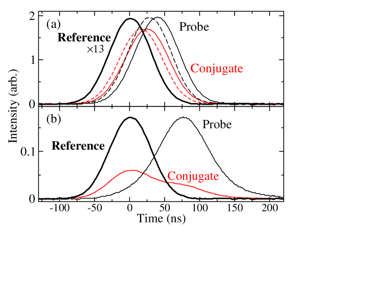
Larger delays, shown in Fig. 2b, can be achieved by setting between the gain peak and the Raman absorption dip present at (see Fig. 1c). The competition between large amplification and large absorption leads to some complex dynamics which can result in pulse breakup, in a similar fashion to the dual-field solitons predicted to exist in three-level systems Konopnicki and Eberly (1981). In this paper, we restrict ourselves to the regions of low absorption where, in spite of complications associated with the use of hot atoms, our system can be consistently described over a broad range of parameters by the simple concepts developed in the theory of Refs. Lukin et al. (2000); André (2005).
We neglect the hyperfine splitting of the excited state. Averaged over the Zeeman substructure, the dipole moments of all four transitions are equal, which gives and , the peak resonant Rabi frequencies of the pump for the “lower” and the “upper” lambda respectively, the same value, denoted . The double-lambda system in its ideal incarnation operates in the limit and has the following crucial features. First, a ground state coherence is established by the “lower”, more resonant lambda. The coherence has a lifetime , limited by magnetic fields, collisions and the transit time in the laser beams, and corresponds to a dark state in which the absorption of the probe is reduced (EIT). Second, the “upper”, less resonant lambda slightly perturbs this coherence and creates a resonant atomic polarization at the probe and conjugate frequencies via 4WM, while keeping the population in the excited state near zero. The dynamics of the system can thus be broken down into two intertwined processes: EIT and 4WM.
In the limit of a strong pump and low pump depletion, most of the atomic population is in the ground state , and the Fourier components and of the slowly-varying envelopes of the probe and conjugate fields (of wavevectors and ) obey the equations Lukin et al. (2000); André (2005):
| (1) | |||||
| (2) |
We assume perfect phase matching. In the limit of , , and , (where MHz is the linewidth of the atomic transition), the coefficients in Eqs. (1) and (2) are Lukin et al. (2000) and . Here, , , is the atomic density, and is the average dipole moment acting on the probe and the conjugate.
The interpretation of Eqs. (1) and (2) is straightforward. The probe field is slowed down by a factor due to the EIT interaction with the pump [second drive term on the right-hand side of Eq. (1)]. The EIT resonance is light-shifted by the pump on the “upper” lambda and occurs at . In addition, and are cross-coupled with a coupling constant , responsible for the 4WM amplification. The presence of highlights the role of the longer interaction time due to the slow-down effect in obtaining a sizeable nonlinear coupling Lukin and Imamoğlu (2001). The other factor in , the so-called Raman bandwidth , is the Rabi frequency of a fictitious resonant Raman transition driven on both legs by the pump field and with an intermediate Raman detuning . As shown by the absence of any dependence on , the 4WM dynamics is dominated by the “upper” lambda, which acts as a bottleneck. The propagation equations are asymmetrical. The imaginary part of the coefficient of the direct term for the conjugate [Eq. (2)], corresponding to a slow-light effect, is negligible compared to the same term for the probe because Lukin et al. (2000). The real part, corresponding to a Raman amplification, scales as and is negligible compared to the cross-term which scales as Lukin et al. (2000); André (2005). As a result, in the absence of the 4WM coupling (“bare” fields), the probe and the conjugate propagate at velocities and , respectively. The finite decoherence translates into a small absorption of the probe.
Our system departs from the ideal case described by the expressions of and given above in many respects. Unlike the experiments described in Refs. Lukin et al. (2000); van der Wal et al. (2003); André (2005), which were performed with a resonant probe and a weak pump, our probe is tuned to the side of the Doppler profile, in an already almost transparent region. As a result, the position of the gain peak is not tied as closely to a narrow EIT window. It depends on the balance between the losses, which include the Raman absorption dip and the absorption from the Doppler broadened 1-photon transition, and the 4WM gain. Factors influencing the peak position are the spread of values for due to the Doppler broadening, the spread of values for and due to the Zeeman degeneracy, the contribution of the usual dispersion of the Doppler broadened vapor to the slow-down of the probe, and the only approximate phase matching. In practice, this means that the position of the gain peak varies by up to 20 MHz depending on parameters like the temperature, and the probe intensity.
In spite of the added complexity and the difficulty of directly calculating and , we assume that the propagation equations (1) and (2) are still valid over most of the resonance peak, provided that the peak is at , and that . Solving them in the limit and starting from a probe field and no conjugate field, one finds:
| (3) | |||||
| (4) |
where and . Since , is real. As expected, past an initial linear growth of the conjugate, both fields grow exponentially in distance with as the linear gain coefficient. In the limit , one has .
The solutions also contain information about the propagation delay. Equations (3) and (4) show that the fields accumulate a phase across the medium, denoted . The main contribution to the group delay for both fields comes from the first exponential and gives a common delay . In other words, the probe and the conjugate are slowed down by half the “bare” slow-down factor . The probe experiences an extra delay due to the second term in Eq. (3). At large gain, the cosh and sinh functions are equal and the additional delay is . At low gain, a first order expansion in gives . The picture emerging from this analysis is the following: the conjugate pulse is created without delay by the probe and travels at a velocity (). The probe pulse travels initially at a velocity and then locks onto the conjugate by accelerating to when the delay reaches (at a gain close to 2).
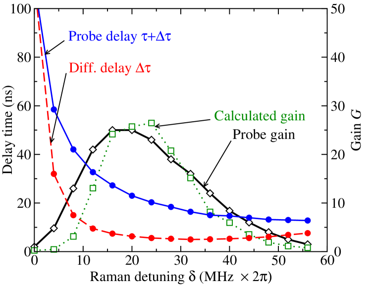
We test this interpretation by first scanning the two-photon detuning , using 120 ns-long (FWHM) probe pulses and a pump power of 280 mW, which corresponds to a spread of of 10 MHz around zero and to MHz. Figure 3 shows the measured gain, the probe delay , which includes the contribution of all the retardation effects, and the differential delay . The contribution to the probe delay of the usual dispersion effect, which is measured with the pump intensity strongly reduced, is found to be ns. From the experimental data and the theoretical expressions of and , one can deduce a value of and for each , in the limit of large gain and small . Inserting these values into Eq. (3) (with ) and adjusting to (making the linear losses equal to of the peak linear gain) 111This value of is sensitive to the timing errors ( ns) and is only an indication of the order of magnitude. For , it corresponds to 15% of absorption, which is compatible with the level of squeezing measured in Ref. McCormick et al. (2007). , one can reproduce the gain curve with reasonable accuracy. For our parameters, the EIT resonance is light-shifted to MHz, close to the observed gain maximum ( MHz). It can be shown that in the above calculations, the approximation is valid as long as ( for our beam parameters). For larger than a few , that is to say in the wings of the gain peak, the approximation is expected to break down.
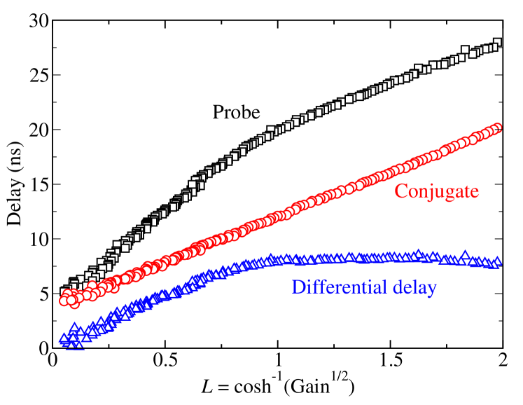
Next, we directly observe the locking between the probe and the conjugate during the propagation. It is impractical to continuously vary the distance of propagation and we instead vary the atomic density via the temperature, which is equivalent. Indeed, and are proportional to through their dependence on , and changing is like renormalizing in the solutions (3) and (4). According to (3), the renormalized propagation length is related to the probe intensity gain by . The detuning is set to 15 MHz, near the gain maximum, the pump power is still set to 280 mW, and the measured delays as a function of the renormalized distance for a temperature scan of C around C are shown in Fig. 4. The two regimes of propagation are very clear. First, the pulses separate in time, and second they lock to each other at a fixed delay. The time offset at the origin is not well understood. A direct evaluation of in the ideal case using our beam parameters gives a value of 7 ns, comparable to the one measured near the gain maximum (see Fig. 3). We checked qualitatively that increases when the pump intensity decreases. It is worth noting that the detail of the low-gain transient regime depends on the initial conditions. For instance, swaping the frequencies of the probe and the conjugate would lead to an initial propagation in which the probe travels at a velocity while the conjugate travels at a velocity .
Finally, an important feature of the model is that the gain saturates with the pump intensity. For a gain peak location and a decoherence of the order of , saturates when MHz . In agreement with this prediction, we observe that starts saturating at our operating intensity.
To conclude, we have observed the ultraslow propagation of probe and conjugate pulses with matched shapes and group velocities through a rubidium vapor. The study of the coupled propagation gives access to the atomic dynamics through a simple model that reflects a few key concepts. Although the hypothesis of the model does not match precisely the conditions of the experiment, our findings on slow propagation and delay locking of the probe and conjugate pulses are generic to the double-lambda system. The quality of the retardation effect in terms of fractional delay and absence of loss and distortion suggests the possible existence of a dual-field soliton, which would be the result of higher order terms in the propagation equations. Such a soliton has been predicted in related 4WM schemes Deng et al. (2005).
It should also be noted that this double-lambda scheme is known to generate relative-number squeezed twin beams McCormick et al. (2007) (as well as correlated photons Kolchin et al. (2006)). Extending this semi-classical pulse theory to the quantum correlated beams raises two comments. First, as pointed out in Ref. André (2005), the time lag between the probe and the conjugate should be the limiting factor to the squeezing bandwidth observed in Ref. McCormick et al. (2007). Second, the system could be used with gain close to unity to slow light in the quantum regime, while preserving nonclassical correlations, possibly more efficiently than with EIT alone Akamatsu et al. (2006).
CFM was supported by an IC Postdoctoral Fellowship. We acknowledge very helpful discussions with A. M. Marino.
References
- Kasapi et al. (1995) A. Kasapi et al., Phys. Rev. Lett. 74, 2447 (1995).
- Bigelow et al. (2003) M. S. Bigelow, N. N. Lepeshkin, and R. W. Boyd, Science 301, 200 (2003).
- Camacho et al. (2006) R. M. Camacho, M. V. Pack, and J. C. Howell, Phys. Rev. A 73, 063812 (2006).
- Okawachi et al. (2005) Y. Okawachi et al., Phys. Rev. Lett. 94, 153902 (2005).
- Sharping et al. (2005) J. Sharping, Y. Okawachi, and A. Gaeta, Opt. Express 13, 6092 (2005).
- Zhang et al. (2006) J. Zhang, G. Hernandez, and Y. Zhu, Opt. Lett. 31, 2598 (2006).
- Jiang et al. (2006) K. J. Jiang, L. Deng, and M. G. Payne, Phys. Rev. A 74, 041803(R) (2006).
- Matsko et al. (2005) A. Matsko, D. Strekalov, and L. Maleki, Opt. Express 13, 2210 (2005).
- Harris (1997) S. E. Harris, Phys. Today 50, 36 (1997), and references therein.
- Lukin and Imamoğlu (2000) M. D. Lukin and A. Imamoğlu, Phys. Rev. Lett. 84, 1419 (2000).
- Lukin and Imamoğlu (2001) M. D. Lukin and A. Imamoğlu, Nature 413, 273 (2001).
- Wang et al. (2006) Z.-B. Wang, K.-P. Marzlin, and B. C. Sanders, Phys. Rev. Lett. 97, 063901 (2006).
- McCormick et al. (2007) C. F. McCormick, V. Boyer, E. Arimondo, and P. D. Lett, Opt. Lett. 32, 178 (2007).
- Lukin et al. (1998) M. D. Lukin et al., Phys. Rev. Lett. 81, 2675 (1998).
- van der Wal et al. (2003) C. H. van der Wal et al., Science 301, 196 (2003).
- André (2005) A. André, Ph.D. thesis, Harvard University (2005).
- Konopnicki and Eberly (1981) M. J. Konopnicki and J. H. Eberly, Phys. Rev. A 24, 2567 (1981).
- Lukin et al. (2000) M. D. Lukin, P. R. Hemmer, and M. O. Scully, Adv. At., Mol., Opt. Phys. 42, 347 (2000), note the change in the definition of .
- Deng et al. (2005) L. Deng et al., Phys. Rev. E 72, 055601(R) (2005).
- Kolchin et al. (2006) P. Kolchin et al., Phys. Rev. Lett. 97, 113602 (2006).
- Akamatsu et al. (2006) D. Akamatsu et al. (2006), eprint quant-ph/0611097.