Error-resistant Single Qubit Gates with Trapped Ions
Abstract
Coherent operations constitutive for the implementation of single and multi-qubit quantum gates with trapped ions are demonstrated that are robust against variations in experimental parameters and intrinsically indeterministic system parameters. In particular, pulses developed using optimal control theory are demonstrated for the first time with trapped ions. Their performance as a function of error parameters is systematically investigated and compared to composite pulses.
pacs:
03.67.Lx, 45.50.ctIn order to experimentally implement a device capable of performing fault-tolerant universal quantum computation (QC), quantum gate operations involving one or multiple qubits have to be carried out with demandingly high accuracy (see, for instance, Aliferis06 ; Knill06 ). According to recent theoretical investigations, the experimentally required accuracy of quantum gates for fault-tolerant universal quantum computation no longer seems daunting or even prohibitive Knill06 . But still, the desired error probability per gate (EPG) should be as small as possible in order to keep the experimental overhead necessary for quantum computation within a feasible limit. Thus a low error probability is prerequisite for scalable fault-tolerant QC.
Any quantum algorithm can be decomposed into a sequence of unitary operations applied to individual qubits (single-qubit gate) and conditional quantum dynamics with at least two qubits Barenco95 . Multi-qubit gates (involving two or more qubits) are synthesized by applying a sequence of elementary unitary operations on a collection of qubits. Each of these elementary operations is often similar, or identical, to what is needed for single-qubit gates, and therefore each operation has to be implemented with an error probability well below the tolerable EPG characterizing the full gate operation.
If electrodynamically trapped ions are used as qubits, then a unitary operation amounts to letting ions interact with electromagnetic radiation with prescribed frequency, phase, amplitude, and duration of interaction in order to implement quantum gates. Recently, impressive experimental progress was demonstrated in entangling up to eight ions, and performing 2-qubit quantum gates Leibfried05 ; SchmidtKaler03 ; Leibfried03 . Architectures allowing for scalable QC with trapped ions have been proposed (e.g., Kielpinski02 ), and building blocks necessary for achieving this ambitious goal are currently being investigated using various types of ions.
The error budget, for instance, of the geometrical phase gate demonstrated in Leibfried03 is dominated by the frequency and amplitude uncertainty of the laser light field. These errors are also responsible for a part of the EPG of the controlled-NOT gate reported in SchmidtKaler03 . If an ”ion spin molecule”, that is, trapped ions coupled via a long range spin-spin interaction, is to be used for quantum information processing, then the exact transition frequency of a particular ionic qubit depends on the internal state of other ions Wunderlich02 . Therefore, here too, it is important to have quantum gates at hand that are insensitive to the detuning of the radiation driving the qubit transition.
Here, we demonstrate single qubit gates with trapped ions that are robust against experimental imperfections over a wide range of parameters. In particular it is shown that errors caused by an inaccurate setting of either frequency, amplitude, or duration of the driving field, or of a combination of these errors are tolerable (in terms of a desired accuracy of quantum gates) when a suitable sequence of radiation pulses is applied instead of, for instance, a single rectangular -pulse. Thus an essential prerequisite for scalable quantum computation with trapped ions is demonstrated.
We shall show results of using shaped pulses which were developed using optimal control theory. Optimal control theory relies on a generalization of the classical Euler-Lagrange formalism. Using discrete rather than continuous trajectories in the configuration space of the quantum mechanical system, and constraining the trajectories to satisfy the Bloch equations, the cost function to be optimized, is the transfer efficiency over a range of frequency detunings between qubit and applied radiation and amplitudes of the radiation Skinner03 . In addition, composite pulses are realized here that are specifically designed to tackle off-resonance errors, or designed to tackle pulse length errors or power discrepancies of the driving field Cummins03 .
The two level quantum mechanical system used as qubit is realized on the S1/2(F=0) S1/2(F=1, mF=0) transition in a single 171Yb+ ion with Bohr frequency confined in a miniature Paul trap (diameter of 2 mm), driven by microwave radiation with frequency close to GHz and Rabi frequency kHz. The time evolution of the qubit is virtually free of decoherence, that is, transversal and longitudinal relaxation rates are negligible, and is determined in a rotating frame after the rotating wave approximation, by the semi-classical Hamiltonian Here, are the atomic raising/lowering operators, is a Pauli matrix, and is the detuning of the applied radiation with respect to the atomic transition. Imperfect preparation of the state by optical pumping, limited here the purity of the initially prepared state, such that the initial density matrix (before coherent interaction with microwave radiation) is given by with typical values and .
The ion is produced from its neutral precursor by photoionization using a diode laser operating near 399 nm. Laser light near 369 nm driving resonantly the S1/2 F=1 P1/2 F=0 transition in Yb+ is supplied by a frequency doubled Ti:Sa laser, and serves for cooling and state selectively detecting the ion. A diode laser delivers light near 935 nm and drives the D3/2- transition to avoid optical pumping into the metastable D3/2 state during the cooling and detection periods (for details see Wunderlich03 ). For quantifying errors in detuning we will use the scaled detuning, whereas errors in pulse area shall be represented by , where with the desired pulse area, and the actual pulse area, when or are not set perfectly. The fidelity of the qubit state that is obtained after applying a microwave pulse is given by with being the state that would be obtained, if the pulse were perfect. Thus, for a -pulse the fidelity is given by . Impure initial preparation () limits the maximum fidelity that can be obtained with a -pulse to . In order to determine the fidelity of the state obtained after a gate that is supposed to leave the qubit with a well defined phase (e.g. a -pulse), the phase needs to be determined in addition to . A Ramsey-type experiment allows for measuring both angles: First an ideal Ramsey sequence is carried out (i.e. two successive ideal -pulses with varying phase of the second pulse) yielding interference fringes in the population of state , as a function of . Then, the first -pulse is replaced by a possibly non-ideal pulse sequence leaving the qubit in state , and again interference fringes, are recorded. Now the population detected in state is given by , and from a fit of the data one obtains and .
The basic measurement sequence (labeled sequence A) for determining the fidelity as a function of and of a shaped pulse that ideally gives a rotation with is as follows: i) A single ion is prepared in the state by optical pumping through illumination with 369 nm light for 20ms. ii) A microwave shaped pulse with controlled error, that is, known values of and , is applied. iii) Again, the ion is illuminated for 4 ms with 369 nm light for state selective detection. iv) The ion is laser cooled by applying microwave and laser radiation simultaneously. This sequence comprising steps i) through iv) is then repeated (sequence B), except that in step ii), for direct comparison, the shaped pulse is replaced by a rectangular pulse that would give , if . Then, i) through iv) is repeated again (sequence C) with an ideal (i.e., ) rectangular pulse to control state selective detection in each measurement cycle. Finally, i) through iv) is repeated a fourth time (sequence D) leaving out step ii) in order to monitor the initial preparation in terms of the coefficient . Typically, the full procedure (sequences A through D) outlined here is repeated 700 times for a given pair of and values.


When measuring the performance of shaped pulses and pulse sequences that ideally yield a rotation of and, for instance, , then the basic sequence, A’ is as described above, except that in step ii) two ideal () pulses are applied, the second one with variable phase (this yields Ramsey fringes as a reference). Then, sequence B’ is performed by replacing the first pulse in step ii) by a shaped pulse with controlled error. Sequence C’ is obtained by replacing the first pulse in ii) with a rectangular pulse subject to the same errors as the shaped pulse in B’. Sequences A’ through C’ are repeated 20 times while increasing the value of by . Then sequences C and D are appended and the complete procedure is repeated 50 times. As an example, Fig. 1 upper panels illustrates how angles , were determined for a specific pair of and values.
A completed measurement returns two grids of fidelities with the points on each grid defined by different values of and . One grid corresponds to a simple pulse (obtained from sequences B or C’), that is, the amplitude as a function of time has a rectangular shape with the desired pulse area, . This pulse results in a perfect rotation by an angle only for and . The second grid of fidelities corresponds to a shaped or composite pulse (obtained from sequence A or B’). In the experimental results shown below, crossing points between gridlines represent measurement points. The shaded areas are obtained by linear interpolation between points.
The pulses developed using Optimal Control Theory and demonstrated here were designed for off-resonant errors described by , power variations up to , Rabi frequency kHz, and are made of s steps. In each step, in general, amplitude and phase of the radiation is changed. As an example the time evolution of phase and amplitude of a shaped pulse consisting of 645 individual steps is shown in Fig. 1 Luy04 . This pulse is supposed to yield a rotation of that is robust against variations in and .
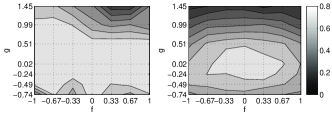

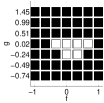
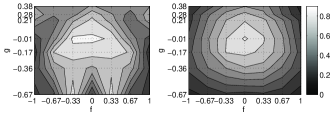
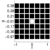
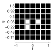
The experimentally determined fidelity of this shaped pulse as a function of and is displayed in Fig. 2. For reference, Fig. 2 also shows the experimental fidelity obtained from a simple rectangular gate for the same parameter range. For the simple pulse yields the maximum fidelity , and the range of and for which is indicated in Fig. 2 lower panel by white rectangles. The same maximum fidelity, , is also reached using the shaped pulse. However, this maximum value is maintained over a much wider parameter range as is evident from Fig. 2, thus demonstrating the robustness of the shaped pulse against experimental errors and intrinsic imperfections.
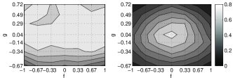
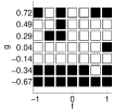

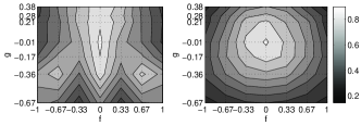
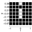
Fig. 3 displays the experimental fidelity obtained by using a shaped -pulse consisting of 445 steps with variable phase and amplitude subject to controlled errors. Again, a rectangular pulse serves as an experimental reference giving a maximum fidelity for that rapidly decreases for increasing or . The shaped pulse, in contrast, maintains the maximal possible fidelity over a wide range of parameters as is evident in Fig. 3. A shaped -pulse consisting of 835 steps was also implemented resulting in a parameter area indicating robustness against errors that extends even further (not shown).
If one uses shaped pulses obtained from optimal control theory, even with parameters that considerably deviate from their ideal values, one still attains accurate performance of single qubit gates. Now, we compare the performance of these pulses to some composite pulses that have been devised to be effective against off-resonance, amplitude, and pulse length errors. The resulting fidelity grids were measured by sequentially performing the composite case and the simple case for each point on the grid, and then repeating 300 times. In terms of the previously used description, sequence A and sequence B are performed for each point on the grid, they are followed by C and D, then the complete measurement procedure is performed 300 times.
The composite pulse of type CORPSE(Compensation for Off-Resonance with a Pulse Sequence) was derived with the aim of combatting off-resonant errors Cummins03 . It consists of three pulses where the first and the third pulses have equal phase values and the phase of the second pulse differs by . The nutation angles of the three pulses making up a composite pulse are Indeed, as shown in Fig. 4 upper panel the CORPSE -pulse extends the experimentally determined range of detuning over which a fidelity () is maintained as compared to the rectangular pulse shown on the right of Fig. 4. However, for compensating pulse area errors this pulse sequence is less effective as is also evident from Fig. 4.


The SCROFOLOUS (Short Composite ROtation For Undoing Length Over and Under Shoot) pulse was derived with the aim of compensating for pulse area errors. These pulses were derived by restricting the phase and and nutation angles such that with and unbound. The angles are chosen such that once again the fidelity is least effected by the presence of errors Cummins03 . For a -pulse these angles are . We show in Fig. 4 lower panel that errors in pulse area caused by power fluctuations are well compensated for. On the other hand, detuning errors have the same detrimental effect as is the case with a rectangular pulse. Composite pulses, with g describing time errors rather than amplitude errors were also implemented (not shown).
The BB1 (Broadband) composite pulse comprises a sequence . When the desired rotation is R(), the complete rotation can be performed as or . The measurement procedure follows the procedure outlined above for the shaped -pulse. Shown in Fig. 5 are the results of using the BB1 composite pulse with . The experimental data show that BB1 is effective for compensation of errors in both detuning and pulse area. The parameter range over which error resistant pulses are effective is greater than that of a simple pulse but is more restricted than with the shaped pulse shown in Fig. 2.


A comparison of the performance of shaped pulses developed using optimal control theory with simple rectangular pulses or composite pulses reveals an evident advantage of these shaped pulses in terms of robustness against experimental errors and indeterministic system parameters, while the lengths of both types of pulses are comparable (here, with kHz, for instance the pulse in Fig. 3 takes 223 s compared to 217 s for a CORPSE pulse of Fig. 4). This will make shaped pulses based on optimal control theory an important tool in order to achieve quantum gates with trapped ions with low error probability and thus come a step closer to fault-tolerant quantum computing.
We acknowledge discussions with S. Glaser, T. Schulte-Herbrueggen, C. Weiß, who also supplied simulation software, and support from the European Union IP QAP.
References
- (1) P. Aliferis, D. Gottesman, and J. Preskill, Quant. Inf. Comp. 6, 97 (2006).
- (2) E. Knill, Nature 434, 39 (2005).
- (3) A. Barenco et al., Phys. Rev. A, 52, 3457 (1995); For certain quantum computational tasks, gates that simultaneously act on more than two qubits have been shown to be more efficient than the use of two-qubit gates.
- (4) D. Leibfried et al., Nature 438, 639 (2005); H. Häffner et al., ibid. p. 643 (2005); P.C. Haljan et al., Phys. Rev. A 72, 062316 (2005); J.P. Home et al., New J. Phys. 8, 188 (2006).
- (5) F. Schmidt-Kaler et al., Nature 422, 408 (2003).
- (6) D. Leibfried et al., Nature 422, 412 (2003).
- (7) D. Kielpinski, C. Monroe, D. J. Wineland, Nature 417, 709 (2002).
- (8) Chr. Wunderlich, in Laser Physics at the Limit (Springer, Heidelberg, 2002), p. 261; available as quant-ph/0111158; F. Mintert, Chr. Wunderlich, Phys. Rev. Lett. 87, 257904 (2001); D. Mc Hugh, J. Twamley, Phys. Rev. A 71, 012315 (2005).
- (9) T.E. Skinner, T.O. Reiss, B. Luy, N. Khaneja and S. Glaser, J. Mag. Res. 163, 8 (2003).
- (10) H. Cummins, G. Llewellyn, and J. Jones, Phys. Rev. A 67, 042308 (2003).
- (11) K. Kobzar, T.E. Skinner,N.Khaneja, S. Glaser and B. Luy, J. Mag. Res. 170, 8, (2003).
- (12) Chr. Wunderlich and Chr. Balzer, Adv. At. Mol. Opt. Phys. 49, 293 (2003).