Realization of Wheeler’s delayed-choice interference experiment with a single-photon source and space-like separation.
Experimental realization of Wheeler’s delayed-choice GedankenExperiment
V. Jacques1, E Wu1,2, F. Grosshans1, F. Treussart1, P. Grangier3, A. Aspect3, and J.-F. Roch3,∗
1Laboratoire de Photonique Quantique et Moléculaire, ENS de Cachan, UMR CNRS 8537, Cachan, France
2Key Laboratory of Optical and Magnetic Resonance Spectroscopy, East China Normal University, Shanghai, China
3Laboratoire Charles Fabry de l’Institut d’Optique, UMR CNRS 8501, Orsay, France
∗To whom correspondence should be addressed; E-mail: roch@physique.ens-cachan.fr
The quantum “mystery which cannot go away” (in Feynman’s words) of wave-particle duality is illustrated in a striking way by Wheeler’s delayed-choice GedankenExperiment. In this experiment, the configuration of a two-path interferometer is chosen after a single-photon pulse has entered it : either the interferometer is closed (i.e. the two paths are recombined) and the interference is observed, or the interferometer remains open and the path followed by the photon is measured. We report an almost ideal realization of that GedankenExperiment, where the light pulses are true single photons, allowing unambiguous which-way measurements, and the interferometer, which has two spatially separated paths, produces high visibility interference. The choice between measuring either the open or closed configuration is made by a quantum random number generator, and is space-like separated — in the relativistic sense — from the entering of the photon into the interferometer. Measurements in the closed configuration show interference with a visibility of 94%, while measurements in the open configuration allow us to determine the followed path with an error probability lower than 1%.
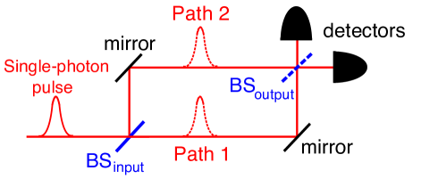
Young’s double-slit experiment, realized with particles sent one at a time through the interferometer is at the heart of Quantum Mechanics (?). The striking feature is that the phenomenon of interference, interpreted as a wave following simultaneously two paths, is incompatible with our common sense representation of a particle which implies to follow one route or the other but not both. Several true single-photon interference experiments (?, ?, ?, ?, ?) have clearly confirmed the wave-particle duality of the lightfield. To understand their meaning, consider the single-photon interference experiment sketched in Fig.1. In the closed interferometer configuration, a single-photon pulse is split by a first beamsplitter of a Mach-Zehnder interferometer and travels through it until a second beamsplitter recombines the two interfering arms. When the phase shift between the two arms is varied interference appears as a modulation of the detection probabilities at output ports 1 and 2 respectively as and . This result is the one expected for a wave, and as Wheeler pointed out, “[this] is evidence…that each arriving light quantum has arrived by both routes” (?). If beamsplitter is removed (open configuration), each detector D1 or D2 on the output ports is then associated to a given path of the interferometer, and — provided one uses true single-photon light pulses, “[either] one counter goes off, or the other. Thus the photon has traveled only one route” (?). Such an experiment supports Bohr’s statement that the behavior of a quantum system is determined by the type of measurement performed on it (?). Moreover, it is clear that for the two complementary measurements considered here, the corresponding experimental settings are mutually exclusive, i.e. the beamsplitter cannot be simultaneously inserted and removed.
In experiments where the choice between either setting is made long in advance, one could reconcile Bohr’s complementarity with Einstein’s local conception of the physical reality. Indeed, when the photon enters the interferometer, it could have received some “hidden information” on the chosen experimental configuration and could then adjusts its behavior accordingly (?). In order to rule out that too naive interpretation of quantum mechanical complementarity, J. A. Wheeler proposed the “delayed-choice” GedankenExperiment in which the choice of which property will be observed is made after the photon has passed the first beamsplitter . “Thus one decides the photon shall have come by one route or by both routes after it has already done its travel” (?).
Since Wheeler’s proposal, several pioneering delayed-choice experiments have been reported (?, ?, ?, ?, ?, ?). However, none of them fully followed the original scheme, demanding to use single-particle quantum state and to achieve space-like separation between the choice of the performed measurement and the entering of the particle into the interferometer. We report here the realization of such a “delayed-choice” experiment in a scheme very close to the ideal original proposal as described on Fig.1. The choice to insert or remove the beamsplitter is randomly decided, using a Quantum Random Number Generator (QRNG). The QRNG is located close to the output beamsplitter , and far enough from the input so that no information about the choice can reach the photon before it passes through the input beamsplitter .
Our single-photon source, previously developed for quantum key distribution (?, ?) is based on the pulsed, optically excited photoluminescence of a single N-V color center in a diamond nanocrystal (?). At the single-emitter level, these photoluminescent centers, which can be individually adressed using confocal microscopy (?), have shown unsurpassed efficiency and photostability at room temperature (?, ?). In addition it is possible to obtain single photons with a well defined polarization (?). (See supplementary information for technical details.)
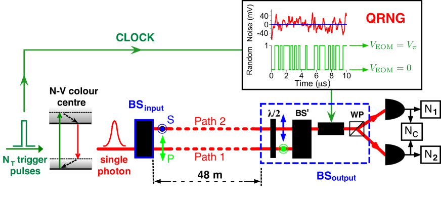
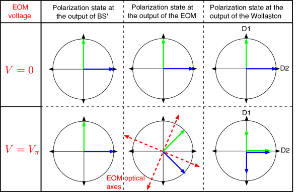
In order to fulfill the requested relativistic separation condition, we use a 48-meter-long polarization interferometer with two spatially separated paths (Fig.2). Single photons, linearly polarized at from the eigenpolarizations of the polarizing beamsplitter , are split into two components that travel along separated paths. The choice to recombine or not the two paths of the interferometer is done in two steps. First, the two beams, which are spatially separated and orthogonally polarized, are overlapped by a polarizing beamsplitter BS′, but can still be unambiguously identified by their polarization. Then, the choice between the two configurations closed or open is made with the fast electro-optical modulator (EOM) shown on Fig.2, followed by a Wollaston prism. When no voltage is applied to the EOM, the situation corresponds to the removal of BSoutput, and the two paths remain uncombined (open configuration of Fig.1). Each detector D1 or D2 is then associated to a specific path, respectively path 1 or path 2. When the EOM half-wave voltage is applied, the two orthogonally polarized beams which have traveled along different paths are recombined by the wollaston prism. We then have the closed interferometer configuration of Fig.1.
The space-like separation between the choice of the measurement and the passage of the photon at the input beamsplitter BSinput is achieved using a
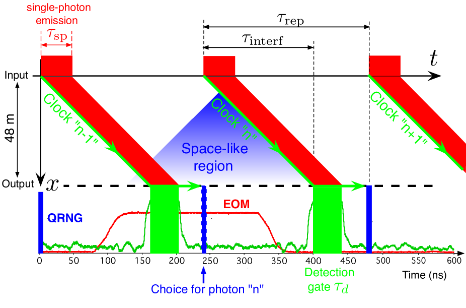
homebuilt fast driver capable to switch between and within 40 ns (?). Furthermore, the EOM switching is randomly decided, in real time, by the QRNG located close to the output of the interferometer, at 48 meters from BSinput (see Fig.2). The random number is generated by sampling the amplified shotnoise of a white light beam. As well known, shotnoise is an intrinsic quantum random process and its value at a given time cannot be predicted (?). All the experiment, from emission to detection, is synchronized by the clock that triggers the single-photon emission. In particular, in the laboratory frame of reference, the random choice between the open and closed configurations is simultaneous with the emission of the photon to which that measurement will be applied. In our geometry, it means that the photon enters the future light-cone of that random choice when it is about at the middle of the interferometer, long after passing BSinput.
The single-photon behavior is first tested using the two output detectors feeding single and coincidence counters with BSoutput removed (open configuration). We use an approach similar to the one described in References (?) and (?). We consider a run corresponding to trigger pulses applied to the emitter, with (resp. ) counts detected in path 1 of the interferometer by D1 (resp. path 2 by D2), and detected coincidences, corresponding to joint photodetections on D1 and D2 (Fig.2). Any description in which light is treated as a classical wave, like the semi-classical theory with quantized photodetectors (?), predicts that these numbers of counts should obey the inequality
| (1) |
Violation of this inequality thus gives a quantitative criterion which characterizes nonclassical behaviour. For a single-photon wavepacket, Quantum Optics predicts perfect anticorrelation i.e. in agreement with the intuitive image that a single particle cannot be detected simultaneously in the two paths of the interferometer (?). We measure showing that we are indeed close to the pure single-photon regime. The non-ideal value of the parameter is due to residual background photoluminescence of the diamond sample and to the two-phonon Raman scattering line, which both produce uncorrelated photons with Poissonian statistics.
With single-photon pulses in the open configuration, we expect each detector D1 and D2 to be unambiguously associated with a given path of the interferometer. To test this point, the “which-way” information parameter (?, ?) is evaluated by blocking one path (e.g. path 2), and measuring the counting rates at D1 and D2. A value of parameter higher than is measured, limited by detectors darkcounts and residual imperfections of the optical components. Note that the same value is obtained when the other path is blocked (e.g. path 1). In the open configuration, we have thus an almost ideal which-way measurement.
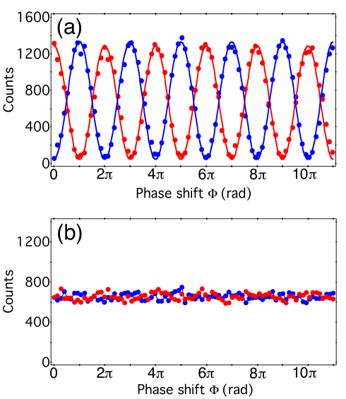
The delayed-choice experiment itself is performed with the EOM randomly switched for each photon sent in the interferometer, corresponding to a random choice between the open and closed configurations. The phase-shift between the two interferometer arms is varied by tilting the second polarization beamsplitter BS′ with a piezoelectric actuator (PZT). For each photon, we record the chosen configuration, the detection events, and the PZT position. All raw data are saved in real time and they are processed only after a run is completed. For each PZT position, detection events on D1 and D2 corresponding to each configuration are sorted. The results are shown in figure 3. In the closed configuration, we observe interference with visibility. The departure from unity is attributed to an imperfect overlap of the two interfering beams. In the open configuration interference totally disappears as evidenced by the absence of modulation in the two output ports when the phase-shift is varied. We checked that in the delayed-choice configuration, parameters and keep the same values as measured in the preliminary tests presented above.
Our realization of Wheeler’s delayed-choice GedankenExperiment demonstrates beyond any doubt that the behavior of the photon in the interferometer depends on the choice of the observable which is measured, even when that choice is made at a position and a time such that it is separated from the entrance of the photon in the interferometer by a space-like interval. In Wheeler’s words, since no signal traveling at a velocity less than that of light can connect these two events, “we have a strange inversion of the normal order of time. We, now, by moving the mirror in or out have an unavoidable effect on what we have a right to say about the already past history of that photon” (?). Once more, we find that Nature behaves in agreement with the predictions of Quantum Mechanics even in surprising situations where a tension with Relativity seems to appear (?).
Aknowledgements
We warmly thank A. Clouqueur and A. Villing for the realization of the electronics of the experiment and J.-P. Madrange for all the mechanical realization of the interferometer. We are grateful to A. Browaeys and L. Jacubowiez for their constant help and many enlighting discussions. This work is supported by Institut Universitaire de France.
References and Notes
- 1. R. P. Feynman, R. B. Leighton, and M. L. Sands, Lectures on Physics (Addison Wesley, 1963).
- 2. P. Grangier, G. Roger, and A. Aspect, Europhys. Lett. 1, 173 (1986).
- 3. F. Jelezko, A. Volkmer, I. Popa, K. K. Rebane, and J. Wrachtrup, Phys. Rev. A 67, 041802 (2003).
- 4. A. Zeilinger, G. Weihs, T. Jennewein, and M. Aspelmeyer, Nature 433, 237 (2005).
- 5. T. Aichele, U. Herzog, M. Scholtz, and O. Benson, AIP Conf. Proc. 750, 35 (2005).
- 6. V. Jacques, E. Wu, T. Toury, F. Treussart, A. Aspect, P. Grangier, and J.-F. Roch, Eur. Phys. J. D 35, 561-565 (2005).
- 7. J. A. Wheeler, pp.182-213 in Quantum Theory and Measurement, J. A. Wheeler and W. H. Zurek edit., (Princeton University Press, 1984). See in particular Fig. 4, page 183.
- 8. N. Bohr, pp.9-49 in Quantum Theory and Measurement, J. A. Wheeler and W. H. Zurek edit., (Princeton University Press, 1984).
- 9. G. Greenstein and A. G. Zajonc, The Quantum Challenge (Jones and Bartlett Publishers, 1997)
- 10. C. O. Alley, O. G. Jacubowicz, and W. C. Wickes, in Proceedings of the Second International Symposium on the Foundations of Quantum Mechanics, Tokyo (1986), H. Narani ed. (Physics Society of Japan, 1987).
- 11. T. Hellmut, H. Walther, A. G. Zajonc, and W. Schleich, Phys. Rev. A 72, 2533 (1987).
- 12. J. Baldzuhn, E. Mohler, and W. Martienssen, Z. Phys. B 77, 347 (1989).
- 13. B. J. Lawson Daku, R. Asimov, O. Gorceix, C. Miniatura, J. Robert, and J. Baudon, Phys. Rev. A 54, 5042 (1996).
- 14. Y.-H. Kim, R. Yu, S. P. Kulik, Y. Shih, and M. O. Scully, Phys. Rev. Lett. 84, 001 (2000).
- 15. T. Kawai, T. Ebisawa, S. Tasaki, M. Hino, D. Yamazaki, T. Akiyoshi, Y. Matsumoto, N. Achiwa, Y. Otake, Nucl. Inst. Meth. A 410, 259 (1998).
- 16. See e.g. Focus on Single Photons on Demand, New J. Phys. 6 (2004).
- 17. A. Beveratos, R. Brouri, T. Gacoin, A. Villing, J.-P. Poizat, and P. Grangier, Phys. Rev. Lett. 82, 187901 (2002).
- 18. R. Alléaume, F. Treussart, G. Messin, Y. Dumeige, J.-F. Roch, A. Beveratos, R. Brouri-Tualle, J.-P. Poizat, and P. Grangier, New J. Phys. 6, 92 (2004).
- 19. A. Beveratos, S. Kuhn, R. Brouri, T. Gacoin, J.-P. Poizat, and P. Grangier, Eur. Phys. J. D 18, 191 (2002).
- 20. A. Gruber, A. Dräbenstedt, C. Tietz, L. Fleury, J. Wrachtrup, and C. von Borczyskowski, Science 276, 2012 (1997).
- 21. C. Kurtsiefer, S. Mayer, P. Zarda, and H. Weinfurter, Phys. Rev. Lett. 85, 290 (2000).
- 22. R. Brouri, A. Beveratos, J.-P. Poizat, and P. Grangier, Opt. Lett. 25, 1294 (2000).
- 23. H.-A. Bachor and T. C. Ralph, A Guide to Experiments in Quantum Optics (Wiley-VCH, 2004).
- 24. W. E. Lamb and M. O. Scully, in “polarization, Matière et Rayonnement”, volume in honour of A. Kastler, (Presses Universitaires de France, 1969).
- 25. P. Grangier, Thèse d’état (1986), Institut d’Optique et Université Paris 11; available online at http://tel.ccsd.cnrs.fr/tel-00009436
- 26. B.-G. Englert, Phys. Rev. Lett. 77, 2154 (1996).
- 27. N. Gisin, quant-ph/0512168.
Figures
Methods
Triggered single-photon source
We use a single nitrogen-vacancy (N-V) color center in a diamond nanocrystal. The N-V centers are created by irradiation of type Ib diamond sample with high-energy electrons followed by annealing at °C111C. Kurtsiefer, S. Mayer, P. Zarda, and H. Weinfurter, Phys. Rev. Lett. 85, 290 (2000).. Under a well controlled irradiation dose, the N-V center density is small enough to allow independent addressing of a single center using standard confocal microscopy222A. Gruber, A. Dräbenstedt, C. Tietz, L. Fleury, J. Wrachtrup, and C. von Borczyskowski, Science 276, 2012 (1997). The experimental setup used to excite and spectrally characterize single color center photoluminescence is depicted on Fig. 4.
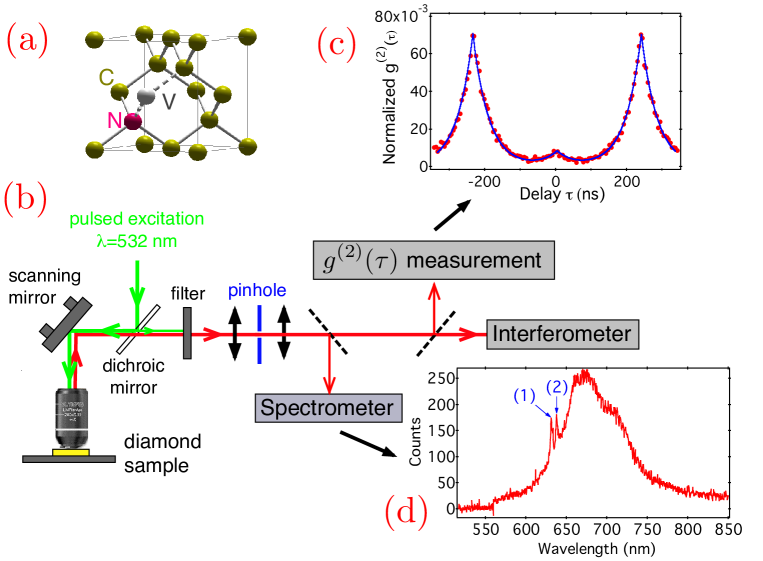
Excitation is done with a home-built pulsed laser at a wavelength of 532 nm 333A. Beveratos, S. Kuhn, R. Brouri, T. Gacoin, J.-P. Poizat, and P. Grangier, Eur. Phys. J. D 18, 191 (2002).. The laser system delivers 800 ps pulses with energy 50 pJ, high enough to ensure efficient pumping of the color center in its excited level. The repetition rate, synchronized on a stable external clock, is set at MHz so that successive fluorescent decays are well separated in time from each other. Single photons are thus emitted by the N-V color center at predetermined times within the accuracy of its excited state lifetime, which is about 45 ns for the center used in the experiment (see Fig.4-(c)).
Significant limitation of defect photoluminescence in diamond arises from the high index of refraction of the bulk material (), which makes an efficient extraction of the emitted photons difficult. Refraction at the sample interface leads to a small collection efficiency, limited by total internal reflection and strong optical aberrations. An efficient way to circumvent these problems is to consider the emission of defects in diamond nanocrystals, with size much smaller than the wavelength of the radiated light 444A. Beveratos, R. Brouri, T. Gacoin, J.-P. Poizat, and P. Grangier, Phys. Rev. A 64, 061802R (2001).. The sub-wavelength size of the nanocrystals renders refraction irrelevant and one can then simply treat the color center as a point source radiating in air. Furthermore, the small volume of diamond excited by the pumping laser yields very low background light. Such property is of crucial importance for single-photon emission, since residual background light will contribute to a non-vanishing probability of having more than one photon within the emitted light pulse.
Nanostructured samples are prepared by starting with type Ib synthetic
diamond powder (ElementSix, The Netherlands) 3,4. After
irradiation, diamond nanocrystals are dispersed into a polymer solution
and then size-selected by centrifugation, with a mean
diameter of about 90 nm. The resulting polymer solution containing
selected diamond nanocrystals is spin-coated onto the surface
of a dielectric mirror, yielding a 30-nm-thick polymer layer which
subsequently holds the diamond nanocrystals. The ultra-low
fluorescing dielectric structure of the mirror (Layertec, Germany) is
optimized to efficiently reflect the photoluminescence of the
N-V color center towards the collection optics. We note that the background fluorescence from the mirror
dielectric layers is strongly reduced due to photobleaching after a few hours of sample illumination, while the N-V color center emission properties remain unaffected.
Single-photon interferometer with two spatially separated paths
The experiment is based on a 48-meter-long interferometer depicted in the article, very close to the Mach-Zehnder interferometer configuration. A linearly polarized single-photon pulse is sent through a first YVO4 polarization beamsplitter (BSinput) with oriented polarization eigenstates. The two S and P linear polarizations at the output of BSinput are then spatially separated by 4 mm, sufficient to avoid any overlap between the two beams, since each beam size is about 1 mm. To limit diffraction effects due to open-air propagation along the interferometer, two afocal systems with magnification are used. After m propagation, equivalent to a time of flight of , a second polarization beamsplitter (BS′) overlaps the two spatially separated polarizations without recombining the two orthogonally polarized paths of the interferometer. At the output of BS′, the two overlapping polarized channels are sent through a KDP electro-optical modulator (EOM, Linos LM0202, Germany) and a Wollaston prism which separates S and P polarizations. Finally, two silicon avalanche photodiodes (APD) operating in the photon counting regime (Perkin Elmer AQR) are positioned at the output ports. Depending on the voltage appplied to the EOM ( or ), the interferometer is either closed or open as depicted in Fig.5.
At last, the N-V center photoluminescence is spectrally filtered with a 10 nm FWHM bandwidth centered at 670 nm to avoid any problem of chromatism of the afocal systems and any reduction of interference visibility due to the broadband emission of the N-V color center (see Fig.4-(d)). Finally counting rates of about are measured on each detector in the open configuration. The corresponding signal to noise ratio of about 10 is essentially limited by darkcounts of the two APDs, on the order of for each.
Quantum Random Number Generator
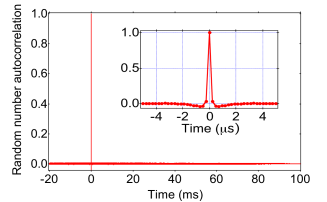
To ensure space-like separation between the entrance of the photon into the interferometer and the choice of the performed measurement, the applied voltage on the EOM is randomly chosen in real time, using a Quantum Random Number Generator (QRNG) located at the output of the interferometer. The random numbers are generated from the amplified shotnoise of a white lightbeam. For each clock pulse, i.e. every ns, fast comparison of the amplified shotnoise to the zero level generates a binary random number or . As shown on Fig. 6, the autocorrelation function of a random number sequence reveals no significant correlations between different drafts over the time scale relevant for the experiment. We also checked by direct sampling of the amplified shotnoise every 10 ns that its correlation time is approximatively 60 ns. This measurement confirms that choices made at the MHz clock rate are uncorrelated.
Timing of the experiment
A small fraction of the pump pulsed laser at 532 nm is used to clock-trigger the experiment with 4.2 MHz repetition rate, corresponding to an excitation of the color center every 555Since the time of flight of the photon in the interferometer is smaller than the excitation period , only one single-photon pulse is inside the interferometer at a time.. As depicted on Fig.7, an FPGA programmable circuit generates for each clock pulse the following sequence. First, fast comparison of the amplified shotnoise to the zero level generates a binary random number 0 or 1 which drives the voltage applied to the EOM, switching between the open and closed configurations. Then a detection gate of duration is adjusted with appropriate time delays to coincide with the photon arrival on detectors D1 and D2 666This gated detection leads to a significant decrease of the effective number of dark counts of D1 and D2.. The FPGA electronics is programmed in order that the random number generation is realized 160 ns before the detection gate, which corresponds to the time of flight of the photon inside the interferometer. The QRNG is then drawn simultaneously with the photon emission, within the accuracy of the excited level lifetime of the N-V center (see Fig.4-(b)).
As shown in the space-time diagram of Fig.7, if the single-photon appears at the very beginning (resp. at the very end) of its time-emission window, it has been inside the interferometer for 85 ns (resp. 40 ns), meaning 25 m (resp.12 m) away from the input beamsplitter, when the EOM voltage starts to commute. Furthermore, such timing ensures that the two events “entering of the photon into the interferometer at BSinput” and “choice of the experimental configuration at BSoutput” are space-like separated in a special relativistic sense, as required in Wheeler’s proposal. Indeed, the photon enters the future light-cone of the random choice when it is about at the middle of the interferometer, long after passing BSinput.