Quantum computers based on electron spins controlled by ultra-fast, off-resonant, single optical pulses
Abstract
We describe a fast quantum computer based on optically controlled electron spins in charged quantum dots that are coupled to microcavities. This scheme uses broad-band optical pulses to rotate electron spins and provide the clock signal to the system. Non-local two-qubit gates are performed by phase shifts induced by electron spins on laser pulses propagating along a shared waveguide. Numerical simulations of this scheme demonstrate high-fidelity single-qubit and two-qubit gates with operation times comparable to the inverse Zeeman frequency.
pacs:
03.67.Lx, 32.80.Qk, 33.35.+r, 42.65.ReQuantum computers potentially allow improvement in computational speed over existing computers if an architecture is found with a fast clock rate and the ability to be scaled to many qubits and operations Nielsen and Chuang (2000). Electron spins of charged semiconductor quantum dots are promising candidates for such an architecture because of their potential integration into existing micro-technology. Most proposals for electron spin quantum computers Loss and DiVincenzo (1998); Vrijen et al. (2000); Childress et al. (2006); Petta et al. (2005), however, restrict logic operations to nearest-neighbors, limiting the computational clock rate. Optically mediated quantum logic Imamoglu et al. (1999); Piermarocchi et al. (2002); Spiller et al. (2006); Yao et al. (2005) for two-qubit gates and fast single qubit rotations Economou et al. (2006); Dutt et al. (2006) may improve the overall clock rate of the system.
Several previous works suggest techniques for fast single-qubit rotations of electron spins. Ground-state coherence generation via ultrafast pulses in molecular, atomic, and quantum dot spectroscopy Suter and Mlynek (1991); Kis and Renzoni (2002); Meshulach and Silberberg (1998); Dudovich et al. (2002); Wu et al. (2004); Dutt et al. (2006) indicates the ability to control ground state populations and phases. This control is faster than that of microwave pulses or multiple, adiabatic narrow-band optical pulses. The application of ultrafast pulses to U(1) control of single quantum-dot qubits has been proposed Economou et al. (2006). Here we describe complete optical SU(2) control of single dots using similar techniques.
There are also proposals for optically-mediated entanglement formation between two non-local qubits. One type of proposal uses coherently generated single photons Yao et al. (2005); Cirac et al. (1997), but requires precisely shaped optical pulses. Recent methods for the entanglement of atomic ensembles via simple optical pulses Lukin et al. (2000); Duan et al. (2000) have led to proposals for optically-mediated two-qubit gates based on small phase shifts of light via single qubits in cavities Spiller et al. (2006). These latter techniques may be easier and faster than the use of coherently generated single photons. Here, we propose a unique way to combine both fast, SU(2) single-qubit rotations and fast, optically-mediated two-qubit gates on a single semiconductor chip. These elements may lead toward the fastest potentially-scalable quantum computing scheme of which the authors are aware.
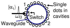
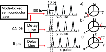
Figure 1 shows a key component of such an architecture. It is a square millimeter of a semiconductor chip patterned with cavities. Each cavity holds a single charged quantum dot and is connected to other cavities through a switched, circular waveguide. Each quantum dot can be individually addressed by focused optical pulses incident perpendicular to the plane of the chip to perform single qubit rotations. These pulses are part of a pulse train that serves as the system clock and could be supplied by a semiconductor mode-locked laser Sato (2001). Pulses in the plane of the chip couple distant qubits, forming a “quantum bus” or “qubus,” which is the foundation of a two qubit gate.
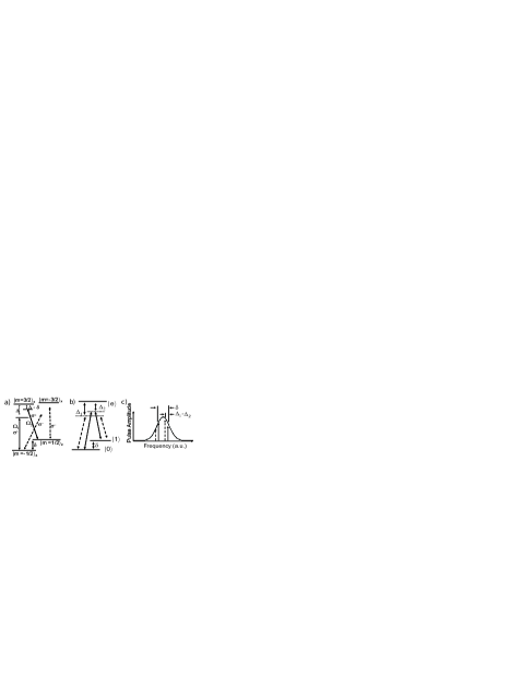
We now examine each aspect of this scheme in more detail. The dots themselves are single-charged, large-area quantum dots (e.g. InGaAs). Such dots are strong candidates for this architecture because they readily form the three-level system necessary for stimulated Raman transitions (Fig. 2a) and they have the large oscillator strengths Gammon et al. (1996) necessary for fast spin rotations. The two lower states of this system are the electron Zeeman states and are split by a magnetic field applied along the -direction, which is perpendicular to the growth axis. The excited state consists of two electrons in a spin-singlet and a hole. The large heavy-hole/light-hole splitting allows us to neglect states from the light-hole excitons and describe the exciton angular-momentum states in the -basis: . If we apply -polarized light to the system, the two electron-spin states, denoted and , are coupled to each other through the single state, denoted (Fig. 2a and b).
Both single qubit and two-qubit gates can be understood from the rotating-frame Hamiltonian
| (1) |
where is the projection operator for and is the raising operator for . Referring to Fig. 1, is the ground-state splitting and is the detuning of the center frequency of the light pulse from , the frequency of the transition. The meaning of the Rabi frequency differs in the analyses of single and two-qubit gates. For single qubit gates, the intense light pulse perpendicular to the cavity is treated as a classical field and is the product of the dipole matrix element and the time-dependent electric field amplitude of the the light. For two-qubit gates, a weak coherent state of light interacts with the quantum dot in the single-mode cavity and is a time-dependent Jaynes-Cummings coupling parameter multiplied by the cavity-photon annihilation operator . There are also incoherent dynamics to be included in the time evolution of the system, so that the total time evolution is governed by the master equation
| (2) |
Here, is the spontaneous emission rate of state and is the electron spin decoherence rate.
An approximation of the solutions of this equation may be found by the adiabatic elimination of the excited state, which is valid when the detuning is much larger than all other rates in the system. The three-level system is then reduced to the two-level spin system with effective Hamiltonian where is the spin operator of the electron, generates an irrelevant overall phase, and the effective field is approximately
| (3) | ||||
| (4) |
For simplicity, we consider a symmetric system with , in which case . Small deviations from this condition may alter the direction of during the pulse, but they do not adversely affect the overall scheme.
For single-spin rotations in which short, intense, highly detuned pulses are used, the effective field can be much larger than the applied magnetic field; i.e. the effective Rabi frequency is much faster than the Larmor frequency. The rotation axis is determined by the phase difference between frequency components that are separated by the Zeeman frequency within the pulse spectrum (Fig. 2b and c) and thus by the delay time of the pulse with respect to clock intervals occurring with period . To see this, imagine that the spin precesses at Larmor frequency for a time , at which point an intense, broadband pulse is applied that rotates it through an angle about , which is approximately in the direction. Then, the spin freely precesses again for a time . This sequence can be written as the unitary operator
| (5) |
which describes a rotation with an axis determined by . Pulses in a pulse train starting at that arrive at intervals of exactly one Larmor period cause rotations around the same axis, which we define as the -axis. Pulses delayed by one fourth or one half of the clock period will have a phase difference of or , causing rotations about the -axis or -axis, respectively (Fig. 3). This sequence of three pulses can occur in less than the inverse Zeeman frequency, and thus for a reasonable Zeeman splitting of 100 GHz, an arbitrary single qubit gate can be implemented in 10 ps.
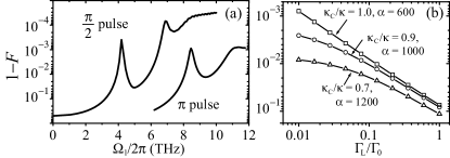
To evaluate the importance of terms neglected in our approximate analysis, we numerically solve Eq. (2) as a three-state system driven by the classical field using adaptive Runge-Kutte techniques. We use the realistic quantum dot parameters ps Hours et al. (2005), s Petta et al. (2005); Greilich et al. (2006), and GHz. We assume a Fourier-transform-limited Gaussian pulse detuned by 10 THz with 100 fs full-width-half-maximum. Using the definition of fidelity , where is the desired quantum state, we find it is possible to implement both - and -pulses with a fidelity (applied pulse energy densities of 14 J/cm2 and 5 J/cm2 respectively, which is within the energy output of mode-locked semiconductor lasers followed by optical amplifiers). The fidelity as a function of Rabi frequency (at the optimal detuning) is shown for both - and pulses in Fig. 4a. The general shape of the curve is increasing with Rabi frequency, as larger Rabi frequencies allow for larger detunings and therefore excite less population into the excited state. There are also some oscillations visible in the curve that are related to Rabi oscillations as the system finds optimum detuning regions. The high fidelity of the single-pulse Raman rotation is due to the speed of the pulse; all relaxation and decoherence processes occur at a time scale much slower than the pulse time.
For two-qubit gates implemented via the “qubus” concept, the single mode cavity is driven by a narrow-band coherent-state pulse. We assume , where is the coherent state amplitude and is the vacuum Rabi splitting of the microcavity system. With this assumption, the Hamiltonian is nearly diagonal and there is negligible population change to the qubit. According to perturbation theory, the dominant correction term is the first-order diagonal correction found in the rightmost term of Eq. (3). This term describes an effective Hamiltonian of the form , with . This interaction varies the phase of the coherent state field depending on the spin-state of the quantum dot. Quantum logic is implemented by interspersing these optical phase shifts with optical displacements achieved by mixing the coherent state pulse with a reference pulse at the optical switch. Assuming fast, accurate control of the switching ratio as well as the timing and phase of the reference pulses, the amplitude of the coherent state may be taken through a closed path in phase space. The area of this path, and the resulting geometric phase, depends on the states of the two qubits interacting with the field, allowing a controlled-phase gate. Such a gate is deterministic and does not require detection or feedback. For details, see Ref. Spiller et al., 2006.
The magnitude of the conditional phase shift depends on the detuning and the coherent state amplitude . If is too small compared to , there is insufficient selectivity between the two levels. If is too large, the magnitude of becomes too small compared to decoherence processes. Increasing increases the phase shift, but if is too large then decoherence due to spontaneous emission and cavity losses becomes stronger.
To verify the magnitude and fidelity of the phase-shift operation as a function of and , we performed simulations of the interaction described by Eq. (2). Although the fully-connected system employed in this paper is different from the asymmetric system considered in Ref. Ladd et al., 2006, the effective Hamiltonian is the same, and thus many of the qualitative conclusions apply. Unlike Ref. Ladd et al., 2006, however, quantitative calculations for the present proposal require a fully-quantum-mechanical description of the cavity field, because the previous semi-classical approach fails when pulses are too fast. For our simulations, we use a basis of displaced Fock states, , where If a conditional phase shift occurs, the quantum dynamics may be simulated by a space of approximately of these states ( for qubus logic). We use more states than needed in the calculation to assure numerical accuracy. For these calculations, where is the convolution of the input pulse shape with the filter function of the cavity Ladd et al. (2006). Spontaneous emission in the cavity mode may leak into both the waveguide, with rate , and to lossy modes or absorption, with rate . The decay rate is now taken as the rate of spontaneous emission into non-cavity modes, , plus emission into the cavity mode that is lost, so , where is the decay rate of the dot in the absence of the cavity (taken to be (200 ps)-1), and is the Purcell factor at high detuning. For our simulations, we assume a modest cavity of 1000 and a cavity mode-volume of one cubic wavelength inside the semiconductor; typical parameters for semiconductor microcavities Englund et al. (2005).
The simulations start with the system in the superposition state , where is the initial state of the coherent-state optical pulse. The fidelity is then calculated as the overlap of the final density matrix with some pure state , where are different optical states. We find that Gaussian pulses with root-mean-square width much shorter than 20 ps cause these optical states to vary significantly from the desired phase-shifted coherent states. However, for 20 ps pulses and with detunings of THz, we are able to find values of large enough to assure coherent states shifted by . We find that the final-state fidelity depends on the cavity figures-of-merit and , as shown in Fig. 4b. If , a value consistent with existing photonic crystal cavities Englund et al. (2005), the fidelity may reach 99.3%. The fidelity may also be improved by increasing the pulse length, increasing the , or decreasing the mode-volume of the cavity. Lastly, the fidelity of the final gate also depends on optical loss in the waveguide. The analysis in Ref. Ladd et al., 2006 indicates that the percent reduction of gate fidelity is about equal to the percent amount of loss, and will therefore be a critical parameter to optimize when designing a fault-tolerant architecture.
The time required for two-qubit gate operations is limited by the pulse width and the pulse propagation time between the two qubits. Nonlocal two-qubit gates will therefore take just a few periods of the 100 GHz system clock. To allow gates between arbitrary qubits, qubits must be switched “on” and “off” with respect to their coupling to the probe pulse field. In the schematic of Fig. 1, it is supposed that each cavity is far off-resonant from the probe pulse field so that the qubit is “off” with respect to light-mediated two-qubit gates. To switch the interaction on for a particular dot, a powerful, focused, mid-band light source is introduced only at the cavity of interest to instantaneously tune it to resonance with the probe pulse (but still detuned by from the dot) via the optical Kerr nonlinearity.
Several features of this scheme favor scalability. The ability to achieve two qubit gates between arbitrarily distant qubits is a key advantage, since schemes relying on nearest-neighbor interactions have more difficulty achieving fault-tolerant operation Svore et al. (2005). Another advantage of our approach is that the two quantum dots participating in two-qubit gates need not have the same frequency; several THz inhomogeneity is tolerated, easing the possibility of large-scale fabrication. Multiple rings of qubits could be integrated on a single chip and operated in parallel. Fast measurement of the qubits could be accomplished by the same conditional-phase shifts of bright coherent pulses that are measured via homodyne detection with ordinary photodetectors.
One technical challenge is presented by the -factor inhomogeneity of quantum dots. This inhomogeneity necessitates the use of spin-echo techniques to synchronize each qubit with the master clock. This technical burden may be relieved by using donor-bound excitons instead, as these impurity transitions form the needed transition but show improved homogeneity Karasyuk et al. (1994); Fu et al. (2005).
In summary, we have outlined a proposal for performing ultra-fast, optically controlled quantum gates on electron spins in quantum dots using stimulated Raman scattering and qubit-controlled phase shifts with single optical pulses. For the single-qubit rotations, the optical pulses have a bandwidth large compared to the splitting of the two lower states; for two-qubit gates the pulses must have a narrower bandwidth, but may still be as short as 20 ps. The timing of the optical pulses is precisely controlled to provide the system’s clock signal and control the qubit rotation axis. The clock speed of a single qubit gate in this scheme is limited only by the lower state splitting. These methods provide the basis for an ultra-fast, scalable, solid-state, electron spin based, all-optical quantum computer.
The authors thank H. Wang, S. E. Harris, K. Nemoto, W. Munro, and D. Press for helpful discussions. S. Clark was partially supported by the HP Fellowship Program through the Center for Integrated Systems. This work was financially supported by the MURI Center for photonic quantum information systems (ARO/ARDA Program DAAD19-03-1-0199), JST/SORST program for the research of quantum information systems for which light is used, “IT program” MEXT, University of Tokyo, and the “Qubus quantum computer program” MEXT, NII.
References
- Nielsen and Chuang (2000) M. A. Nielsen and I. L. Chuang, Quantum Computation and Quantum Information (Cambridge University Press, New York, 2000).
- Loss and DiVincenzo (1998) D. Loss and D. P. DiVincenzo, Phys. Rev. A 57, 120 (1998).
- Vrijen et al. (2000) R. Vrijen et al., Phys. Rev. A 62, 012306 (2000).
- Childress et al. (2006) L. Childress et al., Phys. Rev. Lett. 96, 070504 (2006).
- Petta et al. (2005) J. R. Petta et al., Science 309, 2180 (2005).
- Imamoglu et al. (1999) A. Imamoglu et al., Phys. Rev. Lett. 83, 4204 (1999).
- Piermarocchi et al. (2002) C. Piermarocchi et al., Phys. Rev. Lett. 89, 167402 (2002).
- Spiller et al. (2006) T. P. Spiller et al., New J. Phys. 8, 30 (2006).
- Yao et al. (2005) W. Yao, R.-B. Liu, and L. J. Sham, Phys. Rev. Lett. 95, 030504 (2005).
- Economou et al. (2006) S. E. Economou et al., Phys. Rev. B 74, 205415 (2006).
- Dutt et al. (2006) M. V. G. Dutt et al., Phys. Rev. B 74, 125306 (2006).
- Suter and Mlynek (1991) D. Suter and J. Mlynek, Phys. Rev. A 43, 6124 (1991).
- Kis and Renzoni (2002) Z. Kis and F. Renzoni, Phys. Rev. A 65, 032318 (2002).
- Meshulach and Silberberg (1998) D. Meshulach and Y. Silberberg, Nature 396, 239 (1998).
- Dudovich et al. (2002) N. Dudovich, D. Oron, and Y. Silberberg, Nature 418, 512 (2002).
- Wu et al. (2004) Y. Wu et al., Physica E 25, 242 (2004).
- Cirac et al. (1997) J. I. Cirac et al., Phys. Rev. Lett. 78, 3221 (1997).
- Lukin et al. (2000) M. D. Lukin, S. F. Yelin, and M. Fleischhauer, Phys. Rev. Lett. 84, 4232 (2000).
- Duan et al. (2000) L.-M. Duan et al., Phys. Rev. Lett. 85, 5643 (2000).
- Sato (2001) K. Sato, Electronic Letters 37, 763 (2001).
- Gammon et al. (1996) D. Gammon et al., Science 273, 87 (1996).
- Hours et al. (2005) J. Hours et al., in Physics of Semiconductors: International Conference on the Physics of Semiconductors (2005), p. 771.
- Greilich et al. (2006) A. Greilich et al., Science 313, 341 (2006).
- Ladd et al. (2006) T. D. Ladd et al., New J. Phys. 8, 184 (2006).
- Englund et al. (2005) D. Englund et al., Phys. Rev. Lett. 95, 013904 (2005).
- Svore et al. (2005) K. M. Svore, B. M. Terhal, and D. P. DiVincenzo, Phys. Rev. A 72, 022317 (2005).
- Karasyuk et al. (1994) V. A. Karasyuk et al., Phys. Rev. B 49, 16381 (1994).
- Fu et al. (2005) K.-M. C. Fu et al., Phys. Rev. Lett. 95, 187405 (2005).