ALTERNATE SCHEME FOR OPTICAL CLUSTER-STATE GENERATION WITHOUT NUMBER-RESOLVING PHOTON DETECTORS
Abstract
We design a controlled-phase gate for linear optical quantum computing by using photodetectors that cannot resolve photon number. An intrinsic error-correction circuit corrects errors introduced by the detectors. Our controlled-phase gate has a 1/4 success probability. Recent development in cluster-state quantum computing has shown that a two-qubit gate with non-zero success probability can build an arbitrarily large cluster state with only polynomial overhead. Hence, it is possible to generate optical cluster states without number-resolving detectors and with polynomial overhead.
keywords:
cluster states, linear optical quantum computing1 Introduction
The protocol of one-way quantum computing opened a new paradigm in quantum computation. Single-qubit measurements on a set of highly entangled qubits—the so called cluster state[1]—perform the computation in one-way quantum computing. On the other hand, in the usual quantum-circuit approach, Knill, Laflamme, and Milburn (KLM) utilized the idea of gate teleportation[2] for scalable optical quantum computing. KLM introduced a non-deterministic two-qubit controlled-phase gate that succeeds with probability arbitrarily close to one, given a sufficiently large ancilla state[3]. Nielsen later applied the KLM method to one-way quantum computing in the effort to decrease the number of required physical resources[4]. “Qubit fusion”[5] and “quantum parity check” operations[6] have improved the scalability of linear optical quantum computation (see Ref. \refcitekok:135 for a review). Two recent experiments have implemented the one-way quantum computing model with photonics[8, 9].
Many researchers consider the number-resolving-detector requirement as inevitable for either the one-way or quantum circuit approach for linear optical quantum computing. The number-resolving capability is an essential requirement in a quantum repeater protocol for long distance communication[10]. Browne and Rudolph showed that number-resolving detectors are not necessary for building optical cluster states by using redundant encoding in Type-II fusion[5]. We address the necessity of number-resolving photon detectors for the implementation of linear optical quantum computing. We provide an alternate scheme for building cluster states using an optical controlled-phase gate that does not rely on number-resolving detectors. We note that some authors recently presented another scheme for building cluster states without number-resolving detectors[11].
We utilize the KLM-type ancilla state of four qubits with a source of pure polarization-entangled Bell states. We adopt a polarization-encoding scheme[12]. It has the advantage of immunity to photon loss errors[13]. Our scheme requires a source of high-fidelity polarization-entangled Bell states[14]. The controlled-phase gate succeeds with probability with the aid of a four-qubit ancilla state. Intriguingly, previous researchers have suggested using a probabilistic two-qubit gate with non-zero success probability to build an arbitrarily large cluster state[15, 16]. Preparation of two-dimensional cluster states requires only polynomial overhead[17, 18]. Our controlled-phase gate scheme removes the necessity of number-resolving detectors for building an arbitrarily large optical cluster state.
Figure 1 outlines our controlled-phase-gate design.
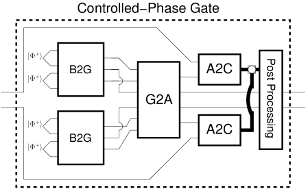
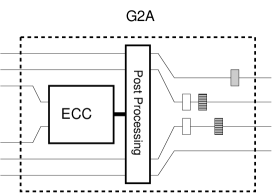
B2G (Bell-to-GHZ) converts Bell states to GHZ states with success probability. G2A (GHZ-to-four-qubit-Ancilla) corrects for possible errors introduced in B2G. G2A converts pure GHZ states to the following four-qubit ancilla state [2, 3, 12]:
| (1) |
The conversion probability is given two pure GHZ states. A2C (four-qubit-Ancilla-to-Controlled-phase) uses to perform a controlled-phase gate with success probability. The gate heralds success using photon detectors that do not resolve photon number.
 (a)
(a)
|
 (b)
(b)
|
 (c)
(c)
|
 (d)
(d)
|
2 Polarization-Independent Detectors
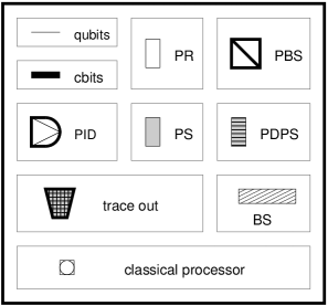
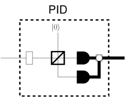
Polarization-independent detectors (PIDs) detect the number of photons in a spatial mode independent of their polarization (Figure 2(c)). Two ordinary photon detectors follow the polarization rotator (PR) and the polarizing beam splitters (PBS). The classical processor processes the result of the two detectors’ photon number measurement. It sends classical control signals to optical elements that perform conditional post-processing on the remaining computational modes. We illustrate its operation on the computational basis of one incoming spatial mode:
| (2) | |||||
| (3) |
The outcome of the photon number measurement in each case is either or with probability . The detectors only gain information about the photon number in the incoming spatial mode—they learn nothing about polarization.
We illustrate a useful feature of a PID. Suppose we have a polarization-entangled state
| (4) |
We can measure the photon number of the last mode of using a PID and obtain the state . This retaining of entanglement is not possible with a typical photon number measurement.
A PID processing ’s last mode gives the state:
| (5) |
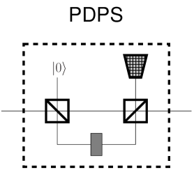
The state after measurement is the polarization-entangled state if we measure and state if we measure . The classical processor in the PID in Figure 2(c) obtains the result of the measurement and forwards it to a set of post-processing linear optical elements. Post-processing is as follows: do nothing for measurement result , or evolve state to for measurement result . Evolve by performing a PDPS of on exactly one mode of . So we possess as a resource for subsequent computations. We exploit this feature in B2G.
3 Preparation of a GHZ state from two Bell states
Suppose we have a source of pure Bell states
| (6) |
Note the following conventions:
| (7) | |||||
| (8) |
B2G in Figure 2(d) converts pure Bell states to a mixture of and . B2G is nothing but the quantum parity check[6] and similar to Type I fusion[5]. A mixture results because the photon detectors are not number resolving. We use polarization-independent detectors in our scheme where the scheme in Ref. \refciteprl2005browne uses detectors dependent on the polarization of the incoming photons.
B2G begins by feeding in two Bell states at the four input ports in Figure 2(d). propagates after the PBS as follows (with the third mode rearranged as the last mode):
| (9) |
We perform a PID on the last mode. The quantum state becomes the following before the detectors in the PID:
| (10) |
denotes two horizontally polarized photons in a given path. The detectors in the PID measure the last two modes and cannot distinguish between and or and because they cannot resolve photon number. Thus and refer to the same measurement result so we name them and where is an arbitrary positive integer. Post-processing on the quantum state in (10) is as follows: discard and start over if we measure , perform a PDPS of on the first mode if we measure , or do nothing if we measure .
The state becomes the mixture (the partial GHZ mixture) after the above conditioning.
| (11) |
We obtain a pure GHZ state with probability after performing B2G on two pure Bell states.
 (a)
(a)
|
 (b)
(b)
|
4 Preparation of the four-qubit ancilla state from two GHZ states
G2A in Figure 3(a) converts the output of two parallel runs of B2G to the four-qubit ancilla state . G2A performs this conversion with a success probability of when pure GHZ states are input. We perform this conversion using photon detectors which are not number resolving. We have a procedure that corrects for the error introduced into the mixed state in (11). This conversion only has a non-unit probability of success, but we know whether the conversion fails or succeeds. Two parallel runs of B2G generate two copies of . We input four Bell states to the two B2Gs.
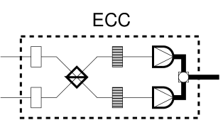
4.1 Intrinsic Error Correction Circuit
The second mode of may have an error. So we send the second mode of each copy of through the ECC (Error Correction Circuit) depicted in Figure 3(b). ECC is the first part of G2A. ECC is similar to Type II fusion[5]. We use it for two purposes. It detects whether two pure GHZ states are actually input to G2A. ECC then produces a state which deterministically converts to the four-qubit ancilla state . It only produces the convertible state if two pure GHZ states are at the input of G2A. G2A is similar to a Type-II fusion gate, which (in the language of Ref. \refciteprl2005browne) creates a “redundantly-encoded” two-qubit cluster state (across four photons) and simultaneously filters out the unwanted two-photon parts of the wavefunction of the input states (as described by Ralph et al. in Ref. \refciteprl2005ralph).
Suppose that the state is input to G2A. We can detect this state uniquely by noting that no one of the four detectors in the two PIDs fire. We discard and start over if we detect zero photons.
Suppose that either the state or is input to ECC. The left column of Table 4.1 gives possible states of the two middle modes in either of the two superpositions: or . Table 4.1 aids in determining the resulting state before the detector measurement. Each measurement result has zero photons in exactly three of the four modes. We discard and start over if we detect zero photons in exactly three modes.
The left column contains possible initial states of the two middle modes of state or state . The right column contains resulting states after ECC processes initial states. The two PIDs transform the two modes in the initial states to four modes (see Figure 2(b)). Init. Resulting States
Suppose that two pure GHZ states are input to ECC. The left column of Table 4.1 gives possible states of the two middle modes in the superposition just before the detectors in the two PIDs.
The left column contains the possible initial states of the two middle modes of . The right column contains the resulting states after the ECC operation processes the initial states and just before detection. We employ the following shorthand notation: , , , , , , , , , . All resulting states require normalization. Init. Resulting States
We determine a method to correct for the error introduced in B2G by analyzing Table 4.1. We discard the computation if we measure zero photons in exactly three modes—the resulting states are in Table 4.1, as well as all the resulting states given in Table 4.1. We only need detectors that distinguish between no photons and some photons. Keep the state if zero photons are in only two modes. We thus determine with certainty whether two pure GHZ states are input to G2A.
We analyze the result of ECC only when two pure GHZ states are input to G2A. Reorder the state so that the middle two modes become the last two modes: . Table 4.1 entries give the resulting state after ECC.
ECC (Figure 3(b)) works only if the original Bell states are pure. If the original Bell states have timing jitters, a PBS can purify them. If, on the other hand, the Bell-state source has the possibility of emitting a four-photon pair, the purification is seemingly not possible. Therefore, our scheme doesn’t not work if we use spontaneous parametric down conversion as our source of the Bell pairs. It is possible to implement the desired ECC if we use the source without multiple-pair emission such as the recently developed semiconductor source[14].
The left column contains measurement results when passing the two middle modes of through ECC. The right column contains the resulting states of the four other modes which do not pass through ECC. Meas. Resulting States
The left column contains the measurement results after two A2Cs. The right column contains post-processing for the two remaining computational modes given the measurement result (using the shorthand in Table 4.1). Meas. Post-processing Operations PR on both modes, PDPS of on mode 2 Same as above with a PS of PR on mode 2, PS, PDPS of on mode 2 Same as above with a PS of PDPS of on mode 2 Same as above with a PS of PR on mode 1, PS, PDPS of on mode 2 Same as above with a PS of
4.2 Feed-forward to the four-qubit ancilla state
We perform the following post-processing conditioning on the state resulting from ECC: perform a PDPS by on modes two and three if we measure either or , or perform a PS by if we measure either or . The resulting (unnormalized) state is as follows: . The later elements of G2A convert the above state deterministically to (up to a global phase of ) with a PR by on modes two and three, a PDPS of on mode two, a PDPS of on mode three.
5 Probabilistic Controlled-Phase Gate
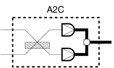
The controlled-phase takes each computational basis state to itself except becomes . Suppose the four computational basis elements are inputs in Figure 1. Suppose the first part of the controlled-phase generates (occurring with probability ). We determine the propagation of the following four states through the latter half of the controlled-phase: , , , . The modes in Figure 1 are in increasing order from top to bottom. We determine the state of modes three and four after the two A2Cs by first analyzing A2C acting on , , , and . All four combinations occur when the two A2Cs act on modes 1, 2, 5, and 6 of the above six-mode states.
A2C consists of a beam splitter followed by two PIDs (Figure 4). A2C similar to Browne and Rudolph’s Type-II fusion gate (though we use a beamsplitter instead of a polarizing beam splitter) or Pittman et al.’s “parity-check gate”, which “teleports” the input state onto the cluster state with the effect of performing a logical controlled-phase gate[6].
We describe its operation. Discard the controlled-phase result and start over if the measurement result is zero photons in exactly three modes. The operation is a success if zero photons are in exactly two modes. Table 4.1 gives the resulting state and the post-processing. Table 4.1 gives sixteen possibilities each occurring with probability . The controlled-phase success probability is given .
6 Conclusion
We summarize our results. B2G and G2A both have a success probability of . We generate offline with success probability . Controlled-phase success probability is given . Photodetector number-resolving capability is not required throughout all operations—number-resolving detectors are not necessary for linear optical quantum computation with cluster states.
We cannot implement our scheme via spontaneous parametric down conversion without number-resolving detectors. The Bell-state source must be free from multiple pair emission to purify the Bell states.
M.M.W. thanks Austin Lund for stimulating discussions. We would like to acknowledge support from the Hearne Institute of Theoretical Physics, the National Security Agency, the Disruptive Technologies Office, and the Army Research Office.
References
- [1] R. Raussendorf and H.J. Briegel. Phys. Rev. Lett., 86:5188, 2001.
- [2] D. Gottesman and I. Chuang. Nature, 402:390–393, 1999.
- [3] E. Knill, R. Laflamme, and G.J. Milburn. Nature, 409:46, 2001.
- [4] M.A. Nielsen. Phys. Rev. Lett., 93:040503, 2004.
- [5] D.E. Browne and T. Rudolph. Phys. Rev. Lett., 95:010501, 2005.
- [6] T.B. Pittman, B.C. Jacobs, and J.D. Franson. Phys. Rev. A, 64:062311, 2001.
- [7] P. Kok, W. J. Munro, K. Nemoto, T. C. Ralph, J.P. Dowling, and G.J. Milburn. Rev. Mod. Phys., 79(1):135, 2007.
- [8] P. Walther, K.J. Resch, T. Rudolph, E. Schenck, H. Weinfurter, V. Vedral, M. Aspelmeyer, and A. Zeilinger. Nature, 434:169, 2005.
- [9] C.-Y. Lu, X.-Q. Zhou, O. G hne, W.-B. Gao, J. Zhang, Z.-S. Yuan, A. Goebel, T. Yang, and J.-W. Pan. Nature Physics, 3:91–95, 2007.
- [10] L.-M. Duan, M.D. Lukin, J.I. Cirac, and P. Zoller. Nature, 414:413, 2001.
- [11] M. Varnava, D.E. Browne, and T. Rudolph. arXiv:quant-ph/0702044v1, 2007.
- [12] F.M. Spedalieri, H. Lee, and J.P. Dowling. Phys. Rev. A, 73:012334, 2006.
- [13] T.C. Ralph, A.J.F. Hayes, and A. Gilchrist. Phys. Rev. Lett., 95:100501, 2005.
- [14] R.M. Stevenson, R.J. Young, P. Atkinson, K. Cooper, D.A. Ritchie, and A.J. Schields. Nature, 439:179, 2006.
- [15] S.D. Barrett and P. Kok. Phys. Rev. A, 71:060310(R), 2005.
- [16] L.-M. Duan and R. Raussendorf. Phys. Rev. Lett., 95:080503, 2005.
- [17] K. Kieling, D. Gross, and J. Eisert. J. Opt. Soc. Am. B, 24:184–188, 2007.
- [18] D. Gross, K. Kieling, and J. Eisert. Phys. Rev. A, 74:042343, 2006.