Extensible router for multi-user quantum key distribution network
Abstract
A feasible quantum key distribution (QKD) network scheme has been proposed with the wavelength routing. An apparatus called “quantum router”, which is made up of many wavelength division multiplexers, can route the quantum signals without destroying their quantum states. Combining with existing point-to-point QKD technology, we can setup a perfectly QKD star-network. A simple characteristic and feasibility of this scheme has also been obtained.
pacs:
03.67.DdSince Bennett and Brassard proposed the famous BB84 protocol in 1984,Bennett and Brassard (1984) quantum key distribution (QKD) technology has developed greatly. and pear to pear QKD has accessed a practical secure communication system.Bennett (1992); Ekert (1991); Stucki et al. (2002); Gobby et al. (2004); Han et al. (2005); Mo et al. (2005) However, the end to end system can not meet the public need nowadays, because the internet has embedded in our daily life, so the QKD network is necessary, and it has become an exigent topic now.
Then what kind of QKD network should we need? Comparing with the classical network, we consider that a QKD network should satisfy: first, it must be a multi-user system and all users are on an equal footing; second, the coherence of quantum state should be maintained during the transmission, that means no measurement or amplification process in the network, especially inside of the router; third, the security of QKD network should be kept as same as that of pear to pear QKD system; fourth, the network should be extensible, namely the users number can be increased or decreased easily without impacting other users.
A branched network and a looped network proposed by Townsend are the earliest QKD network schemes,Townsend et al. (1994) in which the branched network scheme has been demonstrated experimentally.Townsend (1997) These two schemes are simple on structures and can be easily achieved, but show obviously some disadvantages. First, when pass through the beam splitters (BS) in the branched network, photon signals will be delivered to users randomly, so that some users who do not want signals will get them and the ones who really want signals will get few. That makes a great waste of resource. Second, the users are not on an equal footing in the network, here there is a server who can perform QKD with any users in the network, but any other two users can not perform QKD directly. They must do QKD with server first and then exchange the keys. That may reveal the secure information. Third, the insertion loss is in proportion to the amount of users. The more users the network has, the larger insertion loss it will have. This will restrict the efficient transmission distance of QKD and thereby reduce the key rate.
Another network scheme proposed by Chip Elliott is a practical one.Elliott (2002); Elliott et al. (2005) They use optical switches and trust relays to build a meshed network. This network is inherently far more robust than any single point-to-point link since it offers multiple paths for key distribution. The extensibility of this network is very good. The efficient QKD distance between two users can increase by inserting the trust relay station. However, the trust relay is hazardous for secure information communication, and the insertion loss will increase in proportion to the amount of switches, so as to limit the efficient distance too.
A quantum cryptography multi-nodes network system uses wavelength division multiplex (WDM) technology is disclosed in Japanese Laid Open Patent Application (JP-P2003-018144).YOSHIHIRO and AKIHISA (2003) This system can achieve QKD between any users in the network without reducing the security of point-to-point system. But it is still a looped network in which the quantum signals may transit along a ring, and can not cover a large zone. On the other hand, the configuration of each node is different and complicated, and it has not been fulfilled till now. To my knowledge, all of these schemes can not match total requirements above.
Here we present a new QKD network scheme which also utilizes WDM technology. But the center of this network is a “quantum router”, which deliver the different quantum signal to the appointed node of the system according to its wavelength, and the quantum states of signals will not be destroyed during this process. Its function is same as a traditional router but the mechanism is different. This router can be comprised of some wavelength division multiplexers (MUXs) easily.
FIG. 1
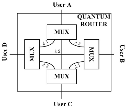
is a block diagram of a 4 ports “quantum router” which is made up of 4 MUXs. Each MUX has 3 demultiplexing ports and 1 multiplexing port. All demultiplexing ports of 4 MUXs connect with each other by fibers. The connection scheme satisfy that any two MUXs have one and only one link which transfer same wavelength signals. Each multiplexing port connects with one user by arterial fiber. All users and the “quantum router” compose a QKD star-network. This type of network with any amount of users can also be setup. The connection scheme of MUXs accords with edge coloring theorem in graph theory.Diestel (2005) Each MUX corresponds to a vertex of graph, each link corresponds to an edge, and each wavelength corresponds to a color. The edge coloring theorem says: for a complete graph with N nodes, when N is even, it needs N-1 colors to color each edge so that adjacent edges (edges which has same vertex) have different colors; when N is odd, the amount of colors is N. That means, for a N ports “quantum router”, each MUX needs N-1 or N demultiplexing ports to finish the connection.
Here we give a simple way to find the right connection scheme for odd or even nodes router. As shown in FIG. 2,
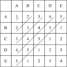
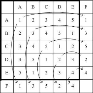
the capital letters represent MUXs and Arabic numerals represent wavelengths. The tables in the figure indicate the connecting relation between MUXs. For example, the number 2 in row A and in line B means connect A and B by wavelength 2. The process of finishing these tables is: when N is odd, e.g. N=5 such as in fig.2(a), fill the blanks along 45° diagonal with numbers 1 to N in turn, and when it reaches N, go back to 1 and fill the rest blanks just as above; when N is even, e.g. N=6 such as in fig.2(b), use said method to fill a N-1 table first, and then copy 135° diagonal numbers to last row from left to right and last line from up to down.
Because this “quantum router” is made up of MUXs, its performance depends on that of MUXs. Up to date, the arrayed waveguide gratings (AWG) and thin film interference filters WDM are gaining prominence. Filters offer good stability and isolation between channels at moderate cost, but with a high insertion loss. AWGs exhibit a flat spectral response and low insertion loss, and they are also better for large channel counts, where the use of cascaded thin film filters is impractical.
For one thing, MUXs’ capability will impact the size of network. The maximum nodes of a network depends on the max amount of channels of MUX. The popular dense WDM product has 40 channels, and 4200 channels have been achieved in laboratory.Takada et al. (2002) That means it is possible to build a “quantum router” with 4200 ports in future. Consider that the absolutely secure communication is not as popular as internet, this QKD net size may be enough for a big city.
Secondly, the insertion loss will reduce the efficient QKD distance. Since signals will pass through MUX twice when they pass the “quantum router”, the insertion loss of “quantum router” is double. The insertion loss of popular product is 5 dB, so it is 10 dB of “quantum router”. According to the performance of present point-to-point QKD system, we can build a QKD network over 50 km at least. That will still meet the requirement of a big city. Along with the development of WDM technology, the insertion loss will be less than 1 dB in future,Smit (2005) and then the quantum network will cover more than 100 km.
The third problem is crosstalk. For a network, crosstalk will bring bit errors, so it must be reduced as low as possible. We think it can be estimated as follow: The insertion loss () and crosstalk () is:
| (1) |
| (2) |
Here and are input and output probability of single photons, is output probability of photons with wavelength which export from port j, is output probability of photons with wavelength which export from port i. in equation 2 equal to in equation 1
| (3) |
| (4) |
We first assume that all input probability of single photons from any user is same when they enter the “quantum router”, since one photon will pass through two MUXs when it pass “quantum router”, crosstalk versus efficient signals is:
| (5) |
Now we consider the situation that the probability of input photons is not the same. A terrible situation is that input photons which produce efficient signals pass through a fiber that has X dB insertion loss before pass through “quantum router” but those photons which produce crosstalk do not. The ratio in equation 5 will become . If there are many inputs that produce crosstalk, the ratio must be , here is the amount of channels. For popular product, , (when ), (when ), . The ratio is less than 0.056%. So the errors brought by crosstalk are less than other affect and can be ignored. Along with the development of WDM technology, crosstalk will be smaller and the performance of “quantum router” will improve.
In this paper we provide a new scheme of QKD network. The kernel part of this network is “quantum router” which is made up of MUXs. Base on present WDM technology and combine with point-to-point QKD system, we can easily build a feasible QKD network over 50 km with 40 users.
This work was funded by National Knowledge Innovation Program piloted at CAS, National Natural Science Foundation of China (60537020) and National Science Foundation for Innovative Research Group (60121503).
References
- Bennett and Brassard (1984) C. H. Bennett and G. Brassard, in Proceedings of IEEE International Conference on Computers, Systems and Signal Processing (Bangalore, India, 1984), p. 175.
- Bennett (1992) C. H. Bennett, Phys. Rev. Lett. 68, 3121 (1992).
- Ekert (1991) A. K. Ekert, Phys. Rev. Lett. 67, 661 (1991).
- Stucki et al. (2002) D. Stucki, N. Gisin, O. Guinnard, G. Ribordy, and H. Zbinden, New J. Phys. 4, 41 (2002).
- Gobby et al. (2004) C. Gobby, Z. L. Yuan, and A. J. Shields, Appl. Phys. Lett. 84, 3762 (2004).
- Han et al. (2005) Z.-F. Han, X.-F. Mo, Y.-Z. Gui, and G.-C. Guo, Appl. Phys. Lett. 86, 221103 (2005).
- Mo et al. (2005) X.-F. Mo, B. Zhu, Z.-F. Han, Y.-Z. Gui, and G.-C. Guo, Opt. Lett. 30, 2632 (2005).
- Townsend et al. (1994) P. Townsend, S. Phoenix, K. J. Blow, and S. Barnett, Electron. Lett. 30, 1875 (1994).
- Townsend (1997) P. D. Townsend, Nature 385, 47 (1997).
- Elliott (2002) C. Elliott, New J. Phys. 4, 46 (2002).
- Elliott et al. (2005) C. Elliott, A. Colvin, D. Pearson, O. Pikalo, J. Schlafer, and H. Yeh (2005), quant-ph/0503058.
- YOSHIHIRO and AKIHISA (2003) N. YOSHIHIRO and T. AKIHISA (2003), no.2003-018144.
- Diestel (2005) R. Diestel, Graph Theory (Springer-Verlag, 2005), URL http://www.math.uni-hamburg.de/home/diestel/books/graph.theor%y/.
- Takada et al. (2002) K. Takada, M. Abe, T. Shibata, and K. Okamoto, Electron. Lett. 38, 572 (2002).
- Smit (2005) M. K. Smit, in PROCEEDINGS OF WFOPC 2005: 4TH IEEE/LEOS WORKSHOP ON FIBRES AND OPTICAL PASSIVE COMPONENTS, edited by R. S and A. M (2005), p. 26.