Also at ]Laboratoire d’informatique théorique et quantique, Université de Montréal, C.P. 6128, Succ. Centre-Ville, Montréal (QC), H3C 3J7 Canada
Deterministic unitary operations on time-bin qudits for quantum communication
Abstract
We show for the first time how deterministic unitary operations on time-bin qubits encoded in single photon pulses can be realized using fiber optics components that are available with current technology. We also generalize this result to operations on time-bin qudits, i.e. -level systems, and show that this can be done efficiently using 22 beamsplitters and phase modulators. Important benefits for experimental quantum communication are highlighted. This work shows how to bridge the gap between current proof-of-principle demonstrations and complete, deterministic experiments.
pacs:
03.67.Hk, 03.67.Dd, 42.81.-i, 42.50.Xa, 03.67.LxQuantum information science is rooted in the idea that information can be encoded and processed in qubits, i.e. two-level quantum systems Nielsen and Chuang (2000). Recently, this fruitful proposition led to important theoretical results in the field of quantum communication along with experimental demonstrations of quantum cryptography Bennett and Brassard (1984), quantum repeaters Briegel et al. (1998), tests of Bell’s theorem Bell (1964) and quantum teleportation Bennett et al. (1993) (see Ref. Tittel and Weihs, 2001 for a review). Moreover, there are now numerous proposals benefiting from the use of qudits (-level quantum systems). In cryptography, qudits increase the tolerance to noise Cerf et al. (2002) and in quantum communication, they improve channel capacity Fujiwara et al. (2003). When entangled, they enhance the security bounds for coin flipping Ambainis (2001), they reduce the communication complexity below the classical limit Časlav Brukner et al. (2002) and they give a solution to the Byzantine agreement problem Fitzi et al. (2001). Entangled qudits are also useful for testing Bell’s theorem by providing a stronger violation Kaszlikowski et al. (2000) and a greater robustness against noise Collins et al. (2002).
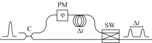
Photons and optical fiber are natural candidates to implement quantum communication protocols and for this purpose, the time-bin encoding for qubits is proven to be very robust and practical Bennett (1992); Brendel et al. (1999). To generate a time-bin qubit, a single photon pulse is first split in two rails using a 22 coupler (the all-fiber equivalent of a beamsplitter) as shown on Fig. 1. Then, each component travels through either the “short” or “long” rails. Finally, both are time-multiplexed in the same fiber using a 21 optical switch. At the output, the single photon is in a coherent superposition of being in two time-bins separated by a delay : . By changing the coupling ratio of the coupler and the phase delay of the phase modulator, all pure qubit states can be generated. Time-bin entanglement in the state can also be generated efficiently using spontaneous parametric downconversion Brendel et al. (1999). This type of entanglement has been shown to be robust against polarization mode dispersion, phase fluctuations and chromatic dispersion over at least 50 km of transmission in optical fiber Marcikic et al. (2004); Fasel et al. (2004).
The main difficulty with time-bin encoding is that both single qubit unitary operations and measurements in any basis are not trivial to implement. Actually, most of the experiments done so far use non-deterministic operations with post-selection Gisin et al. (2002); Marcikic et al. (2003); Tittel and Weihs (2001) and this reduces the success rate, if not leading to a complete failure. For example, complete quantum teleportation of a time-bin qubit cannot be achieved without using deterministic single qubit operations to correct the teleported state Marcikic et al. (2003). A similar problem exists in the experiments testing Bell’s theorem with time-bin qubits as we discuss below. Also, multi-user protocols requiring cascaded operations on the same qubit are not scalable when limited to probabilistic operations. The ubiquitous need for single time-bin qubit and qudit deterministic operations for quantum communication and the lack of any general scheme to do this are the motivations of this work. In this letter, we extend on our work of Ref. Bussières et al., 2006 and propose different experimental schemes to perform deterministic unitary operations on time-bin qubits and qudits using photons. These schemes can be implemented with technology that is currently available. Throughout the text, the schemes are presented with single mode optical fiber circuits and wavelengths around 1550 nm. Nevertheless, they can be directly adapted to any kind of waveguide or free-space transmission.
All unitary operations on a single polarization qubit are easy to implement using an all-fiber polarization controller. The first scheme we propose takes advantage of this by converting a time-bin qubit to a polarization qubit to perform the operation and then converting back to a time-bin qubit for transmission.
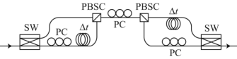
The gate is shown on Fig. 2. First, a single photon in a time-bin qubit state with a given polarization, say horizontal (H), is incident from the left on the 12 switch which routes the and the components to the lower and upper rails respectively. The polarization of the lower rail is flipped to vertical (V) by a polarization controller and is also delayed by . This delay synchronizes the and components at the inputs of the polarizing beam splitter/combiner (PBSC). The latter reflects and transmits V and H polarizations, hence, the time-bin qubit is converted to a single-rail polarization qubit according to the mapping and . Then, the output of the PBSC is fed into an all-fiber polarization controller that transforms any polarization to any other with negligible loss. After the rotation, the polarization qubit is converted back to an H polarized time-bin qubit using the inverse of the operation done in the first section. Therefore, this gate can implement all unitary operations on a single time-bin qubit.
To implement a given operation, the switches are the only active components. The faster the switching speed, the smaller is the required separation between the and components, thus, the smaller is the required path length difference. With current technology, electrooptic material allow for switching frequencies of at least 10 GHz, hence, the path length difference can be set at about 2 cm in standard single mode fiber. This is crucial since the relative phase between the branches has to be stabilized in temperature. A path difference of 2 cm would require the temperature to be stable within 1 tenth of a degree Kelvin at room temperature, which is not difficult to achieve in the laboratory. The two PBSC can be fabricated with fused fiber couplers and are therefore practically lossless Aubé et al. (2005). The major limiting factor is the insertion loss of the switches caused mainly by the mode mismatch between the fiber core and the waveguide of the switch. With current technology, this loss can be lowered down to about 1.5 dB for a total of 3 dB for the whole gate.
The second scheme for deterministic operations we propose works by converting the time-bin qubit to a dual-rail qubit for processing Chuang and Yamamoto (1995). The gate is pictured in Fig. 3 and works as follows. A time-bin qubit is incident from the left on a 12 optical switch that routes the and the components to the upper and lower rails respectively.
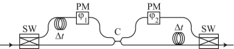
Next, the upper rail is delayed by to synchronize with and consequently, the photon is converted to the dual-rail encoding: and , where the labels and stand for the upper and lower rails respectively. The two components of the single photon interfere at the coupler set to a specific coupling ratio to implement a given gate. This, supplemented with two phase modulators, can implement any unitary operation on the dual-rail qubit. The remaining part of the gate converts the dual-rail qubit back to a single-rail time-bin qubit. Therefore, this gate can implement all unitary operations on a single time-bin qubit.
To implement a given operation, the switches are the only active components and the temperature requirements are the same as in the previous scheme. Moveover, stable and precise phase modulators can be made lossless using piezoactuators glued on the fiber. Finally, the typical loss of an all-fiber coupler is of the order of 0.1 dB or less. Therefore, the only important sources of loss are the switches and again, it can be lowered down to about 3 dB in total. The main advantage of this scheme over the previous one is that it can be made insensitive to alignment if polarization independent switches are used. Also, this scheme is well suited for tasks that require ultra-fast and deterministic feedforward processing like quantum teleportation. Indeed, an ultra-fast tunable coupler can be made with a Mach-Zehnder interferometer using an eletrooptic phase modulator in one of its arms, hence yielding a single circuit that can implement all operations. Using theses ideas, we have shown how the cluster state model of quantum computation can be implemented in optical fiber circuits Soudagar et al. (2006).
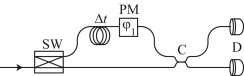
We now discuss how this scheme is useful for testing Bell’s theorem Bell (1964) with time-bin qubits. The robustness of time-bin entanglement over fiber transmission is clearly an advantage to eliminate the locality loophole. However, the detection loophole cannot be closed without using deterministic measurements in the time-bin basis. Indeed, this is essential to overcome the 83% detection efficiency threshold needed to achieve a loophole free violation of the CHSH inequality Garg and Mermin (1987). To eliminate the detection loophole using the schemes proposed here, one uses the dual-rail gate of Fig. 3 modified such that two detectors are placed on the rails right after the coupler, as shown on Fig. 4. To deterministically measure in any desired basis, one can set the correct values for the coupling ratio and the phase . Hence, in principle, a simultaneous closure of the detection and locality loopholes is possible using this setup. Encouragingly, we note that a noiseless photon detector with 88% detection efficiency at 1550 nm is now available Rosenberg et al. (2005). With the improvements on optical components, it is reasonable to hope that a loophole free experiment using time-bin qubits and deterministic measurements will be performed in the near future.
Before generalizing to deterministic operations on -level systems, we mention that time-bin qudits can be generated with a setup similar to the one described in Fig. 1, where the single photon is split into rails instead of two, all of which are time-multiplexed in one fiber using a 1 switch. Moreover, entangled time-bin qudits have been successfully generated using a mode-locked laser Stucki et al. (2005).
The generalization to qudit operations is based on the following results: 1 - Time-bin qudits can be easily converted to rail qudits by demultiplexing the bins in rails using a switch and by synchronizing all the components with delay lines, 2 - Arbitrary unitary operations on rail qudits can be implemented using 22 couplers only Reck et al. (1994). We describe the second result in detail. Consider a single photon in a superposition of being in rails labelled 1 to . Let be the transfer matrix of a lossless 22 coupler mixing rails and and let be the mathematical extension of to a unitary matrix acting only on the subspace of rails and . More precisely, consists of the identity matrix with elements , , and replaced by the elements of . In Ref. Reck et al., 1994, it is shown that any -dimensional unitary transfer matrix U() can be factorized in a sequence of matrices. The decomposition is written as
| (1) |
where is a sequence of coupler matices sequentially mixing rails and , and , and so on until and 1:
| (2) |
The decomposition is similar for , …, . The matrix is a phase correction applied to each mode and requires phase modulators. Hence, a maximum of couplers are necessary to implement any U() in the -rail encoding. As time-bin qudits can always be converted to rail qudits and vice versa, any U() can be implemented in the time-bin encoding.
To exemplify our proposition, we illustrate how it can be used to implement the deterministic measurements of the quantum key distribution protocol using qutrits proposed in Ref. Bechmann-Pasquinucci and Peres, 2000. This protocol was shown to be more robust to noise than the BB84 protocol using qubits Cerf et al. (2002). To generate a key bit, Alice chooses randomly one qutrit state among twelve that are part of four mutually unbiased basis and sends it to Bob. Let be the first orthogonal basis. The second basis can be taken as
| (3) | |||||
| (4) | |||||
| (5) |
The third and fourth basis are given by the cyclic permutations of the following states, respectively:
| (6) | |||
| (7) |
Upon reception, Bob measures the qutrit in one of the four randomly chosen basis. If the bases match, Alice and Bob keep the results. With time-bin qutrits, Bob can take the first basis to be the time of arrival of the photons. In this case, measurements require only one photon detector and a time frame shared with Alice. However, to measure in the second basis, Bob needs an interferometric setup to apply the unitary transformation in the time-bin encoding, where , before measuring with his detector. The matrix is given by
| (8) |
Using equation (1), is factorized as
| (9) |
where the 22 matrices associated with , and are
| (12) | |||||
| (15) | |||||
| (18) |
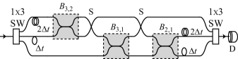
The fiber optic circuit implementing is shown in Fig. 5. First, a 13 switch along with delays of and are used to convert the incoming time-bin qutrit to a rail qutrit on which the transformation is applied using three couplers shown in dashed boxes. In the final section, the resulting qutrit is converted back to the time-bin encoding using a 31 switch. The phase correction is not necessary in this case since detection occurs right after the gate. To measure in the third and fourth basis, it is easy to show that Bob can use the same setup supplemented with phase modulators inserted on all rails between the couplers.
In this letter, we have shown how deterministic unitary operations on single time-bin qubits encoded in photons can be implemented with current optical fiber technology. This also allows to implement deterministic measurements in any basis. Finally the generalization to deterministic operations on time-bin qudits was presented. Ultimately, the schemes are technologically limited by the loss of the switches. Since no physical reason limits the improvements of current optical switches, it is reasonable to believe that experimental quantum communication with time-bin qudits using the schemes presented here will become highly practical in the near future. Future work will focus on the experimental realization of the proposed schemes and on the application to deterministic quantum communication experiments.
Acknowledgements.
Financial support by the Natural Sciences and Engineering Research Council of Canada (NSERC) and by the Canadian Institute for Photonics Innovations (CIPI) is acknowledged.References
- Nielsen and Chuang (2000) M. A. Nielsen and I. L. Chuang, Quantum Computation and Quantum Information (Cambridge, 2000).
- Bennett and Brassard (1984) C. H. Bennett and G. Brassard, in Proc. of the IEEE Int. conf. on Computers, Systems & Signal Processing, Bangalore, India, 1984 (IEEE, New York, 1984), p. 175.
- Briegel et al. (1998) H.-J. Briegel, W. Dür, J. I. Cirac, and P. Zoller, Phys. Rev. Lett. 81, 5932 (1998).
- Bell (1964) J. S. Bell, Physics 1, 195 (1964).
- Bennett et al. (1993) C. H. Bennett, G. Brassard, C. Crépeau, R. Jozsa, A. Peres, and W. K. Wootters, Phys. Rev. Lett. 70, 1895 (1993).
- Tittel and Weihs (2001) W. Tittel and G. Weihs, Quantum Inf. and Comp. 1, 3 (2001).
- Cerf et al. (2002) N. J. Cerf, M. Bourennane, A. Karlsson, and N. Gisin, Phys. Rev. Lett. 88, 127902 (2002).
- Fujiwara et al. (2003) M. Fujiwara, M. Takeoka, J. Mizuno, and M. Sasaki, Phys. Rev. Lett. 90, 167906 (2003).
- Ambainis (2001) A. Ambainis, in Proceedings of the 33rd Annual ACM Symposium on Theory of Computing (STOC’01) (ACM Press, New York, 2001), pp. 134–142.
- Časlav Brukner et al. (2002) Časlav Brukner, M. Żukowski, and A. Zeilinger, Phys. Rev. Lett. 89, 197901 (2002).
- Fitzi et al. (2001) M. Fitzi, N. Gisin, and U. Maurer, Phys. Rev. Lett. 87, 217901 (2001).
- Kaszlikowski et al. (2000) D. Kaszlikowski, P. Gnaciński, M. Żukowski, W. Miklaszewski, and A. Zeilinger, Phys. Rev. Lett. 85, 4418 (2000).
- Collins et al. (2002) D. Collins, N. Gisin, N. Linden, S. Massar, and S. Popescu, Phys. Rev. Lett. 88, 040404 (2002).
- Bennett (1992) C. H. Bennett, Phys. Rev. Lett. 68, 3121 (1992).
- Brendel et al. (1999) J. Brendel, N. Gisin, W. Tittel, and H. Zbinden, Phys. Rev. Lett. 82, 2594 (1999).
- Marcikic et al. (2004) I. Marcikic, H. de Riedmatten, W. Tittel, H. Zbinden, M. Legré, and N. Gisin, Phys. Rev. Lett. 93, 180502 (2004).
- Fasel et al. (2004) S. Fasel, N. Gisin, G. Ribordy, and H. Zbinden, Eur. Phys. J. D 30, 143 (2004).
- Gisin et al. (2002) N. Gisin, G. Ribordy, W. Tittel, and H. Zbinden, Rev. of Mod. Phys. 74, 145 (2002).
- Marcikic et al. (2003) I. Marcikic, H. de Riedmatten, W. Tittel, H. Zbinden, and N. Gisin, Nature 421, 509 (2003).
- Bussières et al. (2006) F. Bussières, Y. Soudagar, G. Berlin, S. Lacroix, and N. Godbout, in Proc. of IEEE (to be published) (2006).
- Aubé et al. (2005) M. Aubé, A. Boucon, B. Burgoyne, X. Daxhelet, A. Dupuis, N. Godbout, F. Gonthier, S. Lacroix, M.-E. Leclerc, F. Seguin, et al., Photons: The Technical Review of the Canadian Institute for Photonics Innovations, Spring 2005 (2005).
- Chuang and Yamamoto (1995) I. L. Chuang and Y. Yamamoto, Phys. Rev. A 52, 3489 (1995).
- Soudagar et al. (2006) Y. Soudagar, F. Bussières, G. Berlin, S. Lacroix, J. M. Fernandez, and N. Godbout, JOSA B (to be published) (2006).
- Garg and Mermin (1987) A. Garg and N. D. Mermin, Phys. Rev. D 35, 3831 (1987).
- Rosenberg et al. (2005) D. Rosenberg, A. E. Lita, A. J. Miller, and S. W. Nam, Phys. Rev. A 71, 061803(R) (2005).
- Stucki et al. (2005) D. Stucki, H. Zbinden, and N. Gisin, J. of Mod. Optics 52, 2637 (2005).
- Reck et al. (1994) M. Reck, A. Zeilinger, H. J. Bernstein, and P. Bertani, Phys. Rev. Lett. 73, 58 (1994).
- Bechmann-Pasquinucci and Peres (2000) H. Bechmann-Pasquinucci and A. Peres, Phys. Rev. Lett. 85, 3313 (2000).