1in1in1in1in
Techniques for the Synthesis of Reversible Toffoli Networks
Abstract
This paper presents novel techniques for the synthesis of reversible networks of Toffoli gates, as well as improvements to previous methods. Gate count and technology oriented cost metrics are used. Our synthesis techniques are independent of the cost metrics. Two new iterative synthesis procedure employing Reed-Muller spectra are introduced and shown to complement earlier synthesis approaches. The template simplification suggested in earlier work is enhanced through introduction of a faster and more efficient template application algorithm, updated (shorter) classification of the templates, and presentation of the new templates of sizes 7 and 9. A novel “resynthesis” approach is introduced wherein a sequence of gates is chosen from a network, and the reversible specification it realizes is resynthesized as an independent problem in hopes of reducing the network cost. Empirical results are presented to show that the methods are effective both in terms of the realization of all reversible functions and larger reversible benchmark specifications.
1 Introduction
The synthesis of reversible networks has received much attention in recent years [28, 2, 8, 13, 14, 18, 19, 24]. There are two primary motivations for this. One is power consumption. Landauer [9] showed that irreversible circuits must consume power, and consequently dissipate heat, whenever they erase or otherwise discard information. Further, Bennett [4] showed that for power not to be dissipated in an arbitrary circuit, it must be built from reversible gates. While the heat generation due to the information loss in modern CMOS is still small, recent work by Zhirnov et al. [29] shows the potentially prohibitive difficulty of heat removal with the increasing density of CMOS. The second motivator is that all quantum gates are reversible [21].
Hence there are compelling reasons to consider circuits composed of reversible gates and the synthesis of such networks. Reversible circuit techniques are of direct interest in low-power CMOS design [23], quantum computing [21], and nanotechnology [17, 16]. Quantum computing seems to be the most promising technology in terms of its potential practical use. As a tribute to this fact, we wrote our software with an option of minimizing the gate count or a quantum cost (in fact, any weighted gate count type cost) of the resulting implementation. Research on reversible synthesis is of particular importance to the development of quantum circuit construction (in particular, oracles) and may well result in much more powerful computers and computations.
In this paper, we develop a set of techniques for the reversible circuit synthesis and present a CAD tool. Due to the small size of the modern quantum processor (state of the art quantum processor can work with 7 qubits [1]; and, there is a limited control over a 12-qubit processor [20]), difficulty in constructing a reliable implementation of the gates in existing hardware, quantum errors and decoherence, this is how we addressed the CAD tool designer’s challenge:
-
1.
Reliability: We present a synthesis approach and its software realization that always finds a solution (network). We motivate it such that for the people using a CAD tool, it is important to get a network no matter how “difficult” the function they synthesize is.
-
2.
Scalability: Our software can be applied to the functions with up to 21 variables in reasonable time. While this number is not large, it is 3 times (almost twice in case of [20] and limited control) greater than the size of the best modern quantum processor. This is more than enough for the present needs. We store a function as a truth table which has to fit in memory — this limits the scalability of our approach. In Section 9 we indicate how to improve the existing software so as to allow synthesis of larger specifications. To date, we did not find it useful to pay much attention to further scalability.
-
3.
Quality: Small networks are always in favor, especially on the early stage of the development of a technology. Specifics of quantum technology include limited computational time due to decoherence and inaccuracy in applying the gates leading to accumulation of the errors, among a number of other issues. Thus, it is much more important to create smaller designs for quantum technology, as compared to, for instance, CMOS. Most of our attention has been put to decrease the cost of the final implementation. Results shown in Section 8 indicate that we succeeded in this direction.
-
4.
Runtime: Some of our designs may take up to 12 hours to synthesize on an Athlon 2400XP machine with 512M of RAM memory running Windows. However, in Section 8 we discuss how to speed up our tool 6 times on a 6-processor parallel machine. Optimization of the code (which, in its present form is not optimized), using a newer compiler (ours is as of 1996), and a more recent computer system would also contribute to the runtime reduction. We found that our present realization satisfies the market needs as is, in the sense that 12 hours for synthesis compare favorably to the 4 years of no progress in the development of larger quantum processors.
In this paper, we present novel techniques for the synthesis of reversible networks of Toffoli gates as well as improving on some existing techniques. Section 2 provides the necessary background. In Section 3, we present a new synthesis approach which selects Toffoli gates so that the complexity of the Reed-Muller spectra specifying the reversible function is iteratively reduced until the specification becomes the identity. The complexity is based on the number of nonzero coefficients in the spectra. This method does not always find a solution, but it frequently finds better solutions than those found by earlier methods such as the one presented in [14]. We follow this section by description of a second Reed-Muller spectra based synthesis algorithm (Section 4). A significant advantage of this algorithm is its guaranteed convergence, and lesser quantum cost in the worst case scenario as compared to the previously presented methods [24, 14]. Together the new Reed-Muller techniques and the earlier approach in [14] yield significantly improved results.
As presented in [14], once an initial network is found, it can often be simplified through the application of templates. In Section 6, we present an improved approach to templates including classification of the templates of size up to 7 and some useful templates of size 9. We noticed that the template matching algorithm of [14] is not very efficient, and replace it with a new one. Our new matching algorithm is better in the sense that, unlike the previous algorithm, under certain conditions it is guaranteed to find all possible network reductions that such a templates based tool can find, plus, it works faster.
A new “resynthesis” approach is presented in Section 7. This method depends on the fact that any sequence of gates in a reversible network on its own realizes a reversible specification. The method randomly (under some constraints) selects a sequence of gates from a network and then applies synthesis methods and the templates to the reversible function defined by that sequence. If the network found by resynthesis is smaller, it replaces the selected sequence in the original network. While our current approach to resynthesis is rather naive, it does significantly reduce the size of the network in many instances, particularly for some of the larger benchmark problems.
Empirical results are given in Section 8. Our methods are shown to produce an excellent overall average for the synthesis of all reversible functions, only above the optimum. We also present the results of applying our methods to a number of larger benchmark functions. The paper concludes with suggestions for ongoing research.
2 Background
Definition 1.
An -input, -output, totally-specified Boolean function is reversible if it is a bijection, i.e. each input pattern is mapped to a unique output pattern.
Using methods such as in [13, 18, 28] a (possibly incompletely-specified) multiple-output Boolean function can be transformed into a reversible function. These methods are not particularly efficient and it is an open research problem to find better ways to perform such a transformation while minimizing the overhead due to addition of “constant inputs” and “garbage outputs” [6]. In this work, we assume a reversible specification as the starting point.
Given a reversible specification, there are many ways (e.g. [28, 19, 2, 8, 14]) of constructing a reversible network using the multiple control Toffoli gates defined as follows:
Definition 2.
For the domain variables the multiple control Toffoli gate has the form , where and . It maps the Boolean pattern to . The set which controls the change of the -th bit is called the set of controls and is called the target.
The most commonly used such gates are: the NOT gate (a multiple control Toffoli gate with no controls) denoted , the CNOT gate (a multiple control Toffoli gate with a single control bit) which is also known as a Feynman gate [5] and is denoted , and the original Toffoli gate (a multiple control Toffoli gate with two controls) denoted [27].
A reversible network is composed of reversible gates, which due to the restrictions dictated by the target technologies [21] form a cascade.
2.1 Cost of a Reversible Toffoli Network
It is a common practice in reversible logic synthesis area [28, 19, 2, 8, 14] to synthesize a network using multiple control Toffoli gates and report its cost as a number of gates in it. However, from the point of view of technological realization, multiple control Toffoli gates are not simple transformations. Rather they are composite gates themselves and Toffoli gates with a large set of controls can be quite expensive [3, 15]. We point out that there are three distinct Toffoli gate simulations [3], one with an exponential cost and requiring no auxiliary bits, and two with linear costs and requiring and auxiliary bits for an -bit Toffoli gate. Due to its exponential size and usage of infinite number of gate types requiring very accurate hardware realization due to the small rotation angles, we find multiple control Toffoli gate simulations with zero auxiliary bits impractical. Among the remaining two linear cost realizations of the Toffoli gates the one associated with availability of auxiliary bits is smaller. [15] improves over the Toffoli gate simulation of [3] using the basis of elementary quantum gates NOT, CNOT, controlled- and its inverse controlled- [21]. Such quantum gates were studied in the literature and were efficiently simulated in liquid state NMR (nuclear magnetic resonance) quantum technology [10].
Definition 3.
Cost of a Toffoli network with inputs/outputs is a sum of costs of its gates, which may sometimes be followed by an asterisk.
-
•
For a network with Toffoli gates of maximal size , each -bit () Toffoli gate cost is a minimum of the two linear cost realization gate counts [15] as long as all associated auxiliary bits can be accommodated in the circuit. In this case, we do not use asterisk.
-
•
For an -bit network containing an -bit Toffoli gate, during the calculation of the cost of each multiple control Toffoli gate we assume presence of an additional auxiliary bit (that is, assume that the network is built on wires). In such case, numeric value of the network cost is followed by an asterisk.
The lesser numeric value of means a better realization.
In this paper, we report two sets of the synthesis results. In one, we minimize the gate count. This is done to compare the quality of our new approach to the quality of the previously presented methods. The second set of results contains networks synthesized as to minimize the quantum cost defined above. In our software implementation, costs of the multiple control Toffoli gates are stored in a table. This allows an easy change of the cost we use to direct the circuit simplification into any other linear cost network metric. To our knowledge, this is the first attempt in the area of reversible logic synthesis to minimize a technological implementation cost instead of the gate count. We believe that network realizations from the second set are more practical.
2.2 Reed-Muller Spectra
Every Boolean function can be uniquely written as a polynomial of the form with Boolean coefficients , which is referred to as the “positive polarity Reed-Muller expansion.” A compact way to represent this expression is the vector (“spectrum”) of coefficients . Given a size reversible function, its Reed-Muller spectra (RM spectra) can be viewed as a table of size , where each column represents the Reed-Muller spectrum of the corresponding output of the reversible function. Note, that for reversible functions the last row of this table is all zeroes and the size of the table can be reduced to . RM spectra can be efficiently computed using fast transform techniques similar to a discrete FFT. The transformation can be expressed in matrix form [26] as
where the summation is modulo-2, i.e. EXOR, and is the truth vector of the given function. In our software, this transformation is implemented by the code shown below which maps a truth vector f[ ] of length given as an array of integers into the RM spectrum for the given function.
void RMT(int f[]){
  int i,j,k,m,p;
  int n = log(LengthOfVector(f[]));

  for (m=1;m<(2*n);m=2*m)
    for (i=0;i<2^n;i=i+2*m)
      for (j=i,p=k=i+m;j<p;j=j+1,k=k+1)
        f[k] = f[k] ^ f[j]; // bitwise EXOR
}
The elements of f[ ] can be multi-bit values with each position representing a separate output function, in which case the procedure computes the output function RM spectra in parallel. Computation of RM spectra in this way is quite efficient for problems with a number of outputs up to the number of bits in an integer for the computer and compiler used.
Important properties of this transformation include:
-
1.
self inverse i.e. ;
-
2.
order dependence in the sense that value is never updated using a value where ;
-
3.
power-of-two independence in the sense that value for is never updated with values of , where and .
The RM spectra of the size identity function with outputs has a single nonzero coefficient for each with all other coefficients 0.
Definition 4.
The RM cost of a reversible function is the total number of coefficients for which its spectra differs from the spectra of the identity function.
We will refer to each nonzero row of the tabular representation of the RM spectra for the identity function as a variable row. Such variable rows are those at positions . We will also refer to all others as non-variable rows.
2.3 Direct Application of a Toffoli Gate in RM Spectra
Application of a multiple control Toffoli gate from the input side of a reversible specification simply requires replacing each occurrence of the literal in the Reed-Muller expansion of the output variable with the expression followed by simplification of the resulting expression. In the case where the Reed-Muller spectra is stored as a table this operation requires at most binary operations with no algebraic simplification. Application of a multiple control Toffoli gate from the output side can also be done directly in the spectra. In particular, the polynomials given by columns (Boolean vectors of length ) of the RM spectra are multiplied and the result is EXORed with column with the result stored in column . Hence, a Toffoli gate can be applied directly while working with the RM spectra. We note that since most reversible functions have numerous zero rows in their tabular RM spectra, it may be more efficient to store the indices and values of non-zero elements of the RM spectra. In this case, application of a Toffoli gate may require significantly less operations. This needs to be pursued but to date we have found the tabular approach sufficient for our work.
3 Iterative Network Synthesis Using Reed-Muller Spectra
The first synthesis algorithm that we propose is very simple. At each step, by exhaustive enumeration it selects the Toffoli gate whose application to the function specification results in the largest decrease of the RM cost. If no gate application decreases the RM cost, a gate is chosen that results in the minimal increase of the RM cost. In both cases, if there is a tie between two or more gates, a gate with the smallest control set is chosen. If there is a tie based on number of controls, our method selects the first gate in lexicographic order.
This synthesis approach is similar to some of earlier proposed techniques [18, 13] in that the gates are assigned to decrease some sort of function complexity measure. However, we use a different gate library and here the Reed-Muller spectrum is used rather than the Walsh spectrum [18] or Hamming distance defined over the truth table [13], resulting in significantly better synthesis results. This is because the Reed-Muller spectrum better corresponds to the functional operation of Toffoli gates.
It is not surprising that there are drawbacks to such a simple approach. When considering larger benchmark specifications, we identified two major problems. First, the algorithm is not guaranteed to converge. In particular, among the functions we tried, it did not converge for the type benchmark functions with more than 5 variables and function . We address this problem by using the other algorithm (that always converges) first and taking its gate count as the upper bound for the synthesis using this algorithm. If the algorithm based on minimization of RM cost does not return a network with fewer gates than the second algorithm that we present below, its solution is considered inefficient. While such a technique appears efficient for the synthesis of benchmark functions, we are working on heuristics to force the Reed-Muller based method to converge on every reversible specification.
The second major problem with the new algorithm is that at each step it tries every possible Toffoli gate, of which there are for a size reversible function. Current implementation of this algorithm uses a table to store the values of RM spectra, making the cost of the search for a single Toffoli gate assignment equal binary operations. In practice, it is likely too time consuming to synthesize functions with more than 12 input variables (especially if the resynthesis technique discussed below is also used). We addressed this issue by having an option to limit the number of controls which every gate that we try might have. We plan to improve the runtime further by first exploring the idea noted above of storing only the nonzero coefficients; and second, searching for heuristics that can guide the selection of a Toffoli gate to avoid the current exhaustive enumeration. Ideas presented in [2, 8] might be useful. Further, we developed another synthesis algorithm that does not have these two major problems. This algorithm is outlined in the next section.
Despite the above deficiencies, the new iterative algorithm by itself converged for every one of the 40,320 reversible functions. It synthesized them with an average of 6.38 Toffoli gates per function in 3 seconds on a single 750 MHz processor Sun Blade 1000. This compares quite favorably to the 7.25 average [14] for the MMD algorithm with no templates applied and shows that the new method has very good potential.
4 MMD Type Reed-Muller Spectra Based Synthesis Approach
The second Reed-Muller based algorithm that we present is similar to MMD [14] in the sense that it works with a single row at a time, and allows a similar bidirectional modification. However, there are a number of differences between MMD and the new algorithm. Some of them are:
-
•
our new algorithm works with Reed-Muller spectra, not in the Boolean domain (truth table) as does MMD;
-
•
the choice of gates while working with a single row is completely different;
-
•
at any point MMD does not change the correct form of upper rows, which is not true for the new method.
We start with a description of the unidirectional (basic) version of the algorithm. It consists of steps (numbered to ). At each step , the first rows (rows with numbers ) in the tabular RM spectra of the function under synthesis match the first rows of the RM spectra of the identity function. The algorithm assigns a (possibly empty) set of Toffoli gates such that the row of the tabular RM spectra is transformed to match the row of the RM spectra of the identity function. It can be observed that for such an algorithm, when step is completed, the RM spectra is transformed to the RM spectra of the identity function, and thus the target specification is successfully synthesized. This is because the row of the RM spectra of a reversible function is always zero. We now describe which gates are assigned depending on the value of and outline a proof showing that a suitable set of gates can always be found. We use to denote the values in a row of the tabular representation for the RM spectra for the reversible function under consideration. We refer to a row as being earlier than another if it has a lower row index number.
A: Step . This step is unique since it is only for this step that we use NOT gates, and there is no need to consider if earlier rows are changed since there are none. Given the 0-th row has values we apply NOT gates for every .
B: Step . Each of these rows is a variable row. Such a row, , has to be brought to the form with 1 at a position . This is done through the following two procedures. We first check if . If it is not, we make it equal one by assigning a gate such that and . According to Lemma 1 such an exists, and it can be easily verified that application of the gate does not affect RM spectra rows earlier in the table.
At this step the row we are working with has the form . We next use gates for every . By applying such gates we do not change rows earlier in the table than the row we are working with and at the same time the row is transformed to the desired form with 1 at position .
C: Step . For these , we know that we are working with a non-variable row. Assume it has values . It has to be transformed to the form , which is the form of each non-variable row of the RM spectra of the identity function. We first find and such that item does not appear in the binary expansion of . In other words, choose a variable whose value in the RM spectra is 1 and that is not included in the product associated with the element of the RM spectra. Such an exists according to Lemma 1. We first apply gates for every . This transforms the row we are working with into with 1 at position . Second, we apply gate , where is a product of variables such that the bit of the binary expansion of the number equals one. Such an operation transforms the row we are working with into the desired . Finally, we undo if such gates changed RM spectra rows earlier in the table than row . Clearly, such “undo” operations do not change the correct form of the pattern we are working with.
To complete the proof of convergence for the above algorithm we need to show that at steps B and C a value with the required properties can always be found. The following Lemma proves this.
Lemma 1.
Suppose the RM spectra of a reversible function has its first rows (rows with numbers ) equal to the first rows of the identity function. Denote the row value by . Then,
-
•
If then .
-
•
If and , then the number defined as is greater than .
-
•
If and , then there exists , such that does not appear in the binary expansion of and .
Proof. First, we prove by contradiction that if , then . Suppose and apply RMT. RMT will transform at position into itself due to the properties 2 and 3 (order dependence and power-of-2 independence) of the RMT and the fact all non-variable rows earlier than the row are zero. According to the property 1 (self inverse) of RMT we are in the Boolean domain now, and we have two rows, the and , both equal to . This is a contradiction since a reversible function can not have two equal rows in its truth table representation.
Proof of the second statement is similarly shown by contradiction by assuming that such an (which does exist as a result of the proof of the first statement) is less than . In that case can be interpreted as a binary expansion of a number since its largest digit is at a position right of . After applying RMT we move to the Boolean domain and find that pattern did not change. At the same time, higher in the table, at position , we will find a pattern equal to . This is the contradiction.
The proof of statement 3 is similar to the above two proofs. Assume such an does not exist. Then, may contain ones only at those positions where the binary expansion of has ones. RMT transforms into , a pattern that may have ones only at positions where the binary expansion of has ones. An equal pattern may be found in the truth table at position , where is an integer with binary expansion . Again having two equal patterns in the truth table is a contradiction.
Example 1.
Consider the 3-variable reversible function specified by the permutation in Boolean domain. The spectra for this function are shown in tabular form in the column labelled RM in Table 1. We want to select Toffoli gates to transform this specification into that of the identity (Table 1, column Id).
The first row of the function specification does not match the first row of the RM spectra of the identity function. This can be fixed by applying the NOT gate . Application of this NOT gate from the output side transforms the specification into the one shown in Table 1, column S1. The first 5 rows in specification S1 match the first 5 rows of the RM spectra of the identity. We need to transform the sixth row from 011 to 000. First, we decrease the number of ones by applying . This leads to specification S2. Note that the third row of S2 has also changed, which means that it has to be updated later. Next, transform the sixth row of S2 into the desired form 000 by applying . This results in specification S3. Finally, undo CNOT gate , which leads to the identity specification and thus the network () was constructed. We again emphasize that the gates have been identified from the output to the input.
| Function | Step1 | Step2 | Step3 | Id | |
|---|---|---|---|---|---|
| Spectral coef. of | cba | cba | cba | cba | cba |
| 1 | 001 | 000 | 000 | 000 | 000 |
| a | 001 | 001 | 001 | 001 | 001 |
| b | 010 | 010 | 011 | 011 | 010 |
| ab | 000 | 000 | 000 | 000 | 000 |
| c | 100 | 100 | 100 | 100 | 100 |
| ac | 011 | 011 | 010 | 000 | 000 |
| bc | 011 | 011 | 010 | 000 | 000 |
| abc | 000 | 000 | 000 | 000 | 000 |
| Gate applied: |
4.1 Bidirectional Method
The following Lemma suggests how a bidirectional modification can be developed.
Lemma 2.
Suppose the RM spectra of a reversible function has its first rows equal to the first rows of the identity function. Then, so does the RM spectra of , the inverse of .
Proof. This statement is, obviously, correct if one works with the truth table representation. In particular, if function maps a pattern into itself in the truth table, so will the inverse function. Due to the property 2 (order dependence) of the RMT the same holds for all .
Assume the first positions in the RM spectra of match the first positions of the RM spectra of the identity, then according to Lemma 2 so do the first positions of the RM spectra of . Hence, every assignment of gates that transforms the row of to match the row of the identity without changing earlier rows (such gates are assigned from the output side of the cascade) will also transform the row for to match the row of the identity. Analogously, an assignment of gates that “fixes” the row for will transform the row of the RM spectra of the identity to its correct form (in this case, the gates are assigned to the input side of the cascade being built). The question of which specification to work with, that of the function, or its inverse is equivalent to the question of which side of the network to assign the gates to, the input side or the output side. This is why we call this modification bidirectional.
In our approach, the decision is based on how small is the cost associated with fixing the row of either RM spectra, that using the function or its inverse. By choosing a smaller cost associated with such transformation we hope to synthesize an overall cheaper network. In the case of a tie, we base our decision on the RM cost of the remaining specification – preference is given to a set of transformations that yield lower RM cost. We base this decision on the belief that on average functions with smaller RM cost are simpler to synthesize. Finally, when these criteria do not resolve the choice, the gates are assigned to the output side (working with RM spectra of the function). Perhaps, better heuristics for the decision of which side to work with can be found, and it would be both interesting and beneficial to explore that.
Theorem 1.
For any reversible function of size the network synthesized by either of the two methods (unidirectional or bidirectional) contains
-
1.
In the multiple control Toffoli gates library: at most NOT gates, at most CNOT gates, and at most Toffoli gates with controls for each .
- 2.
-
3.
In NCV [15] library: at most NOT, CNOT, controlled- and controlled- gates (again, assuming an additional auxiliary bit is available; otherwise the circuit may not be constructible).
Proof. Proof of the first statement is based on an analysis of the basic synthesis algorithm described above. First, at most NOT gates are used at step 0 (A:) of the synthesis algorithm, and none are used thereafter. At most CNOT gates are required at each of the steps (B:), totalling CNOT gates. At each step (C:) at most CNOT gates are required. The number of such steps is , giving a grand total of CNOT gates. Finally, on each step (C:), assuming , at most one multiple control Toffoli gate with control set is used. Calculating the number of such Toffoli gates with controls gives .
Calculation of the result in NCT library is based on multiple control Toffoli gate realizations from [3]. In NCV library, the result is based on multiple control Toffoli gate realizations from [15] and formulas
Item 2 of the above theorem shows a lower upper bound (under the natural assumption that a CNOT gate is no more expensive than a larger Toffoli gate) for our synthesis algorithm as compared to the upper bound of NOT gates, CNOT gates and Toffoli gates for the synthesis algorithm in [24]. We also note another feature of this algorithm that might be useful for a more robust algorithm implementation. Linear reversible functions will always be synthesized using NOT and CNOT (linear) gates only. While synthesizing linear functions, it is sufficient to store only zeroth and all variable rows of its RM spectra. This allows synthesis of size linear reversible functions while making a minimal change to the existing software.
The synthesis algorithm described in this section synthesized all size 3 reversible functions with the average of 6.98 Toffoli gates per function (no templates applied) in 7 seconds on AMD Athlon 2400+ processor. Again, this compares favorably to the 7.25 average for MMD algorithm. For larger benchmark specifications this synthesis algorithm usually constructs smaller quantum cost network as compared to MMD and iterative algorithm discussed in the previous section.
5 Comparison of the New Methods with MMD
In this section we compare performance of the newly presented synthesis methods to the performance of MMD method [14]. Table 2 lists the name and size of a benchmark function tested and the number of gates and quantum cost calculated when synthesis methods MMD, new iterative RM spectra based and new MMD-type RM spectra based are applied. Based on this test we make the following conclusions. The iterative RM spectra based method generally produces smallest circuits for small specifications. However, when tested on larger functions it may diverge (Div.) or take a long time to complete, and thus does not apply (N/A). For larger specifications, RM spectra based MMD type method takes the lead as far as quantum costs are concerned, and application of the original MMD method results in the smallest gate count. In scope of this paper, a smaller quantum cost is more desirable than a smaller gate count, because quantum cost is a better indication of the technological cost of constructing the circuit.
| name | size | MMD GC | MMD QC | Iter. GC | Iter. QC | RM-based GC | RM-based QC |
|---|---|---|---|---|---|---|---|
| 3_17 | 3 | 6 | 14 | 6 | 14 | 7 | 15 |
| 4_49 | 4 | 16 | 72* | 15 | 71* | 20 | 72* |
| 4mod5 | 5 | 9 | 25 | 7 | 15 | 9 | 25 |
| 5mod5 | 6 | 18 | 177* | 12 | 85* | 18 | 177* |
| add3 | 4 | 6 | 18 | 5 | 13 | 6 | 14 |
| cycle10_2 | 12 | 19 | 1206 | 27 | 1569 | 19 | 1206 |
| cycle17_3 | 20 | 48 | 6069 | N/A | N/A | 48 | 6069 |
| ham3 | 3 | 6 | 10 | 7 | 11 | 6 | 10 |
| ham7 | 7 | 25 | 93 | Div. | Div. | 31 | 57 |
| ham15 | 15 | 138 | 2145 | N/A | N/A | 159 | 264 |
| hwb4 | 4 | 18 | 70* | 12 | 48* | 16 | 56* |
| hwb5 | 5 | 57 | 481* | 55 | 569* | 53 | 183 |
| hwb6 | 6 | 134 | 1723* | Div. | Div. | 149 | 816* |
| hwb7 | 7 | 302 | 5528* | Div. | Div. | 435 | 3036* |
| hwb8 | 8 | 688 | 15527* | Div. | Div. | 1101 | 7699* |
| hwb9 | 9 | 1625 | 48384* | Div. | Div. | 2787 | 22284* |
| hwb10 | 10 | 3694 | 124022* | Div. | Div. | 6291 | 49303* |
| hwb11 | 11 | 8312 | 343654* | Div. | Div. | 14566 | 126709* |
| mod5adder | 6 | 37 | 591* | 24 | 242 | 63 | 524* |
| mod1024adder | 20 | 55 | 1575 | N/A | N/A | 55 | 1575 |
| rd53 | 7 | 20 | 181 | 19 | 113 | 19 | 181 |
6 Templates
In previous sections we discussed how to obtain a Toffoli circuit given a function specification. Since optimal synthesis is not feasible, we employed a number of heuristics. The result of heuristic search is, usually, a non-optimal circuit specification. Thus, optimization techniques can be applied to such circuits. In particular, we investigate a form of local optimization technique, called the templates.
Templates are a generalization of rewriting rules. A rewriting rule is defined as a procedure that takes 2 equivalent (computing the same function) circuits and replaces one with the other. If the cost of the part of the circuit to be replaced is greater than the cost of the replacement circuit this leads to a circuit cost reduction. Literature encounters two attempts other than the templates suggesting how the rewriting rules can be used to decrease the gate count in a reversible network [7, 25] and one for quantum circuits [11].
In many reversible logic synthesis papers, the cost of a network is defined as a simple weighted gate count. We refer to this as a linear cost circuit metric. In the more general case of a non-linear cost metric, the cost of the complete circuit does not relate to the gates in a simple linear manner. An example of such a situation can arise when considering Peres gate [22] which, when simulated in quantum technology by a Toffoli gate (cost 5) and a CNOT gate (cost 1) would have a cost of 6, whereas a Peres gate constructed directly in terms of quantum primitives has cost 4. When elementary quantum blocks are decomposed into pulses (as it is done in NMR quantum technology), similar nonlinear cost effects can arise.
We call a rewriting rule regular if the replacement circuit has smaller cost, otherwise we call it irregular. The qualifier regular is omitted when it is clear in context. The idea of applying regular rewriting rules to transform sub-circuits of a given circuit is a powerful tool for circuit cost reduction. (Application of irregular rules may be helpful in techniques like simulated annealing.) The simplification procedure consists of two parts. First, find as many regular rewriting rules as possible, and second, apply them to reduce the cost of a given circuit. Straightforward application of such an approach to quantum circuit cost reduction can be found in [11] and was proposed in [7] for reversible networks composed of multiple control Toffoli gates. However, there are potential problems with this approach in its simplest form.
-
•
The number of regular rewriting rules is very large even for small parameters. For instance, assuming Toffoli type gates have unit cost, the number of regular rewriting rules for reversible binary networks where gates are replaced with gates in a network with input/output variables is 180. It can be easily shown that this number grows exponentially with respect to each of the parameters and .
-
•
Often, rewriting rules are redundant in the sense that a rewriting rule can be a derivative of a rewriting rule if . Further, it can be shown that even the number of non-redundant rules grows exponentially on , and, likely grows exponentially on and (keeping ).
-
•
It can happen that interchanging the order of the gates in a cascade, which is frequently possible and which does not change the linear term cost of a network, may permit application of a rewriting rule that decreases the cost.
The following observations are useful to understanding template approach.
Observation 1. For any network realizing function network is a valid network111Toffoli gates are self inverses: every gate . Thus, template application to the networks with Toffoli gates will not require introducing the new gate types. for the function . This of course includes the case where the cascade of gates realizes the identity in which case the inverse function is also the identity. We use to denote both the identity function and a network realizing the identity function, the meaning being clear from the context.
Observation 2. For any rewriting rule , its gates satisfy the following:
Observation 3. For and any parameter is a rewriting rule. In the most trivial circuit cost metric, where the cost of every gate is 1, i.e. the gate count is calculated, the rewriting rule is regular for parameters in the range
Observation 4. If , then .
Observation 4 allows one to write an identity network with gates in (generally) different ways. We refer to each as a cycle. We are now ready to give the formal definition of the templates.
Definition 5.
A size template is a cascade of gates (a network) that realizes the identity function. For a cascade to be a template, there must be at least one cycle of the gates that can not be reduced in size (gate count) by application of smaller or equal size templates. Only the irreducible cycles are used when applying templates. A template can be applied in either direction:
-
1.
Forward application is a rewriting rule of the form
, where .
-
2.
Backward application is a rewriting rule of the form
, where .
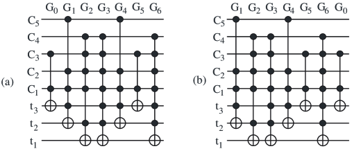
Our earlier template definitions did not require existence of a cycle that cannot be simplified, however, this part of the definition is important. We illustrate this with an example of a size 7 template with two cycles such that one simplifies and the other does not, shown in Figure 1. The network in Figure 1(a) does not simplify whereas the one in Figure 1(b) can be simplified since its rightmost three gates can be replaced with two gates and .
Correctness of the template definition follows from the above four observations. One of the immediate benefits that the templates bring is significant reduction of the space required to store the rewriting rules (this is a significant improvement considering how much space is required in [25] to store some small identities). In fact, one template occupies the same storage space used by a single rewriting rule, yet it is capable of storing up to non-redundant rewriting rules. Assuming the trivial circuit cost metric where each gate has a cost of one, the number of regular non-redundant rewriting rules can be as high as for the odd numbers and for even .
We earlier observed that the number of non-redundant rewriting rules grows exponentially, therefore template classification is highly desirable. Depending on the set of model gates, classifications differ. We consider some of the particular questions and methods of proper classification of Toffoli templates in the next section.
6.1 Toffoli Templates
We wrote a program that helped us find the Toffoli templates. To build templates of size the program first uses depth first search to find optimal networks of maximal sizes and using 3 to 4 input variables (which likely provides enough generality — we do not have a formal proof that it does — to find if a template is missing, but fails to generalize it once a candidate is found). In the second step, the program computes two sets with the truth vectors of functions realizable by cascades of sizes and . Then, for every function in the first set it finds its inverse in the second set. If such a function is found the two networks are combined (use observations 1 and 2 to see that the resulting cascade is always the identity function) and templates of size less than are applied to simplify the cascade. If this leads to a simplification for all cycles, the constructed identity is not a new template. Otherwise, it is a piece of a template and needs generalization.
The algorithm described finds those lines in a template that have targets of the gates, but fails to extract all the possible assignments of the controls. Generalization requires finding all the possible gate controls that apply without changing the network functionality, i.e. leaving it the identity. The following Theorem is useful as it limits the set of choices one can make to assign the controls.
Definition 6.
For any network with an input line that has controls only (control line), its characteristic vector for has ones at positions where the gate has a control, and zeros everywhere else.
Theorem 2.
-
1.
If a control line with the characteristic vector appears in a template of size , any set of lines with this characteristic vector is a valid control set.
-
2.
Lines with characteristic vectors and are valid control lines for any template.
-
3.
If lines with characteristic vectors and are control lines of a template, the line with characteristic vector is also a valid control line.
-
4.
If there exists a line with exactly two EXOR symbols on it, being targets of two gates and , every valid control line has .
Proof.
1. To prove the statement we want to check if the operation of repeating the number of controls of certain type keeps the identity being the identity. Assuming is a valid control line labeled create line of the same type and show that it is a valid control. There are two cases to prove. First, and second, . For the network is equivalent to the network without gates for every . Same thing happens if line is set to zero. In case variable can be completely ignored, which does not change the network functionality. Note, that when any control line is deleted from the template, the resulting cascade still realizes the identity function. This observation is useful in understanding of how a large gate with many controls as shown in the template in Figure 1 can match a relatively small gate in a network to be simplified: the control lines indicate which controls are possible, but may not be necessary for a specific matching.
2. Line with characteristic vector is a “virtual” line whose presence or absence does not change anything. Thus, it can as well be a control. Consider line with characteristic vector . For all the gates do nothing as a control value of zero results in zero value of the corresponding product, and no target line changes its value. Case is equivalent to having a line with zero characteristic vector.
3. Assume line has characteristic vector and line has characteristic vector . Create line with the characteristic vector . We want to prove that setting its values to zero and one does not change the network functionality, that is, it stays the identity. Setting to is equivalent to ignoring value on this line, thus the network will realize the identity. Setting to is equivalent to setting both and to zero. Since and are valid controls, setting them to zero does not change the network output (the network will stay the identity). This means that setting to keeps the network output being equal to its input, so the property of being the identity is conserved, and is a valid control.
4. Prove by contradiction. Suppose there is a control line with characteristic vector such that and prove that in such case the network does not realize the identity. Without loss of generality assume that and . Use Observation 4 to transform network to the form . These two networks can be identities only simultaneously. Now, set the input pattern to have ones on every bit except bit , whose value is set to . Then, gate flips the value of its target bit from to . The only other gate that affects bit is . Since controlling bit of the gate is zero (when propagated control bits do not change their values, and has controls only), gate will not flip its target value . Thus, at the end of the network bit will arrive flipped, which contradicts the statement that network is the identity.
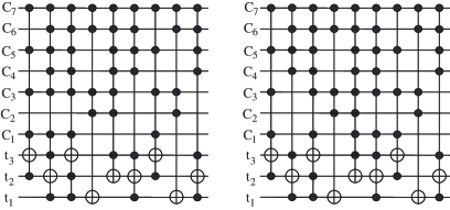
Template generalization is a part of our software package. It is interesting to note that during the generalization process the number of templates may increase. Figure 2 illustrates how a template found by our program (bottom 4 lines: and , ) can be generalized in two different ways.
In [14], we reported a Toffoli network with 4 gates for the 3-bit binary full adder. Assuming the trivial cost metric, we applied our templates. This resulted in no gate count reduction and we can conclude that the network is optimal for the given cost metric (gate count). Prove by contradiction. Suppose it is not. Then, there exists a smaller network for a 3-bit full adder, say with 3 gates. Using Observation 2 one can construct an identity cascade of size 7 built on 4 lines that would differ from the templates and will not be simplified by the means of the templates. Running our template finding program shows that it is impossible, and hence the network is optimal. The following theorem generalizes this observation.
Theorem 3.
For the complete classification of the templates of size up to and their complete (in the sense that no possible application is missed) application to network size reduction:
-
•
For even numbers , each sub-network of size is optimal in any metric. The network itself is optimal if the number of gates is or less.
-
•
For odd numbers , each sub-network of size is optimal in any metric, and each sub-network of size is optimal in the trivial metric. Similar statements hold for the entire network if the number of gates is not greater than or respectively.
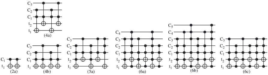
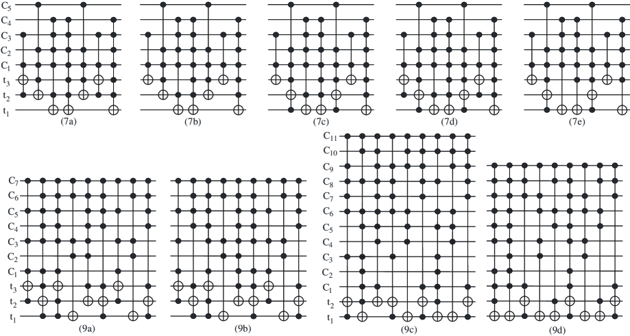
We conclude this subsection with a (most likely, complete) list of the templates of size up to 7 and some templates of size 9, illustrated in Figure 3. Lines in Figure 3 represent each a single line, and lines marked with represent a possibly empty set of lines, all of the same form. We note that the templates of size less than 5 are equivalent to those found in [14]. We report a smaller number of different templates of size 6, as compared to the templates reported in [14]. There are two reasons for that. First, the template illustrated in Fig. 8(d) of [14] is undergeneralized, which we found with the help of our new software. And second, the template classification depends on how the templates are applied. Our algorithm for template application differs from the originally reported ([14]) and is discussed in the following subsection. A quick explanation of why the new algorithm is more accurate at finding more simplification than the original, is that template illustrated in Fig. 8(b) of [14] can now be simplified with the other templates, which was not possible before. This is due to the improved matching algorithm.
6.2 Template Application
To apply templates to circuit cost reduction, we first consider all the templates of the form . Such templates applied for parameter result in the rewriting rule . That is, they define when the two adjacent gates in a cascade can be swapped. We call such templates moving rules and apply them to move the gates in a cascade to permit the application of cost reducing template substitutions. It transpires that for the most network types considered in the literature (binary reversible, MVL reversible, and quantum) the complete description of the templates of form is very simple (this may of course not be true for all gate types). Assuming gate has control(s) and target and gate has control(s) and target these two gates form a moving rule if, and only if, and .
Templates of other size than 4 (and all Toffoli templates of size 4 are the moving rule) are applied as follows. We choose a starting gate for matching. The position of the starting gate () in the matching will change with time, and we begin with . Suppose in a cascade with gates at the present time. We apply smaller templates first. They are easier to match, because one needs to find less gates to do the replacement, and in a sense smaller templates allow more general network transformation (for instance, applying size 2 templates can be thought of as deleting pairs of equal gates, while applying size 9 templates is hard to describe by words). For each of the templates, we match gate in the network to the first gate in each of the cycles of the template, which is always possible. We then try to find the gates in the network that match those in the template assuming the first gate of the template cycle matches this gate in the network and trying both directions for the template application. Next we only explain how to apply a single template cycle in forward direction, because application of other cycles and in backward direction is analogous. At this point, we create two arrays, integer with one element indicating that one gate at position in the network is found and properly matched, and Boolean with one element equal 1 and indicating that all gates can be moved to the one found (in this case no moving is required). In addition, integer indicates that at the present moment we look at the gate . To match more gates, we decrease by 1 and see if gate in the network matches the second gate in the template cycle. If it does, we increase the size of array by 1, and add to it. We increase size of the array and add a new element, 1 to it. Since gate neighbors with gate , there is no need to check if the gates can be moved together. Finally, we check if these 2 gates can be replaced with a smaller network using the present template cycle, and if they can, do the replacement and return . The template matching resumes with starting gate at position and by trying the smallest template first. If gate did not match the second gate in the template, we decrease integer by 1 (it is now equal ) and see if this gate matches the second gate of the template cycle.
In general, if some gates are matched and can be moved together (that is, and where contains a non-zero value indicating that the gates can be moved to the corresponding position), and a gate in a network at position matches gate of the template cycle, the procedure for matching is as follows. First, we check if the gates can be moved together to each of the network positions . If the gates can be moved together, we create array with Boolean values showing where it is possible to move the gates. We next check if it is beneficial to replace the matched and movable together gates with the remaining of the given template. If it is, we do the replacement at the maximal value of an element of , , corresponding to the non-zero value of the and return new . The template matching resumes from this position in the network and the smallest template. If the gates cannot be moved together, we decrease value of the by one and try to match gate at this position in the network. When becomes equal zero or if we cannot match enough gates to do a beneficial replacement using the template, we try to match another cycle, next template of the same size, or a larger template. If no templates match with a starting position , we increase its value by one (start matching with the next gate in the network) until we run out of gates in the network that could serve as a . In such case, template application is completed.
We illustrate how the templates are applied with an example below.
Example 2.
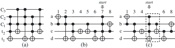
Consider network in Figure 4(b). Suppose and the template cycle that we want to match and apply is as illustrated in Figure 4(a). In the beginning of the matching we have and . Line of the template must correspond to the line of the network, and line should match one of , or — this guarantees that gate 7 matches the first gate of the template cycle. The steps of matching are:
-
•
Let . Gate does not match the second gate of the template cycle in Figure 4(a) since we expect to find a gate with target at a line where gate 7 has a control. Nothing is done, is decreased by 1.
-
•
. Gate 5 matches the second gate of the template if , and . Gate 7 can be moved to gate 5, and gate 5 cannot move to the gate 7. Therefore, becomes . The is . We check that the replacement of the two gates we matched with the three reconstructed from the template is not beneficial, but since has non-zero values, we try to match more gates.
-
•
. Gate in the network does not match the third gate in the template cycle because we are looking for a gate with the target on line .
-
•
. Gate in the network does not match third gate in the given template cycle because we try to find a gate with no control at line .
-
•
. Gate 2 matches the third gate of the template cycle if . Gate 2 can be moved to gate 5, but gate 5 cannot be moved past gate 3. Thus, . and according to the template cycle, these three gates can be replaced with two. It is clearly beneficial to do the replacement. According to the the replacement can be done if all gates are moved to the gate 5 in the network. The network after template application is illustrated in Figure 4(c). Return , because at this position the replacement part (in a dashed box) starts.
The template application resumes starting with the forth gate in the network in Figure 4(c) and trying to apply the smallest template.
In our program realization, function is used to apply templates. It has an option of applying the templates to reduce the gate count or the quantum cost and works according to the algorithm discussed above. We made a modification of the matching algorithm in which we never look for the gates in the network further away from position than 20. This is because we found that in practice the gate span in template application is usually less than 20. Such restriction also makes the template algorithm faster — it is linear in the number of gates in the network. The template application algorithm from [14] has an worst case scenario and best case scenario runtime in terms of the gate count of the circuit to be reduced. The new template application algorithm introduced in this section reduces the circuits better (assuming both algorithms work with the same set of templates) than the one presented in [14], and can be used in conjunction with different circuit cost metrics.
7 Resynthesis Procedure
In our program implementation, we first synthesize a function and its inverse using the MMD method [14] and the newly presented Reed-Muller spectra based algorithms. We then simplify each of the synthesized networks using the templates, choose the smaller network and declare it to be the final implementation. Each subnetwork of the final implementation is itself a network computing some reversible function. This reversible function can be determined and synthesized on its own. If such resynthesis yields a smaller subnetwork, it replaces leading to simplification of the overall network .
We have implemented two drivers for this resynthesis procedure. First, a which performs a user-specified number of iterations. For each iteration, a number (again specified by the user) of random subnetworks are resynthesized and the best overall simplification is chosen and forwarded to the next iteration. Second is an . It tries all possible subnetworks with at least 5 gates of a given network. The requirement of 5 gates is because it is not necessary to resynthesize networks with 4 or less gates, since in our synthesis approach every subnetwork of length 4 is optimal. This result is a corollary of Theorem 3.
When we synthesize networks, random driver is used first. When it does not simplify the network after a few iterations, we run the exhaustive driver (time allowing) to make sure that no sub-network simplifies. The exhaustive driver can take a long time, especially if applied to larger complex functions such as . We did not apply exhaustive driver to the functions of size 16 and greater. Note that using a random driver results in different scenarios for network simplification and the simplified network may differ from one application to the next. It is expected that some of the larger networks considered in Section 8 may be further reduced by multiple applications of the random driver.
8 Results
In the literature, one of the common tests of the quality of a reversible synthesis method is how it performs on the 40,320 reversible functions [14, 2, 8, 14]. We used the 3 synthesis methods that are applied to both function and its inverse, then the templates were applied and the is run until no further simplification is found. This is a time consuming test, and it takes around 96 hours for it to complete. Techniques to reduce the runtime are discussed in Section 9.
Table 3 compares our synthesis results to the earlier reported synthesis algorithms and the optimal results found by depth-first search. It can be seen that our results are significantly closer to the optimal synthesis than the basic MMD algorithm plus templates of maximal size 6 [14] (column MMD), and over twenty times (overhead) as close to the optimum as a recently presented Reed-Muller based tree search algorithm [2] (column AJ). Our results are, on average (WA), only off from the optimal size (column Opt. [24]). It can also be seen that our synthesis results are better than the best presented by Kerntopf [8] (column K), even though that his work uses a larger gate library (given a large gate library one would expect lower gate counts).
| Size | MMD | AJ | Ours | Opt. | K |
| 13 | 6 | ||||
| 12 | 62 | ||||
| 11 | 391 | ||||
| 10 | 1444 | ||||
| 9 | 3837 | 30 | 2 | 86 | |
| 8 | 7274 | 3297 | 659 | 577 | 2740 |
| 7 | 9965 | 12488 | 10367 | 10253 | 11774 |
| 6 | 9086 | 13620 | 16953 | 17049 | 13683 |
| 5 | 5448 | 7503 | 8819 | 8921 | 8068 |
| 4 | 2125 | 2642 | 2780 | 2780 | 3038 |
| 3 | 567 | 625 | 625 | 625 | 781 |
| 2 | 102 | 102 | 102 | 102 | 134 |
| 1 | 12 | 12 | 12 | 12 | 15 |
| 0 | 1 | 1 | 1 | 1 | 1 |
| WA: | 6.801 | 6.101 | 5.875 | 5.866 | 6.010 |
| % | 116% | 104% | 100.16% | 100% | N/A |
Running a synthesis algorithm on all size 3 reversible functions could be an interesting test, but it does not illustrate how the synthesis method applies to large specifications, whose synthesis is the main reason to design an automated procedure. We have applied our synthesis approach to a number of reversible benchmark specifications from [12]222 In our comparison, we considered the networks and function specifications from the above web page. However, our quantum cost calculation differs from the one used in [12], therefore quantum costs reported in Table 4 are slightly different from those that can be found online.. We report two types of the results: we minimize the gate count and we minimize the quantum cost separately. The results are given in Table 4. The name, size, GC and QC columns give the name of each benchmark function, its size (number of variables) of the reversible specification as considered in the literature, the best reported gate count, and the best reported quantum cost for the networks with Toffoli gates. Next two columns report the gate count and the quantum cost when our tool is applied to synthesize a given function with the option of minimizing the gate count. The last two columns report the synthesis results with the option of quantum cost minimization. We find that realizations in the last two columns could be more practical. We note that networks for benchmark functions , , , and network for with quantum cost 79 found in [12] are the results of the techniques discussed in this paper and were not reported before.
Table 4 shows our software synthesize smaller333 [12] contains networks synthesized using Toffoli and Fredkin gates, but we do not compare our results to those in a table form, just mention that the newly presented results are, generally, significantly better. networks than earlier presented heuristics. For instance, the gate count for the benchmark function was reduced from 126 to 42 gates, that is, our network is one third of the size of the best previously presented; and quantum cost for an implementation of this function was reduced more than 10 times.
We limited the search time for our software to 12 hours for each benchmark function. Most functions took significantly less time to synthesize than the allowed 12 hours; most time (12 h) was spend to synthesize only one function, . A general rule was to synthesize a function using all three algorithms, apply the templates, resynthesize with until several iterations do not bring any simplification and apply until no further simplification. In the chosen period of 12 hours, there was no time left to apply to functions (networks for) , , and all networks with 10 and more variables other than and . Due to the time constraints, we did not apply to the networks for and . Our software potentially can synthesize functions with more than 21 variables, but as the number of variables and gates in the synthesized network grows, the runtime for such synthesis grows exponentially.
| Benchmark/its best circuit: | Gate count minimization: | Quantum cost minimization: | |||||
|---|---|---|---|---|---|---|---|
| name | size | GC | QC | GC-gc | QC-gc | GC-qc | QC-qc |
| 3_17 | 3 | 6 | 14 | 6 | 14 | 6 | 14 |
| 4_49 | 4 | 16 | 64* | 12 | 32 | 12 | 32 |
| 4mod5 | 5 | 5 | 13 | 5 | 13 | 5 | 13 |
| 5mod5 | 6 | 10 | 85* | 8 | 77* | 10 | 71* |
| add3 | 4 | 4 | 12 | 4 | 12 | 4 | 12 |
| cycle10_2 | 12 | 19 | 1206 | 19 | 1206 | 19 | 1206 |
| cycle17_3 | 20 | 48 | 6069 | 48 | 6069 | 48 | 6069 |
| cycle18_3 | 21 | N/A | N/A | 51 | 6819 | 51 | 6819 |
| ham3 | 3 | 5 | 9 | 5 | 9 | 5 | 9 |
| ham7 | 7 | 23 | 91 | 21 | 69 | 25 | 49 |
| ham15 | 15 | 132 | 1881 | 70 | 463 | 109 | 214 |
| hwb4 | 4 | 17 | 69* | 11 | 23 | 11 | 23 |
| hwb5 | 5 | 55 | 353* | 24 | 114 | 24 | 114 |
| hwb6 | 6 | 126 | 1519* | 42 | 150 | 42 | 150 |
| hwb7 | 7 | 289 | 5196* | 236 | 3984* | 331 | 2609* |
| hwb8 | 8 | 637 | 14636* | 614 | 12745* | 749 | 6197* |
| hwb9 | 9 | 1544 | 43138* | 1541 | 43089* | 1959 | 20378* |
| hwb10 | 10 | 3631 | 120034* | 3595 | 117460* | 4540 | 46597* |
| hwb11 | 11 | 9314 | 328200* | 8214 | 336369* | 11600 | 122144* |
| mod5adder | 6 | 21 | 145 | 15 | 91 | 17 | 81 |
| mod1024adder | 20 | 55 | 1575 | 55 | 1575 | 55 | 1575 |
| rd53 | 7 | 12 | 128 | 12 | 128 | 16 | 67 |
| rd53 | 7 | 16 | 79 | 12 | 128 | 16 | 67 |
9 Future Work
Our program realization of the discussed methods is no way optimized. We use a resource demanding truth table representation of a function, which, in addition to slowing the software significantly limits the scalability of our implementation. To date, we found that scalability of our approach is satisfactory, however, a more robust function representation must be employed in the future to minimize circuits for the functions with more than 21 variables.
Further work has to be done to optimize the code. For instance, our algorithm can be easily parallelized. Assuming one has a 6 processor machine, each of the 6 networks (3 methods, function and its inverse are synthesized) can be synthesized (including the template application) on a separate processor. Work of and can be distributed evenly among the processors. In total, such algorithm on a parallel machine should be able to run almost 6 times faster as compared to a single processor machine. For large networks, template application can be parallelized by cutting them into small sub-networks and then applying the templates at the cutting points by restricting to grow no more than 20.
Synthesis of incomplete specifications (Boolean multi output functions) is possible using each of the the newly presented synthesis methods, as well as with the old one. This has to be investigated further since most of the real world benchmark functions are irreversible and transforming function specification into a reversible before synthesizing it should not be more effective than the straight synthesis of the multi output specification.
10 Conclusion
In this paper, we presented novel techniques for the synthesis of reversible Toffoli networks. The main contributions include two Reed-Muller spectra based approaches to reversible synthesis; a better characterization of templates and an improved method of their application, classification of the templates of size 7 (most likely, complete) and demonstration of some useful templates of size 9. We also investigated a new approach involving resynthesis of subnetworks that significantly improves the results, particularly for larger benchmark functions. We structured our software as to have an option of minimizing the gate count or a technology-motivated cost. To our knowledge, this is the first attempt to minimize technology motivated cost of the implementation in the relevant literature.
We have implemented our methods in C++ and shown they produce results significantly better than those reported in the literature. Finally, we have identified several ways to improve this work.
References
- [1] IBM’s test-tube quantum computer makes history. Technical report, IBM T.J. Watson Research Center, http://researchweb.watson.ibm.com/resources/news/20011219_quantum.shtml, December 2001.
- [2] A. Agrawal and N. K. Jha. Synthesis of reversible logic. In DATE, pages 21384–21385, Paris, France, February 2004.
- [3] A. Barenco, C. H. Bennett, R. Cleve, D. P. DiVinchenzo, N. Margolus, P. Shor, T. Sleator, J. A. Smolin, and H. Weinfurter. Elementary gates for quantum computation. Physical Review A, 52:3457–3467, 1995.
- [4] C. H. Bennett. Logical reversibility of computation. IBM J. Research and Development, 17:525–532, November 1973.
- [5] R. Feynman. Quantum mechanical computers. Optic News, 11:11–20, 1985.
- [6] N. Gershenfeld and I. L. Chuang. Quantum computing with moleculas. Scientific American, June 1998.
- [7] K. Iwama, Y. Kambayashi, and S. Yamashita. Transformation rules for designing CNOT-based quantum circuits. In DAC, pages 419–424, New Orleans, Louisiana, USA, June 2002.
- [8] P. Kerntopf. A new heuristic algorithm for reversible logic synthesis. In DAC, pages 834–837, June 2004.
- [9] R. Landauer. Irreversibility and heat generation in the computing process. IBM J. Research and Development, 5:183–191, 1961.
- [10] S. Lee, S. J. Lee, T. Kim, J. S. Lee, J. Biamonte, and M. Perkowski. The cost of quantum gates. International Journal of Multi Valued Logic, 2005. In review.
- [11] C. Lomont. Quantum circuit identities. Technical report, quant-ph/0307111, July 2003.
- [12] D. Maslov, G. Dueck, and N. Scott. Reversible logic synthesis benchmarks page. http://www.cs.uvic.ca/~dmaslov/, December 2005.
- [13] D. Maslov and G. W. Dueck. Reversible cascades with minimal garbage. IEEE Transactions on CAD, 23(11):1497–1509, November 2004.
- [14] D. Maslov, G. W. Dueck, and D. M. Miller. Toffoli network synthesis with templates. IEEE Transactions on CAD, 24(6):807–817, June 2005.
- [15] D. Maslov, C. Young, D. M. Miller, and G. W. Dueck. Quantum circuit simplification using templates. In DATE, pages 1208–1213, March 2005.
- [16] R. C. Merkle. Reversible electronic logic using switches. Nanotechnology, 4:21–40, 1993.
- [17] R. C. Merkle. Two types of mechanical reversible logic. Nanotechnology, 4:114–131, 1993.
- [18] D. M. Miller. Spectral and two-place decomposition techniques in reversible logic. In Midwest Symposium on Circuits and Systems, August 2002.
- [19] A. Mishchenko and M. Perkowski. Logic synthesis of reversible wave cascades. In IWLS, pages 197–202, June 2002.
- [20] C. Negrevergne, T. S. Mahesh, C. A. Ryan, M. Ditty, F. Cyr-Racine, W. Power, N. Boulant, T. Havel, D. G. Cory, and R. Laflamme. Benchmarking Quantum Control Methods on a 12-Qubit System. Physical Review Letters, 96(170501), 2006.
- [21] M. Nielsen and I. Chuang. Quantum Computation and Quantum Information. Cambridge University Press, 2000.
- [22] A. Peres. Reversible logic and quantum computers. Physical Review A, 32:3266–3276, 1985.
- [23] G. Schrom. Ultra-Low-Power CMOS Technology. PhD Thesis, Technischen Universität Wien, June 1998.
- [24] V. V. Shende, A. K. Prasad, I. L. Markov, and J. P. Hayes. Synthesis of reversible logic circuits. IEEE Transactions on CAD, 22(6):723–729, June 2003.
- [25] V. V. Shende, A. K. Prasad, K. N. Patel, I. L. Markov, and J. P. Hayes. Scalable simplification of reversible logic circuits. In IWLS, May 2003.
- [26] M. A. Thornton, R. Drechsler, and D. M. Miller. Spectral Techniques in VLSI CAD. Kluwer Academic Publishers, 2001.
- [27] T. Toffoli. Reversible computing. Tech memo MIT/LCS/TM-151, MIT Lab for Comp. Sci, 1980.
- [28] I. M. Tsai and S. Y. Kuo. Quantum boolean circuit construction and layout under locality constraint. In IEEE Conference on Nanotechnology, pages 111–116, 2001.
- [29] V. V. Zhirnov, R. K. Kavin, J. A. Hutchby, and G. I. Bourianoff. Limits to binary logic switch scaling - a Gedanken model. Proceedings of the IEEE, 91(11):1934–1939, November 2003.