Scalable Error Correction in Distributed Ion Trap Computers
Abstract
A major challenge for quantum computation in ion trap systems is scalable integration of error correction and fault tolerance. We analyze a distributed architecture with rapid high fidelity local control within nodes and entangled links between nodes alleviating long-distance transport. We demonstrate fault-tolerant operator measurements which are used for error correction and non-local gates. This scheme is readily applied to linear ion traps which cannot be scaled up beyond a few ions per individual trap but which have access to a probabilistic entanglement mechanism. A proof-of-concept system is presented which is within the reach of current experiment.
pacs:
03.67.-aI Introduction
Quantum Computation (QC) Nielsen poses extreme challenges for coherent control of large-scale quantum systems. Coping with decoherence and imperfect control implies the use the of error correction codes (QEC) and fault tolerant operation. However, maximizing the threshold for arbitrary computation requires the ability to perform multiple, simultaneous operations between qubits and minimal communication and transport overheads. Incorporating these features in a scalable manner is a major goal for all potential system implementations KMW2002 ; MTCCC2005 ; Taylor2005 ; HGFW2005 ; DGH2005 .
A promising candidate for quantum information processing is the ion trap with superb coherence and few qubit control having been already demonstrated LeibfriedEA2005 ; BlattEA2005 . However, it is difficult to effectively control more than a few tens of ions in a single trap, hence several ideas have been proposed to overcome this limitation. Multiple microtraps can be constructed in the same structure with ions shuttled between them (CCD architecture) KMW2002 . The main disadvantage of a CCD trap is the difficulty in designing a micro-trap structure that allows for maximum parallelizability for both inter- and intra-logical operations. Shuttling heats ions up, requiring additional cooling in the interaction regions and slowing operation. Additionally, large numbers of electrodes and lasers would be required in a single device Steane2004 .
Alternatively, ions in separate trap structures may be made to interact via a photonic bus CZKM1997 ; Pellizari1997 ; SL2000 ; KLHLW2003 ; DBMM2004 ; DMMMKM2006 ; vEKCZ1999 . If used directly to implement two-qubit gates, photon loss from the bus is a major problem and requires additional QEC overhead RHG2005 ; RRM2006 . Alternatively, the photonic bus can mediate the generation of entanglement between traps which can then be used to perform gates DB2003 111Cluster state generation for One-Way Computation RB2001 becomes straightforward in this system, local control in each node effectively allows linear scaling BBFM2005 . Failure of an entangling operation does not destroy any prior links, and purification procedures can be used to increase the fidelity of the final cluster state. In this paper however, we will concentrate upon conventional gate-based QC..
The use of entanglement for intra-computer communication is not a new idea. For example, this has been proposed in CCD ion trap designs where EPR pairs are created locally and then the halves sent to entanglement stations distributed among a sea of qubits MTCCC2005 . These entangled pairs would then be used to teleport qubits between memory storage and processing regions, circumventing the problem of directly transporting data across the whole computer. However, since the entangled pairs themselves are created locally and then the separate halves physically moved to where they are required, this neccessitates the use of quantum repeaters and extensive purification. Furthermore in MTCCC2005 , all 49 qubits of a second level encoded logical qubit are teleported requiring many EPR pairs for transport in both directions.

In this paper, we outline an proof-of-concept architecture based around an ion trap processing node containing a relatively small number of ions representing an encoded first level error corrected qubit, ancillas for fault-tolerant operation, and an interface ion which can be entangled with its counterpart in another node (Fig. 1). An abstract basis of the scheme was suggested in DB2003 , but here we analyze a concrete realization, taking particular attention to the requirements of error correction and fault-tolerant operation. In particular, we show how local and non-local logical operations can be reliably performed directly between two nodes via operator measurements, from which scaling to an arbitrary sized quantum computer follows. A small prototype is presented which is within reach of current experiment.
The paper is laid out as follows: The basic architecture is covered in Section II, the use of operator measurements to implement gates is in Section II.1, the preparation of encoded Bell states is in Section II.1.1, fault-tolerant implementation of non-local operators is in Section II.1.2, architecture scale-up is in Section II.2, optimizing node design is in Section III, and concluding remarks in Section IV.
II Architecture
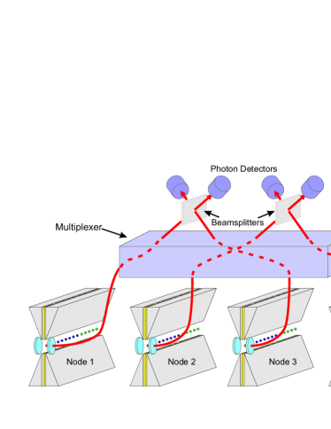
The basic architecture is illustrated in Fig. 2. A network of local processing nodes are connected by optical fibres and a multiplexing switch. In each trap node is a small array of ions upon which conventional single and intra-trap two-qubit operations can be performed. Pairs of nodes can be optically linked to beamsplitters and single photon detectors which entangle the interface qubits when subjected to appropriate laser excitation and conditioned upon a correct sequence of detector clicks. The resulting Bell pair is then be used to perform inter-node operations.
II.1 Operation
We start off with all qubits initialized. Intra-trap operations are used to prepare encoded qubits. We assume that each trap can hold a sufficient number of ions to encode a logical qubit plus an appropriate number of ancilla ions for error correction in at least the first level of concatenation. Single qubit, non-trivial, logical operations (for example the gate Fowler ) are performed with the assistance of ancilla qubits in the local trap. For inter-node two-qubit logical operations, instead of directly interacting data qubits via the photonic bus, we instead create Bell pairs spanning the nodes. By local operations and classical communication (LOCC), two-qubit gates can be performed without risking data loss between nodes.
II.1.1 Inter-node operations and encoded Bell state preparation
As an example of inter-node operations, consider the preparation of a logically encoded Bell state between two separate nodes. Each node houses between seven and fourteen ions depending on whether fault-tolerant error correction and gate operations are employed. The data ions in each trap will be encoded using the [[5,1,3]] code five1 ; shor1 , which is the smallest full quantum code, requiring five ions for a single logically encoded qubit protected from at most one error. The stabiliser structure Gottesman for the [[5,1,3]] code, , and the logical bit () and phase () operations are specified by,
| (1) |
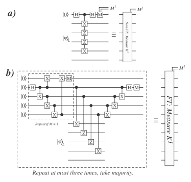
Where and are the Pauli and operators, is the 2 2 identity matrix, and the tensor product is implied. Error correction using stabiliser codes is straightforward shor1 ; Nielsen , each of the four generators are measured [Fig. 3(a)] either sequentially using a single ancilla, or simultaneously using four ancilla. Each of the sixteen possible four-bit results represent one of the correctable single qubit errors, as well as the case where no error occured. At a minimum, fault-tolerant measurement of the stabilisers requires a four qubit GHZ state as an ancilla block [Fig. 3(b)]. Additionally, a fifth qubit is used to verify the GHZ state against possible errors which can subsequently propagate to the data block. Therefore the minimum number of ions in a single trap needed for logical encoding and correction is six, while a total of ten ions are needed to employ full fault-tolerant correction sequentially.
The interaction between logical qubits in separate nodes is mediated by interface ions entangled into Bell pairs by any one of a number of methods CCGZ1999 ; PHBK1999 ; BKPV1999 ; BPH2003 . It has been shown that some two-qubit gates can be performed using Bell pairs via LOCC Gottesman1998 ; VC2004 ; DBMM2004 ; DMMMKM2006 . A large class of quantum codes, known as Calderbank-Shor-Steane (CSS) codes, allow logical controlled- (CNOT) and controlled- (CZ) gates to be applied block-wise between two data blocks, which are also inherently fault-tolerant. However, the [[5,1,3]] quantum code is not a CSS code and block-wise CNOT or CZ gates are not possible. This also means that the more rapid method of error correction introduced by Steane steane , requiring a larger ancilla block, will not work with the [[5,1,3]] code. However, a logical CNOT or CZ interaction between two logical blocks of data can be performed for any code that allows for block-wise single-qubit bit and/or phase operations using fewer interface qubits than the standard block-wise approach. This method, first proposed in leung and devitt uses the same basic element as error correction, namely operator measurements.
A CZ gate between two qubits can be written in terms of operators on an arbitrary two qubit state as,
| (2) |
To achieve this transformation on an arbitrary two-qubit state, we append an ancilla qubit prepared in the state , and measure the operators and over the three qubit system. After these measurements, and assuming that the qubits are always projected to a eigenstate of these operators (otherwise local corrections can be applied), the final state is given by
| (3) |
Since the Pauli operators and anti-commute and that and , the state can be re-written as,
| (4) |
after which the ancilla is then measured in the computational basis. If the measurement result is , is projected to CZ, otherwise it is projected to upon which a local correction is then applied.
We use the above method to perform a logical CZ across two nodes. A single physical Bell state is prepared between two nodes each containing a logical qubit. Each half of the Bell state is used as a control qubit on the respective data block of an encoded qubit. For example, to measure the logical operator across two logical blocks, local CZ gates are applied between each Bell pair qubit and the five ions representing the single logical qubit in each node. For a general state of two logical qubits , the transformation is
| (5) |
where is as in Eq.1, a logical phase gate for the [[5,1,3]] code. A local Hadamard gate is applied to both interface qubits, leading to the state,
| (6) |
Measuring the parity of interface qubits projects the data qubits into a eigenstate of for an even/odd parity result, hence performing the required measurement.
Measuring an appropriate sequence of operators will enact a logical controlled phase rotation across two nodes. To perform the full CZ gate, an ancilla is needed which is finally measured in the computational basis. This ancilla does not need to be a fully encoded logical qubit in its own trap, it can just as easily be a single ion contained in either the control or target trap. However, to maintain fault-tolerance this ancilla qubit should be encoded. By using operator measurements between traps. inter-logical operations can be performed directly on the [[5,1,3]] encoded data using only one interface qubit per trap.
Localizing a single logical qubit plus appropriate ancilla ions for local error correction has several advantages. Intra-trap operations have been demonstrated on up to eight ions BlattEA2005 so local operations and error correction should suffer minimal overhead. Probabilistic entanglement generation CCGZ1999 ; PHBK1999 ; BKPV1999 ; BPH2003 does not pose a problem for inter-node operations as local error correction can preserve coherence between the generation of entangled links. This is substantially more advantageous than other highly distributed schemes DBMM2004 where all ions interact via these non-local linkages which would be highly susceptible to memory errors while waiting for non-local links to be established. If required, local control permits the use of purification protocols in order to increase inter-trap gate fidelity DB2003 . Also, by structuring all inter-logical operations such that they are mediated by entangled links, larger trap structures, for example the CCD design of Kielpinski et. al. KMW2002 , need only be designed, and optimized, for local error correction.
From an experimental standpoint, the preparation of a logically encoded Bell pair does not require the operator CZ gate in full. If the initial state is , the measurement of the operator is sufficient to produce the state . Hence experimental demonstration of encoded Bell state preparation does not need the third ancilla qubit required by the operator CZ gate.
Without maintaining fault-tolerance, we only require five (data block) one (ancilla) one (interface) ions per trap to implement the protocol. Fig. 4 shows the complete quantum circuit required to implement the state preparation non-fault-tolerantly, assuming that full local error correction cycles are performed in the time required to prepare the inter-trap Bell link.
II.1.2 Fault-Tolerant encoded state preparation.
This general method for preparing a distributed, encoded Bell state is not fault-tolerant. Utilizing a single qubit for correction allows errors to cascade into the data block. Also, the Bell pair interface can induce logical errors if it is not prepared correctly.
Maintaining fault-tolerance for local error correction is fairly straightforward shor ; Nielsen . The stabilizers for the [[5,1,3]] code have a maximum weight of four, hence the ancilla ion used for correction is replaced with five ions, four of which are prepared in the entangled state , after which the fifth is used to verify the ancilla state against errors that can propagate to the data block. If verification fails, the ancilla block is reset and re-prepared. Once the state is verified, each of the four ancilla ions are coupled to the data block, with local CNOT and Hadamard gates (depending on the stabiliser structure) and measured to determine the syndrome. To protect against errors, occurring or propagating to the ancilla block, the syndrome is measured multiple times. At least two syndrome measurements are made, if they disagree a third syndrome is measured and a majority vote taken [Fig. 3(b)]. We adapt this general method to operator measurement gates between traps.
Errors in the Bell link between node, either during preparation or during operation, can lead to multiple errors propagating to the data blocks. For fault-tolerance we again use several ancillas, thereby ensuring that only one ancilla qubit interacts with one qubit within the data block. Measuring the operator , where , requires a Bell link between the two nodes and the ability to perform CNOT or CZ gates between each qubit in the Bell pair and their respective data block. If an error occurs on the Bell pair then this can propagate to possibly all of the qubits within one of the nodes. If this occurs, the single qubit error will induce a logical error. To counter this, we introduce several more ancilla qubits into each node and verify the interface qubit state before coupling ions to the data block.

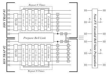
The required circuit needed to prepare a sufficient interface ancilla for the [[5,1,3]] code is shown in Fig 5. We use two Bell pairs and two additional ancilla qubits in each node that are coupled to the original Bell pair through CNOT gates. After preparation, the ancilla blocks of the two nodes are in the state,
| (7) |
The subscripts 1 and 2 represent the three ancilla qubits within each node, while the subscript represents a second Bell link between the two nodes used for ancilla verification. Now a CNOT gate is performed between the last qubit in each node and the verification Bell state. If no errors have occurred then the CNOT operations will leave the verification Bell pair invariant. Considering all the possible single error locations during the preparation of the ancilla state we find the following unique states are possible.
Where . The verification qubits are measured in the computational basis and if an even parity result is obtained, then the ancilla state is verified, otherwise either the ancilla or verification qubits have experienced a single error and we repeat the preparation.
The inclusion of the second Bell link between two nodes and the additional ancillas allows the verification of the ancilla state prior to coupling it to the data qubits, protecting the ancilla state from a single error. Phase errors in the ancilla block result in an incorrect determination regarding which eigenstate the data qubits are projected to. To protect against this, the operator is measured two to three times and a majority vote taken. At each stage, error correction can be continuously performed on each data block while the interface ancilla block is prepared and verified.
In Section II.1.1 we showed how the Bell link can allow the measurement of a given Hermitian operator. This required performing a controlled operation from the Bell link qubits to each of the data qubits. For the [[5,1,3]] code, this allows for a logical and/or operator measurement since these logical operations can be performed block-wise. To maintain Fault-Tolerance, this would require five ancilla qubits in each node connected to the Bell pair. However we can reduce this to three in each node by exploiting the stabiliser structure of the [[5,1,3]] code.
Any given logical state encoded with the [[5,1,3]] code is stabilised by the operators to . Therefore , . If a logical () operation is performed on the state, it is not necessary to apply five single qubit () gates, but we can redefine the logical operators in terms of the stabilisers. Consider the first stabiliser . Then,
| (9) |
therfore only three operators, hence four ancilla qubits, are required for the interface block, instead of five.
The total number of ions in each trap for full fault-tolerant local correction and coupling between the traps is fourteen. Five ancilla ions are needed for local fault-tolerant error correction of the five ion logical qubits, while four ions are needed as the interface ancilla block including two non-local Bell links, one to actually link the traps and one to verify the ancilla block. The total number of qubits needed for this scheme and the number of non-local Bell links for a general quantum code is significantly less depending on the size of the code used. For a general, CSS, qubit code correcting a single error, and assuming that no purification protocols are used, Bell links are required to perform a block-wise CZ gate in one time step. In contrast, this scheme only requires two Bell links (regardless of the code size) to perform a CZ gate in several time steps. In between each step, local error correction can be performed to protect against memory errors.
II.2 Extending the scheme to larger architectures
The above scheme of preparing a non-local encoded Bell state between two separate nodes can easily be extended to a much larger distributed system. Each node would be designed to house a single logical qubit, or several logical qubits for a general [[,,]] code with . If multiple concatenation levels are warranted, then the node system would also have the requisite number of qubits and routing system to allow full Fault-Tolerant error correction at all levels. The inter-logical operations, at the highest level of encoding are then performed using the non-local Bell links and the operator measurement protocol. For a multiply concatenated () level qubit, the operator measurement formalism can be extended in a straightforward manner.
For all CSS codes, block-wise and operations are possible. Hence to measure these operators across two nodes at the level of encoding, a CZ or CNOT gate is performed between each half of a Bell link pair of qubits and all of the physical qubits in the two separately encoded nodes. Fault-tolerance would require a similar ancilla system as that used in the [[5,1,3]] example. Instead of using two Bell links and four ancilla qubits per trap, the total number of ancillas will be equal to
| (10) |
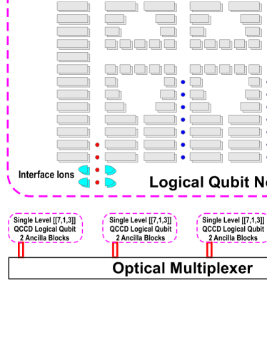
where is the concatenation level and is the minimum weight of the qubit operation that invokes a blockwise logical operation on the qubit (if multiple qubits are encoded within a single node). The number of Bell links required between nodes remains constant at two, unless a quantum code is employed that encodes multiple logical qubits. In this case inter-logical operations between states located in different nodes will require two Bell links for each pair of qubit interactions between nodes. Figure 6 shows an example structure for a distributed computer using the CCD trap design. Each CCD chip is designed exclusively for a single logical qubit encoded with the [[7,1,3]] Steane code. Each chip houses seven data qubits, an additional 28 ancilla qubits which would allow for the simultaneous preparation and verification of two separate ancilla blocks using the rapid method of Steane steane , and the four interface qubits which are required for fault-tolerant operator measurements using the Steane code. Each chip is manufactured and characterized separately and would be plugged in to the optical multiplexer, linking it to the rest of the computer.
Within a larger architecture, the logical qubits needed for a given quantum algorithm are interspersed with logically encoded ancilla traps that are then used to perform logical CZ gates using the methods described in Section II.1.1.
III Node Design
To summarize the architecture, each node should satisfy the key requirements:
-
•
A sufficient number of long lived physical qubits for an error corrected logical qubit.
-
•
An additional number of ancilla qubits for error correction and operator measurements. Measurement of these ancilla should be fast and reliable. The absolute coherence time of these ancilla may be traded against fast operations.
-
•
A qubit which can be entangled with its counterpart in another node. This process can be probabilistic but heralded.
-
•
Fast and reliable single and two-qubit operations within the node for single logical qubit operations, error correction, operator measurements, and entanglement purification.
If multiple Bell links are required with a single node, the state of the interface qubit can be swapped to an ancilla and the interface qubit re-entangled. Of course, multiple interface qubits would allow for parallel entangling operations but are not strictly necessary. Entanglement purification may be required to increase the fidelity of the entangled links between traps. Nested entanglement pumping DBCZ1999 reduces the number of ancilla required for high fidelity Bell pairs.
Segmentation of a linear trap could be used to isolate the interface ion from the rest of the trap until required. By suitable geometry, the interface region would not impinge on intra-trap operation, either by phonon coupling or photon scattering. When entanglement is needed, the trap potentials are rearranged so that an ancilla ion could be placed into a common mode with the interface ion and quantum state transfer performed, afterwards which the ancilla would be brought back to the rest of the ions for further processing.
Though we have primarily considered a linear Paul trap as a node, one could replace it with any other small qubit system as long as the above requirements are met, e.g. a CCD trap with an optical interface region as in Section II.2. The Penning trap COCWST2006 has also been suggested as a candidate for quantum computation, with hundreds or thousands of ions in a single two-dimensional Coulomb crystal DBHHS1998 ; PC2006 and two-qubit gates via transverse phonon modes ZMD2006 . The large number of physical qubits would allow larger code words protecting against multiple errors and/or optimised for different error models. However, the rotation of the crystal would complicate ion addressing 222This could be achieved in principle, for instance, with a rotating dove prism synchronised with the crystal rotation locked to an external driving frequency HBMI1998 . and would restrict strong cavity coupling to the central ion 333In such a system, the interface qubit would increasingly be the bottleneck, restricting inter-node operation, unless scheduling could restrict operations within qubits within a single node whereever possible..
Within each node, the physical qubits play different roles opening up the possibility of optimization of their separate properties. The data qubits require long coherence times, whilst we may want to optimise the ancilla qubits for fast operations and measurement. The interface qubit should have suitable optical properties for the entanglement generation procedure. In a Paul ion trap, different ionic species could be utilized and loaded in order by frequency selective ionization BBHPEN2006 . The use of heavier ions (such as ) for data storage may reduce gate errors due to spontaneous decay from intermediate metastable states WinelandEA2003 , or else direct microwave driving of hyperfine transitions could eliminate this entirely WB2003 . Lighter ions could be used as ancilla in order to lower the mass of the ion string and hence raise the axial phonon frequencies aiding cooling and two-qubit gate times.
To reduce the number of ions in each node, the use of multiple levels in the ground hyperfine manifold to encode multiple qubits could be considered ARDA . Since measurement is likely to distinguish the state of all the encoded qubits of an ion, this method may not be suitable for data qubits, but is not necessarily a drawback for use for ancilla qubits which en bloc are measured and initialized repeatedly.
IV Conclusion
We have proposed the use of entanglement to directly implement non-local operations between separately housed logical qubits. These ideas may also be applicable to other physical quantum computing implementations which satisify the requirements in Section III 444For example, ion traps connected via superconducting elements TRBZ2004 , superconducting qubits connected via microstriplines and polar molecules RDDLSZ2006 ; ADDLMRSZ2006 or solid state spin qubits coupled via superconducting cavity QED BI2006 .. The entanglement is created by a point-to-point process which reduces routing difficulties and enables parallel operation. Logical operations via operator measurements require minimal entangled resources compared to a directly teleported sequence of block-wise gates but still retains fault tolerance. By keeping data local to a single node, the node can be of comparatively simple design and size, optimized for local high fidelity operations. The technique should be able to be generalized to multi-qubit operations utilizing multi-partite entangled states and may serve as the basis for a full scalable quantum computing architecture. A proof of principle demonstration with two traps containing seven or eight ions and an optical interface each is within the reach of current experiment KLHLW2003 ; BlattEA2005 . Even simpler to demonstrate are operator measurement gates, the optical interface could be omitted and a gate performed between two three-qubit encoded (single X or Z-error) logical qubits coupled via a single Bell pair. Such a distributed architecture is a strong alternative to monolithic designs.
Acknowledgements.
DKLO acknowledges the support of the Cambridge-MIT Institute Quantum Information Initiative, EU grants RESQ (IST-2001-37559) and TOPQIP (IST-2001-39215), EPSRC QIP IRC (UK), and Sidney Sussex College, Cambridge. SJD acknowledges the support of the Rae & Edith Bennett Travelling Scholarship. LH and SJD are supported in part by the Australian Research Council, the Australian Government and the US National Security Agency (NSA), Advanced Research and Development Activity (ARDA), and the Army Research Office (ARO) under contract number W911NF-04-1-0290. The authors would also like to thank D. Segal for enlightening discussions.References
- (1) Quantum Computation and Information, M.A. Nielsen and I.L. Chuang, Cambridge University Press, 2000.
- (2) D. Kielpinski, C. Monroe, and D. J. Wineland, Nature 417, 709 (2002)
- (3) T. S. Metodi, D. Thaker, A. W. Cross, F. T. Chong, I. L. Chuang Proc. SPIE 5815, Quant. Inf. & Comp. III, E. J. Donkor, A. R. Pirich, H. E. Brandt, Eds, May 2005, pp. 91-102
- (4) J. M. Taylor, H.-A. Engel, W. Dür, A. Yacoby, C. M. Marcus, P. Zoller and M. D. Lukin, Nature Phys. 1, 177-183 (2005)
- (5) L.C.L. Hollenberg, A.D. Greentree, A.G. Fowler, C.J. Wellard, quant-ph/0506198. (To appear in PRB) (2005)
- (6) S. J. Devitt, A. D. Greentree, L. C. L. Hollenberg, quant-ph/0511084
- (7) D. Leibfried, E. Knill, S. Seidelin, J. Britton, R. B. Blakestad, J. Chiaverini, D. B. Hume, W. M. Itano, J. D. Jost, C. Langer, R. Ozeri, R. Reichle and D. J. Wineland Nature 438, 639 (2005)
- (8) H. Häffner, W. Hänsel, C. F. Roos, J. Benhelm, D. Chek-al-kar, M. Chwalla, T. Körber, U. D. Rapol, M. Riebe, P. O. Schmidt, C. Becher, O. Gühne, W. Dür and R. Blatt, Nature 438, 643 (2005)
- (9) A. M. Steane, quant-ph/0412165
- (10) A. M. Steane, D. M. Lucas, Fortschritte der Physik 48, 839 (2000)
- (11) M. Keller, B. Lange, K. Hayasaka, W. Lange, and H. Walther, Appl. Phys. B 76, 125 (2003)
- (12) L.-M. Duan, B. B. Blinov, D. L. Moehring, C. Monroe, Quant. Inf. & Comp. 4, 165 (2004).
- (13) L.-M. Duan, M. J. Madsen, D. L. Moehring, P. Maunz, R. N. Kohn Jr., C. Monroe, quant-ph/0603285
- (14) J. I. Cirac, P. Zoller, H. J. Kimble, and H. Mabuchi, Phys. Rev. Lett. 78, 3221 (1997)
- (15) T. Pellizari, quant-ph/9707001
- (16) S. J. van Enk, H. J. Kimble, J. I. Cirac, and P. Zoller, Phys. Rev. A 59, 2659 (1999)
- (17) T. C. Ralph, A. J. F. Hayes, A. Gilchrist, quant-ph/0501184
- (18) Peter P. Rohde, Timothy C. Ralph, William J. Munro, quant-ph/0603130
- (19) W. Dür and H. J. Briegel, Phys. Rev. Lett. 90, 067901 (2003)
- (20) A.G. Fowler, quant-ph/0411206.
- (21) R. Laflamme, C. Miquel, J. P. Paz, and W. H. Zurek, Phys. Rev. Lett. 77, 198 (1996)
- (22) D.P. DiVincenzo and P.W. Shor, Phys. Rev. Lett. 77, 3260 (1996)
- (23) D.Gottesman quant-ph/9705052.
- (24) C. Cabrillo, J. I. Cirac, P. García-Fernández, and P. Zoller, Phys. Rev. A 59, 1025 (1999)
- (25) M. B. Plenio, S. F. Huelga, A. Beige, and P. L. Knight, Phys. Rev. A 59, 2468 (1999)
- (26) S. Bose, P. L. Knight, M. B. Plenio, and V. Vedral, Phys. Rev. Lett. 83, 5158 (1999)
- (27) Daniel E. Browne, Martin B. Plenio, and Susana F. Huelga, Phys. Rev. Lett. 91, 067901 (2003)
- (28) F. Verstraete, J.I. Cirac, Phys. Rev. A 70, 060302(R) (2004)
- (29) Daniel Gottesman, quant-ph/9807006
- (30) A.M. Steane, quant-ph/0202039, (2002).
- (31) P. Aliferis and D.W. Leung, Phys. Rev. A. 70, 062314 (2004).
- (32) S.J. Devitt, A.D. Greentree and L.C.L. Hollenberg, quant-ph/0511084, (2005).
- (33) P. W. Shor, 37th Annual Symposium on Foundations of Computer Science (FOCS ’96) p. 56, (1996)
- (34) R. Raussendorf, H.-J. Briegel, Phys. Rev. Lett. 86, 5188 (2001)
- (35) S. C. Benjamin, D. E. Browne, J. Fitzsimons, J. J. L. Morton, quant-ph/0509209
- (36) W. Dür, H.-J. Briegel, J. I. Cirac, and P. Zoller, Phys. Rev. A 59, 169 (1999)
- (37) J. R. Castrejón-Pita, H. Ohadi, D. R. Crick, D. F. A Winters, D. M. Segal, and R. C. Thompson, quant-ph/0603195, J. Mod. Opt. Forthcoming
- (38) M. Drewsen, C. Broderson, L. Hornekær, J. S. Hangst, and J. P. Schifffer, Phys. Rev. Lett. 81, 2878 (1998)
- (39) D. Porras and J. I. Cirac, quant-ph/0601148
- (40) Shi-Liang Zhu, C. Monroe, L.-M. Duan, quant-ph/0601159
- (41) X.-P. Huang, J. J. Bollinger, T. B. Mitchell, and Wayne M. Itano, Phys. Rev. Lett. 80, 73 (1998)
- (42) D. J. Wineland, M. Barrett, J. Britton, J. Chiaverini, B. DeMarco, W. M. Itano, B. Jelenković, C. Langer, D. Leibfried, V. Meyer, T. Rosenband, T. Schätz, Phil. Trans. Roy. Soc. A 361, 1349 (2003)
- (43) C. Balzer, A. Braun, T. Hannemann, C. Paape, M. Ettler, W. Neuhauser, C. Wunderlich, quant-ph/0602044
- (44) C. Wunderlich, C. Balzer, Adavnces in atomic, molecular and optical physics 49, 293, (2003)
- (45) ARDA Quantum computation Roadmap, Section 6.2: Ion Trap Approaches to Quantum Information Processingand Quantum Computing
- (46) L. Tian, P. Rabl, R. Blatt, and P. Zoller, Phys. Rev. Lett. 92, 247902 (2004)
- (47) P. Rabl, D. DeMille, J. M. Doyle, M. D. Lukin, R. J. Schoelkopf, P. Zoller, quant-ph/0604140
- (48) A. Andre, D. DeMille, J. M. Doyle, M. D. Lukin, S. E. Maxwell, P. Rabl, R. Schoelkopf, P. Zoller, quant-ph/0605201
- (49) G. Burkard, A. Imamoglu, cond-mat/0603119