0.9in0.9in0.6in0.8in
Quantum Circuit Simplification and Level Compaction††thanks:
Copyright IEEE. Reprinted from IEEE Transactions on
Computer-Aided Design of Integrated Circuits and Systems, 27(3):436–444, March 2008.
This material is posted here with permission of the IEEE. Internal or
personal use of this material is permitted. However, permission to
reprint/republish this material for advertising or promotional purposes or
for creating new collective works for resale or redistribution must be
obtained from the IEEE by writing to
pubs-permissions@ieee.org.
By choosing to view this document, you agree to all provisions of the
copyright laws protecting it.
Abstract
Quantum circuits are time dependent diagrams describing the process of quantum computation. Usually, a quantum algorithm must be mapped into a quantum circuit. Optimal synthesis of quantum circuits is intractable and heuristic methods must be employed. With the use of heuristics, the optimality of circuits is no longer guaranteed. In this paper, we consider a local optimization technique based on templates to simplify and reduce the depth of non-optimal quantum circuits. We present and analyze templates in the general case, and provide particular details for the circuits composed of NOT, CNOT and controlled--of-NOT gates. We apply templates to optimize various common circuits implementing multiple control Toffoli gates and quantum Boolean arithmetic circuits. We also show how templates can be used to compact the number of levels of a quantum circuit. The runtime of our implementation is small while the reduction in number of quantum gates and number of levels is significant.
1 Introduction
Research in quantum circuit synthesis is motivated by the growing interest in quantum computation [19] and advances in experimental implementations [4, 7, 8, 25]. In realistic devices, experimental errors and decoherence introduce errors during computation. Therefore, to obtain a robust implementation, it is imperative to reduce the number of gates and the overall running time of an algorithm. The latter can be done by parallelizing (compacting levels) the circuit as much as possible.
Even for circuits involving only few variables, it is at present intractable to find an optimal implementation. Thus a number of heuristic synthesis methods have emerged. Application of these methods usually results in a non-optimal circuit, that can be simplified with local optimization techniques. Additionally, some quantum circuits for important classes of functions, such as adders and modular exponentiation, were created and compacted in an ad-hoc manner [5, 17].
Local optimization has only recently been considered as a possible tool for the gate count reduction in quantum [13] and reversible (quantum Boolean) circuits [10]. Some quantum circuit identities that could be used for circuit simplification can be found in [19]. While these provide several rewriting rules with no ready to use algorithm for their application, there is clearly a benefit in a systematic approach through the use of templates discussed in this paper. A somewhat different approach for local optimization of reversible NOT-CNOT-Toffoli circuits was applied for the simplification of random reversible circuits in [22]. That approach and our template method are difficult to compare as they have been applied to different types of circuits with different metrics for the circuit cost.
So far, CAD tool designers spent little effort on minimizing the number of logic levels in quantum circuits. However, this allows a shorter running time as it results in a parallelization of the algorithm. More importantly, in the popular quantum error model where errors appear randomly with time, a parallel circuit helps to reduce the errors. For instance, it may be possible to use smaller number of error correction code concatenations (each of which is a very expensive operation, requiring to at least triple the number of physical qubits [19]) if the circuit is well parallelized. To the best of our knowledge, all of the presently existing quantum circuits were at best compacted in an ad-hoc fashion. In our work we automate level compaction through the use of templates.
Methods based on templates have been considered for Toffoli reversible network simplification [14]. In this paper, we revisit the definition of templates and show how they can be applied in the quantum case as a systematic basis for the quantum circuit simplification and level compaction.
The paper111A preliminary version of this work was presented at DATE-2005 conference. This paper discusses circuit parallelization, reports the improved results based on a new and significantly more efficient implementation, includes extensive testing results, as well as certain new discussions. is organized as follows. We start with a brief overview of the necessary background in Section 2. In Section 3 we define the templates and discuss some of their properties. We present a method to identify the templates and describe two algorithms, one to reduce the cost and the other to reduce the number of logic levels of quantum circuits in Section 4. We next choose a specific quantum gate library, and illustrate effectiveness of the above approach. Section 5 presents a set of small quantum templates for NOT, CNOT and controlled--of-NOT gates and illustrates the algorithms. The benchmark results presented in Section 6 are divided into two parts. We first optimize quantum implementations of the multiple control Toffoli gates (including multiple control Toffoli gates with negative controls) and then consider optimization of some NOT-CNOT-Toffoli circuits available through existing relevant literature. Discussion of future work and concluding remarks are found in Sections 7 and 8.
2 Background
We present a short review of the basic concepts of quantum computation necessary for this paper. An in-depth coverage can be found in [19].
The state of a single qubit is a linear combination (also written as a vector ) in the basis , where and are complex numbers called the amplitudes, and . Real numbers and represent the probabilities and of reading the logic states and upon measurement. The state of a quantum system with qubits is given by an element of the tensor product of the single state spaces and can be represented as a normalized vector of length , called the state vector. Quantum system evolution allows changes of the state vector through its multiplication by unitary matrices called gates.
The above models how a transformation can be performed, but does not indicate how to identify the unitary operations that compose the transformation or how to implement them. Efficiency of the physical implementation depends on the system’s Hamiltonian, and the details of different systems (and associated gate costs) are not a focus of this paper. Typically, certain primitive gates are used as elementary building blocks [19, 2]. Among these are:
-
•
NOT () and CNOT () gates, where and is addition modulo 2;
-
•
Hadamard gate defined by ;
-
•
controlled-V gate that depending on the value on its control qubit changes the value on the target qubit using the transformation given by the matrix ;
-
•
controlled- that depending on the value of its control qubit changes the value on the target qubit using the transformation ;
-
•
rotation gates , .
We shall write to denote the gate implementing the inverse function of the function realized by gate . In context, we will use to mean a gate or the transformation matrix for that gate. The circuit diagrams are built in the popular notations, such as those used in [19]. In short, horizontal “wires” represent a single qubit each; the time in the circuit diagrams is propagated from left to right; (positive) gate controls are depicted with ; targets appear as for NOT and CNOT gates, V for controlled- gate, and V+ for controlled- gate with vertical lines joining control(s) of a gate with its target.
The principle of the optimization method is to associate a cost to each of these elementary gates and lower the overall circuit cost by reducing the number of high cost gates. The cost definition must reflect how difficult it is to implement the gate is and therefore will depend on the details of the physical device considered to implement the circuit. For example, for NMR techniques the cost of the gate must take into account the number of rf-pulses as well as the duration of the interaction periods necessary to implement the gate [4]. In a setting guided by the Ising type Hamiltonian in a weak coupling regime (such as liquid NMR [4] and superconductors [6]) a controlled- and its complex conjugate must be associated with approximately half the cost of a CNOT gate each. Thus, controlled- and controlled- are not at all complex gates. Two qubit gate implementation costs in any given Hamiltonian can be found using the technique discussed in [26].
The Toffoli gate [24] and its generalization with more than two controls serve as a good basis for synthesis purposes. Indeed, every reversible (quantum Boolean) function can be realized as a cascade of multiple control Toffoli gates [2, 14]. The multiple control Toffoli gate flips the target bit if the control bits are in a given Boolean state. Unfortunately, multiple control Toffoli gates (including the original Toffoli gate [24]) are not simple transformations in quantum technologies. They require a number of elementary quantum operations and Toffoli gates with a large number of controls can be quite costly [2]. However, they can be implemented using circuits composed with 3-qubit Toffoli gates [2]. Finally, the 3-qubit Toffoli gate can be constructed from a set of gates that includes the NOT, CNOT, controlled- and controlled-. We therefore consider all these gates in Section 5 when we search for templates to simplify the best known quantum circuits implementing large Toffoli gates and reversible functions. In addition, any unitary can be synthesized as a generic quantum circuit through exploring the properties of matrix decompositions [2, 21, 18]. We do not consider those circuits here, but point out that our circuit simplification techniques are applicable in any of the above cases.
3 Templates: definition
To decrease the cost of a circuit, the basic idea is to replace a sub-circuit with an equivalent one that has lower cost. We will call this procedure the application of a rewriting rule. Some problems arise with this technique:
-
•
In general, even for simple circuits, if rotation gates with any parameter are allowed the number of possible rewriting rules is infinite.
-
•
Equivalent circuits with same cost might require different sets of rewriting rules to be simplified.
-
•
A sub-circuit may be rewritten in another form having the same cost, but this second form could allow extra-simplifications on the circuit using other rewriting rules.
One of the problems arising from these considerations is to minimize the number of rewriting rules by keeping only “essential” ones. To address these issues we introduce the notion of templates that will be applicable to all quantum gate libraries and discuss the algorithms for quantum gate reduction and level compaction.
Definition: A size template is a sequence of gates that implements the identity operator and that satisfies the following constraint: any template of size must be independent of all templates of smaller or equal size, i.e. for a given template of size no application of any set of templates of smaller or equal size can decrease the number of gates in or make it equal to another template.
A template can be seen as a generalization of the rewriting rules, since rewriting rules can be derived from it. For example, forward application of the template allows us to find a rewriting rule of the form , where . Similarly, backward application of the template is a rewriting rule of the form , where .
Template application requires that the inverse of each gate be available. Clearly, templates are a more compact way of representing non redundant rewriting rules as it is capable of storing up to rewriting rules.
See Appendix for a proof of the effect of the forward and backward applications of templates.
4 Templates: application
In this section we present a method to find and classify the templates and introduce two algorithms using them. One is an algorithm for quantum cost reduction and the other for quantum circuit level compaction, both based on the notion of the templates.
4.1 Template identification
First we find all templates of the form (length 2), which we call gate-inverse rules. This is straightforward, since every self-inverse gate forms the template and every pair of gates and , where forms one template of the form .
Subsequent templates are found by identifying increasingly longer sequences of gates that realize the identity function and that can not be reduced by other available templates.
Templates of the form (length 4) with and applied for parameter result in construction of the rewriting rules and . That is, they define the conditions under which two gates commute. We call such templates moving rules and apply them to move gates to form matches leading to reduction via other templates.
For applications, we suggest seeking a complete classification of the templates of small size and then supplementing those by a set of templates that appear to be useful when a specific synthesis procedure is applied. For example, if a synthesis procedure (or the circuit types one considers) tends to use a specific type of sub-circuit of cost which is neither optimal (assume an optimal cost of ) nor can be simplified by a small size complete set of templates, a template with total cost can be created (followed by a generalization process when and if needed). In this paper, we do not construct any of these supplementary type templates, since we apply templates to the circuits from different authors obtained from different synthesis procedures.
4.2 Cost reduction
In this section, we present an algorithm to reduce generic
quantum circuit cost using the templates. To apply the algorithms to
a specific physical implementation, we only need to
choose a relevant cost definition.
Input: A quantum circuit specification, i.e. a
sequence of gates .
Output: A quantum circuit computing the same
function as the input circuit, but having a possibly lesser
cost.
Algorithm:
-
1.
Let be the start gate in the circuit for a potential template match. Initially .
-
2.
We attempt to match the templates in order of size (excluding the moving rules). The attempt to match to a size template proceeds as follows:
-
(a)
Forward matching: Apply the moving rules to arrange the gates preceding to be able to match them with the given size template. At this step we determine pair such that . When such a and are found, gates can be replaced by the sequence . Substitution is done if it is beneficial from the point of view of the overall circuit cost reduction.
-
(b)
Backward matching: To backward match a size template, the same procedure applies with the following matching condition: . Then, gates can be replaced by the sequence . The decision to replace or not is based on a chosen circuit cost metric.
-
(a)
-
3.
We propagate this procedure through the circuit:
The gate replacement at step 2 is performed when it is beneficial to do such replacement i.e. when the total circuit cost is reduced. This imposes extra constraints on the parameter depending on the exact cost definition. For instance, with simple gate count cost metric, must be greater than . If many pairs are found, the one associated to the biggest cost reduction is chosen for the gate substitution. However, even if the total cost after template application stays the same (for simple gate count cost metric this means applying an even size template by replacing its half with another half, i.e. for even and ) the substitution can be beneficial as the new circuit arrangement may allow other cost reducing template applications. We take this into account by allowing such “cost retaining” template applications as long as ( is value of the subscript of ), with the initially set to . After each cost retaining template application the is set to the current value, and after each cost reducing template application the is set back to . This guarantees that the cost reduction algorithm will not run into an infinite loop while allowing cost retaining template application.
In Section 5 we illustrate how the templates are applied to reduce the gate count.
4.3 Level compaction
We next suggest a greedy algorithm
for quantum circuit level compaction employing templates. A level is
defined as a sub-sequence of commuting gates that can be applied in
parallel. Level compaction
helps to increase the parallelization of the circuit implementation and
therefore not only optimizes the runtime of the circuit, but also helps to
decrease the decoherence effects by shortening the overall execution
time222For instance, a liquid NMR circuit with a high degree of
parallelization of single qubit rotations and ZZ-gates will be
singnificantly shorter than its unparallelized version. Indeed, single qubit
rotations on homonuclear spins are usually implemented by selective
soft pulses sent sequentially to act on each spin. Nevertheless, if
we want to act on all homonuclear spins in parallel, it is possible to
use a single broad-band short pulse [4]. As
for heteronuclear spins, modern spectrometers have several channels that
can be used simultaneously. Therefore, one can rotate heteronuclear
spins in parallel by pulsing on them in parallel.
More importantly, in a typical NMR system, the main time consuming
gates are the interaction gates (ZZ gates). Because all the couplings
are always on in a molecule, ZZ-gates naturally occur in parallel in
the circuit. To apply a ZZ gate to a given pair of qubits, one needs to
use refocussing techniques [4] involving pulses
and delays to cancel all the ZZ-interactions but the desired one.
Therefore, in most of the cases, regrouping the ZZ-gates will allow to
optimize the refocussing scheme and reduce the overall number of
required delays. In particular, refocussing scheme exists for any subset
of non-intersecting gates defined as a single logic level in this paper [11]..
For simplicity of the algorithm description, we assume
that all gates have the same duration, therefore, the execution time
of a level is equal to a single gate duration. We also assume that
neighboring gates operating on disjoint qubit
subsets can always be applied in parallel, which is a common
assumption for quantum technologies.
Input: A quantum circuit specification, i.e.
a cascade of gates .
Output: A re-organized circuit with possibly fewer levels
computing the same function as the input circuit.
Algorithm: The principle is to assign a specific level to each gate.
-
1.
Initially, all gates in the circuit have undefined level, and we define as an empty set.
-
2.
Consider the leftmost gate not yet assigned a level. Assign it level .
-
3.
Until each gate right of is considered:
-
(a)
If gate does not share common qubits with any of the gates in level and gate can be moved left (using the moving rules) until it is adjacent to the leftmost gate with level and then assign gate level .
-
(b)
If it is not possible to move gate as just described, apply templates using the algorithm described above using as the start gate and considering only those gates whose level has not been assigned yet. Only templates with an even number of gates are applied and only substitutions of for gates are made. Such substitution may allow a gate to subsequently (possibly with movement) to be assigned to level .
-
(a)
- 4.
At this stage of development, the level compaction algorithm is greedy. We expect that it can likely be improved. However, our tests have shown that its current performance already improves relevant quantum circuits.
5 Quantum NCV templates
We now present a set of quantum templates based on the NOT, CNOT and controlled--of-NOT (NCV) gates. It contains:
-
•
The gate-inverse rules: NOT and CNOT are self-inverses and controlled- and controlled- are the inverses of each other.
-
•
The moving rule (replace with ): assuming gate has control set ( is an empty set in the case of an uncontrolled gate) and target and gate has control set and target , these two gates form a moving rule if, and only if, and .
-
•
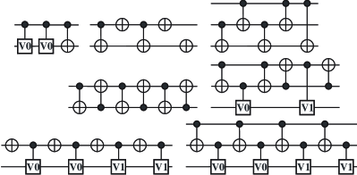
Larger templates: all other templates that we have identified are shown in Figure 1, where (alternatively ) is substituted for all occurrences of and (alternatively ) is substituted for all occurrences of , i.e. the substitution is consistent and distinct for and . The templates reported here were found by inspection. We are currently developing a program to find larger templates systematically and to verify completeness of the current set.
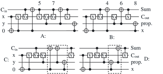
To illustrate how templates are applied, consider the quantum circuit for the 3-input full adder with 10 gates from [9]. The circuit is built on four qubits as the 3-input adder must be extended to a 4-variable reversible function. Note that the original circuit presented in [9] gives 1111 as output for input pattern 0100 instead of the expected 1011. The circuit shown in Figure 2A corrects this.
In the circuit in Figure 2A, gates 5 and 7 (counting from the left) can be moved together and form a gate-inverse pair. We move them together and delete them by applying the gate-inverse rule. This results in the circuit illustrated in Figure 2B.
Next, we notice that gates 4, 6 and 8 in this circuit can also be brought together (gates 4 and 8 should be moved towards gate 6. Figure 2C shows the three gates brought together, and Figure 2D illustrates the resulting circuit after the size 5 template is applied.
The circuit that we found using templates simplification (Figure 2D) is equivalent to the optimal (for a given input-to-output assignment) reported in [9]. It took our program seconds (elapsed time on a 1.8 GHz Athlon XP2400+ machine with 512 MB RAM running Windows) to simplify the circuit in Figure 2A into the circuit in Figure 2D. The time reported in [9] to synthesize such a circuit is 7 hours. This example clearly shows that templates are useful and effective.
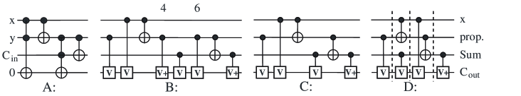
A likely optimal quantum circuit for the 3-input full adder can be constructed from its well-known reversible implementation illustrated in Figure 3A. We first substitute quantum circuits for the Peres gates [20] each of which is a Toffoli-CNOT pair (see Figure 3B). We then apply the templates. In this case, gates 4 and 6 can be moved together and match the gate-inverse rule. So, they are both deleted leading to the circuit in Figure 3C. Finally, we apply the level compactor and the circuit is transformed into the one illustrated in Figure 3D (different logic levels are separated by dashed vertical lines). The number of levels in the compacted circuit is 4, and this is minimum due to having 4 gates with targets on qubit .
5.1 Other templates
It is possible to construct the templates in other gate libraries and then use the discussed cost reduction and level compaction algorithms verbatim. Constructing the templates for the finite (those seem to be more physical) gate libraries may be reduced to finding the rewriting rules by hand and generalizing them into the templates, or running a computer search. A parameterization/classification of the templates in this case may be helpful. However, in the libraries with an infinite number of gates a classification is necessary. We suggest that each template (template class) is written in the circuit form and followed by an algebraic expression conditional upon which the template applies. For example, in the library with single qubit rotations and CNOT gates the following template might be constructed , where . Application of such template can be thought of as finding two single qubit rotations about the same axis (not necessarily the conventional , or , but a possible combination of them), that can be commuted until they are neighbors, and then they get replaced by a single cumulative rotation. Another example of a template for this gate library could be , which could be used to replace some three gates with one, or, for instance, eliminate all gates from a given circuit. In the gate library with controlled gates, the following template is possible , conditional upon gate being a self inverse. This template is a generalization of the one used in this paper (third template in Figure 1), but it captures an infinite number of the rewriting rules. Other templates are possible and depend on the gate base considered. The discussed examples are not intended to be treated as complete review of the possible templates, rather an illustration what kind of templates may be constructed.
6 Numerical results
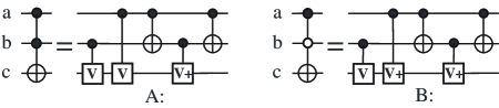
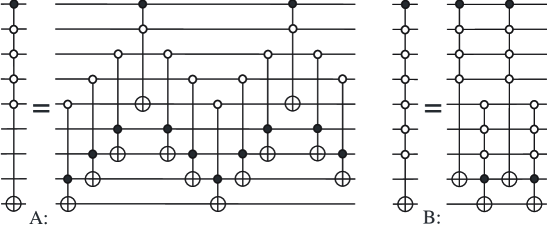
Reversible logic and quantum arithmetic circuits are often specified with NOT, CNOT and Toffoli gates [2, 5, 15, 17, 19], rather than with gates from the NCV set. Circuits with multiple control Toffoli gates have been studied extensively and synthesis procedures exist. To process these circuits we need to transform every Toffoli gate into a circuit with NOT, CNOT, controlled- and controlled- gates. We use the circuit in Figure 4A for this purpose. Due to the symmetry properties of the NCV and Toffoli gates (interchangeability of the controlled- and controlled- gates in quantum NCV circuits for reversible functions [16], symmetry of Toffoli gate controls, and self-inverse property of the Toffoli gate), there exist 8 distinct but equivalent NCV circuits for a Toffoli gate. In our procedure we use only two of them: the circuit in Figure 4A and its inverse, and keep the one resulting in a better circuit simplification. Empirical test have shown that the use of other six transformations will not yield any new improvements.
6.1 Multiple control Toffoli gate simulations
Multiple control Toffoli gates and their variants with negated controls are a popular basis for the synthesis of reversible circuits and are often used to construct quantum circuits. For instance, multiple control Toffoli gates are used in quantum error correcting circuits right after the syndrome was found to correct errors [19]. Even more importantly, multiple control Toffoli gates are at the heart of amplitude amplification technique [3] that is often considered as a separate class of quantum algorithms, of which there are only a few. Thus, multiple control Toffoli gates are indispensable for quantum computations, and it is very important to have efficient quantum circuits for them. Implementations of multiple control Toffoli gates were studied in [1, 2]. In the following, we simplify and compact levels in the multiple Toffoli gate circuits described in [1, 2] using our templates based algorithms. We compare our results to those presented initially. Table 1 summarizes the results.
The results in Table 1 show that the set of multiple control Toffoli gates of size realizations with gate count of (Lemma 7.2 in [2]) are always simplified to the circuits with gates. Based on the regularity and predictability of this simplification, we conjecture this will always be the case. Further, our experiment showed that asymptotically we get a reduction in the number of gates and in the number of logic levels required in simulation of the multiple control Toffoli gates. Similarly, circuits for multiple control Toffoli gates with gates and depth seem to always simplify to the circuits with gates and having depth .
Multiple control Toffoli gates can be implemented with a single auxiliary qubit as discussed in Corollary 7.4 [2]. Using our tool we achieved upper bound (for ) for the number of gates and the number of levels required in multiple control Toffoli gate simulations with a single auxiliary qubit using just the decomposition from Lemma 7.2 of [2]. We stress that the above formulas are upper bounds since we did not yet apply our techniques to simplify such circuits. There must be a clever approach in which both types of auxiliary qubit decompositions are used in the construction due to Corollary 7.4 [2], and depending on whether the final gate count or depth needs to be optimized, the choice for a particular multiple Toffoli gate substitution may vary.
Multiple control Toffoli gates with negations may also be useful in some applications. A canonical implementation of such gates ([19] Figures 4.11 and 4.12) assumes a logic layer of NOT gates preparing the literals in the right polarity followed by a multiple control Toffoli gate with all positive controls and a level of NOT gates returning the values of literals to the positive polarity. This makes multiple control Toffoli gates with negative controls marginally more expensive than the multiple control Toffoli gates with only positive controls. In the following, we show that a multiple control Toffoli gate with some but not all negative controls can be implemented with the same cost as a multiple control Toffoli gate of the same size with only positive controls.
Given that the 3-qubit Toffoli gate with a single negated control can be implemented with the same (minimal) number of gates as a 3-qubit Toffoli gate with positive controls [16] (see Figure 4B), such gate can be used in the circuit proposed by Barenco et al. [2] to implement multiple control Toffoli gates with some but not all negations with no cost overhead. Such simulation is illustrated in Figure 5A.
Furthermore, such multiple control Toffoli gate with some but not all negative controls implementations ([2], Lemma 7.2) rely on a similar strategy to simplify and compact levels as the one used for multiple control Toffoli gate with all positive controls. Therefore, each multiple control Toffoli gate with some but not all negative controls can be implemented with auxiliary qubits, CNOT, controlled- and controlled- gates, and logic levels . Using the simulation illustrated in Figure 5B one can construct multiple control Toffoli gate with some but not all negations and requiring a single auxiliary qubit with no more than gates and the same number of logic levels (for ).
Implementation of multiple control Toffoli gate with all negations requiring auxiliary qubits will require 2 extra NOT gates, however, the number of levels will not increase. Similarly, a multiple control Toffoli gate with all negations simulation with a single auxiliary qubit will require 4 extra NOT gates with no increase in the number of logic levels (upper bound).
A similar argument holds in the case of the decomposition form [1], but we do not discuss this here. Rather, we move on to considering other types of circuits.
6.2 Benchmark circuits
Here we present the results of the application of the templates to a number of quantum circuits implementing various reversible Boolean and quantum arithmetic functions that can be found in the literature. Many reversible/quantum circuits have constant input values and garbage outputs. This typically occurs when a non-reversible function is mapped to a reversible one prior to synthesis as a reversible circuit. In such cases, extra simplifications at the extremities of the circuit can be performed:
-
•
If a gate whose control is an input constant can be moved to the beginning of the circuit then depending on the constant input controlling the gate being 0 or 1 the gate can be either deleted or uncontrolled (assuming an uncontrolled gate has a lesser cost).
-
•
If a gate with the target on a garbage output can be moved to the end, we can delete it as we are not interested with the value of the garbage output.
We took the circuits from [15] composed with NOT, CNOT, and Toffoli gates and compared their quantum realization costs (defined as NCV gate count) before and after applying the templates. We also compacted levels in the simplified circuits and report the number of levels we get. Since [15] do not compact levels in their circuits, we have no comparisons for the number of levels. Table 2 summaries the results.
| Name | Size | NCV GC | Optimized NCV GC | Levels |
|---|---|---|---|---|
| 7 | 40 | 29 | 25 | |
| 4 | 12 | 6 | 4 | |
| 3 | 14 | 10 | 10 | |
| 4 | 32 | 27 | 21 | |
| 10 | 72 | 53 | 27 | |
| 12 | 108 | 82 | 50 | |
| 5 | 24 | 14 | 9 | |
| 5 | 25 | 11 | 8 | |
| 5 | 13 | 9 | 5 | |
| 3 | 9 | 7 | 7 | |
| 7 | 49 | 40 | 28 | |
| 4 | 23 | 21 | 16 | |
| 8 | 44 | 31 | 19 | |
| 10 | 76 | 55 | 34 | |
| 15 | 112 | 86 | 41 |
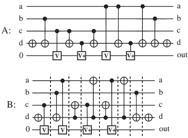
Let us describe the simplification procedure for one of these benchmark circuits: the 5-qubit oracle function . It leaves the first four inputs unchanged and inverts the last one if, and only if, the first four represent an integer divisible by 5. We first found a Toffoli gate realization (circuit in Table 2). We then applied the template based optimization techniques described above. The resulting circuit is illustrated in Figure 6A. If the inputs are not required to be passed through unchanged, the last three gates may be dropped. We next applied the level compaction algorithm. The compacted version of the circuit in Figure 6A is illustrated in Figure 6B. Note how the level compactor changes the form of the circuit to allow fewer levels. This happens when even size templates are applied to change the form of the circuit to facilitate further level compaction. Unless this is done, circuit in Figure 6A cannot be compacted to have less than 10 logic levels. This is because qubit is used 10 times as a control/target. If the inputs need not be recovered, the depth of such computation is only 5 logic levels, and the number of gates required is 9.
Finally, we applied the simplification procedure to some levelled quantum circuits for adder, comparator and modular exponentiation type function (the latter is an important part of the Shor’s factoring algorithm) reported in [5, 17]. We took their circuits, substituted quantum implementations of the Toffoli gates where needed, simplified them and compacted levels (treating each circuit as non-levelled). In the circuit with Fredkin gates ([17], Fig. 4) we used CNOT-Toffoli-CNOT decomposition of the Fredkin gate, and in the circuit with single negative control Toffoli gates ([17], Fig. 5), we used circuit from Figure 4B. The results are reported for 3 circuits that can be found in [5] and 3 circuits from [17] (Table 3).
| Name | Size | NCV GC | Levels | Optimized | Optimized | Runtime |
|---|---|---|---|---|---|---|
| NCV GC | levels | |||||
| [5], Fig. 5 | 35 | 368 | 86 | 303 | 53 | 1.883 sec |
| [5], Fig. 6 | 24 | 172 | 49 | 110 | 27 | 0.341 sec |
| [5], Fig. 7 | 26 | 337 | 101 | 287 | 61 | 1.903 sec |
| [17], Fig. 2 | 10 | 60 | 47 | 34 | 20 | 0.07 sec |
| [17], Fig. 4 | 15 | 70 | 44 | 58 | 23 | 0.210 sec |
| [17], Fig. 5 | 30 | 168 | 37 | 112 | 21 | 0.301 sec |
7 Future work
There are several possibilities to improve our simplification approach. We are interested to develop a smart automated procedure for substituting quantum circuits for multiple control Toffoli gates. The search for the new templates can be accomplished finding all identities of the given size and applying templates to simplify them. All identities that do not simplify are the new templates. Such search method is also suitable for proving the completeness of the set of the templates found.
As far as level compaction goes, we presented a very simple and greedy algorithm. We expect that our results for the number of levels can be improved through use of a smarter level compaction algorithm. However, we believe that the templates could still serve as an efficient core for such improved level compactor.
Finally, we are interested in extending the experimental results of the templates application to other sets of quantum gates including rotation gates and elementary pulses (NMR quantum technology; this will be a technology-specific optimization), and to account for different architectures (which should be straightforward since each undesirable gate can be punished with a high cost). Since the templates definition is based on the properties of matrix multiplication only, they can be applied in any quantum gate library, and for any cost metric.
8 Conclusion
We have introduced quantum templates and demonstrated how they can be applied for quantum circuit simplification and level compaction. Templates can be developed for any type quantum circuit, and can be applied for various cost metrics (simple gate count, weighted gate count, non-linear metrics). We implemented our algorithms in C++ and demonstrated the effectiveness of our approach using a variety of previously published circuits. In our tests, we first target gate minimization and then compact the logic levels in the simplified circuit. In particular, we reduced the sizes and number of logic levels in the best known multiple control Toffoli gate quantum realizations (including multiple control Toffoli gates with negative controls) and in a number of arithmetic quantum circuits presented by previous authors.
Appendix
Consistency of the template definition is based on the following four lemmas.
Lemma 1: For any circuit realizing a quantum function , circuit is a realization for .
Proof: This statement follows from the properties of matrix multiplication operation.
Lemma 2: For any rewriting rule its gates satisfy the following: , where denotes the identity matrix (transformation).
Proof: The following set of equalities constructed using the rule for a single gate proves the statement.
Lemma 3: For an identity and any parameter is a rewriting rule.
Proof: Proof of this statement follows from the previous one by renaming the subscripts and listing the equalities in the reverse order.
Lemma 4: If , then .
Proof: The following proves the statement.
Acknowledgements
This work was supported by PDF and Discovery grants from the National Sciences and Engineering Research Council of Canada.
References
- [1] M. Asano and C. Ishii, New structural quantum circuit simulating a Toffoli gate, quant-ph/0512016, 2005.
- [2] A. Barenco, C. H. Bennett, R. Cleve, D. P. DiVinchenzo, N. Margolus, P. Shor, T. Sleator, J. A. Smolin, and H. Weinfurter, Elementary gates for quantum computation, Physical Review A, 52:3457--3467, quant-ph/9503016, 1995.
- [3] G. Brassard, P. Hyer, M. Mosca, and A. Tapp, Quantum Amplitude Amplification and Estimation, quant-ph/0005055, 2000.
- [4] D. G. Cory, R. Laflamme, E. Knill, L. Viola, T. F. Havel, N. Boulant, G. Boutis, E. Fortunato, S. Lloyd, R. Martinez, C. Negrevergne, M. Pravia, Y. Sharf, G. Teklemariam, Y. S. Weinstein, and W. H. Zurek, NMR Based Quantum Information Processing: Achievements and Prospects, quant-ph/0004104, 2000.
- [5] T. G. Draper, S. A. Kutin, E. M. Rains, and K. M. Svore, A logarithmic-depth quantum carry-lookahead adder, quant-ph/0406142, 2004.
- [6] M. R. Geller, E. J. Pritchett, A. T. Sornborger, F. K. Wilhelm, Quantum computing with superconductors I: Architectures, quant-ph/0603224, 2006.
- [7] H. Häffner, W. Hänsel, C. F. Roos, J. Benhelm, D. Chek-al-kar, M. Chwalla, T. Körber, U. D. Rapol, M. Riebe, P. O. Schmidt, C. Becher, O. Gühne, W. Dür, and R. Blatt, Scalable multiparticle entanglement of trapped ions, Nature 438:643--646, 2005.
- [8] R. Hughes and others, Quantum Computing Roadmap, University of California for the National Nuclear Security Administration, of the US Department of Energy, http://qist.lanl.gov, 2004.
- [9] W. N. N. Hung, X. Song, G. Yang, J. Yang, and M. A. Perkowski, Quantum logic synthesis by symbolic reachability analysis, Design Automation Conference, pages 838--841, 2004.
- [10] K. Iwama, Y. Kambayashi, and S. Yamashita, Transformation rules for designing CNOT-based quantum circuits, Design Automation Conference, pages 419--424, New Orleans, Louisiana, USA, 2002.
- [11] J. A. Jones and E. Knill. Efficient refocussing of one spin and two spin interactions for NMR, J. Magnetic Resonance, 141:322- 325, quant-ph/9905008, 1999.
- [12] J. A. Jones, R. H. Hansen, and M. Mosca, Quantum logic gates and nuclear magnetic resonance pulse sequences, J. Magnetic Resonance, 135:353--360, quant-ph/9805070, 1998.
- [13] C. Lomont, Quantum circuit identities, quant-ph/0307111, 2003.
- [14] D. Maslov, G. W. Dueck, and D. M. Miller, Toffoli network synthesis with templates, IEEE Transactions on CAD, 24(6):807--817, 2005.
- [15] D. Maslov, G. W. Dueck, and N. Scott, Reversible logic synthesis benchmarks page, http://www.cs.uvic.ca/~dmaslov/, 2006.
- [16] D. Maslov and D. M. Miller, Comparison of the cost metrics for reversible and quantum logic synthesis, IET Computers & Digital Techniques, 1(2):98-104, quant-ph/0511008, 2007.
- [17] R. V. Meter and K. M. Itoh, Fast quantum modular exponentiation, Physical Review A, 71(052320), quant-ph/0408006, 2005.
- [18] M. Möttönen and J. J. Vartiainen, Decompositions of general quantum gates, quant-ph/0504100, 2005.
- [19] M. Nielsen and I. Chuang, Quantum Computation and Quantum Information, Cambridge University Press, 2000.
- [20] A. Peres, Reversible logic and quantum computers, Physical Review A, 32:3266--3276, 1985.
- [21] V. V. Shende, S. S. Bullock, and I. L. Markov, Synthesis of quantum logic circuits, IEEE Transactions on CAD 25(6):1000--1010, quant-ph/0406176, 2006.
- [22] V. V. Shende, A. K. Prasad, K. N. Patel, I. L. Markov, and J. P. Hayes, Algorithms and data structures for simplifying reversible circuits, ACM J. of Emerging Technologies in Comp. Sys., 2(4), October 2006.
- [23] J. A. Smolin and D. P. DiVincenzo, Five two-bit quantum gates are sufficient to implement the quantum Fredkin gate, Physical Review A, 53:2855--2856, 1996.
- [24] T. Toffoli, Reversible computing, Tech memo MIT/LCS/TM-151, MIT Laboratory for Computer Science, 1980.
- [25] L. M. K. Vandersypen, M. Steffen, G. Breyta, C. S. Yannoni, M. H. Sherwood, and I. L. Chuang, Experimental realization of Shor’s quantum factoring algorithm using Nuclear Magnetic Resonance, Nature 414:883--887, quant-ph/0112176, 2001.
- [26] J. Zhang, J. Vala, S. Sastry, and K. B. Whaley, Geometric theory of nonlocal two-qubit operations, Physical Review A, 67(042313), quant-ph/0209120, 2003.