Probabilistic Quantum Gates between Remote Atoms
through Interference of Optical Frequency Qubits
Abstract
We propose a scheme to perform probabilistic quantum gates on remote trapped atom qubits through interference of optical frequency qubits. The method does not require localization of the atoms to the Lamb-Dicke limit, and is not sensitive to interferometer phase instabilities. Such probabilistic gates can be used for scalable quantum computation.
Entangled quantum states, at the heart of quantum information processing, are notoriously difficult to generate and control. Generating entangled states becomes dramatically simpler when the entanglement operations are allowed to succeed with only a finite (perhaps small) probability, as long as it is known when the operations succeed 1 ; 2 ; 3 ; 4 ; 4b . If entangling gates can be implemented in such a probabilistic fashion, it has recently been shown that scalable quantum computation is still possible, no matter how small the gate success probability 5 ; 6 . Compared with deterministic gates, the additional overhead in resources (such as the number of qubit manipulations) for probabilistic quantum computation scales only polynomially with both the size of the computation and the inverse of the gate success probability 5 .
There have been recent proposals for implementation of probabilistic gates 6 ; 7 ; 8 , using atomic qubits inside optical cavities. In this paper, we propose a new scheme for probabilistic quantum gate operations that act on trapped atoms or ions in free space (with or without cavities). Compared with previous methods, this scheme has two outstanding features. First, optical frequency qubits are used to connect and entangle matter qubits at distant locations. The two states comprising this optical qubit have the same polarization, but differ in frequency by atomic qubit splitting (typically in the microwave region for hyperfine atomic qubits). These closely-spaced frequency components have basically zero dispersion in typical optical paths, thus this optical qubit is highly insensitive to phase jitter inherent in optical interferometers. Such optical frequency qubits have been demonstrated in a very recent experiment exp , through control of a trapped cadmium ion with ultrafast laser pulses. Second, the proposed entangling scheme does not require localization of the atoms to the Lamb-Dicke limit. Motion of the atomic qubits can be larger than the optical wavelength. Although ions can be localized well under the Lamb-Dicke limit through laser cooling in a strong trap, the elimination of this stringent requirement should greatly simplify experiments. This is particularly important for ions confined in miniature electrode structures fabricated on a chip exp2 ; surfacetrap , where ion heating may become more significant deslauriers . This feature is also crucial for neutral atom qubits, where confinement to the Lamb-Dicke regime is very difficult.
Our scheme is illustrated in Fig. 1. The qubit is represented by two ground state hyperfine levels of an alkali-like atom (ion), with , and . These “clock” states are particularly insensitive to stray magnetic fields. In the figure, for simplicity, we take , which is the case for ions such as 111Cd+, but the scheme works for any value of . To perform a probabilistic gate on two remote atoms 1 and 2, we first excite both of the atoms to the excited electronic state with a -polarized ultrafast laser pulse note1 . We assume the laser has a bandwidth which is larger than the hyperfine splitting ( GHz for 111Cd+), but smaller than the fine structure splitting between and ( THz for 111Cd+). Typical picosecond pulses used in experiments (bandwidth GHz) satisfy these requirements exp . Under the above condition, we can assume the pulse only drives the D1 transition from the ground state to the excited state note2 . Due to dipole selection rules, for a -polarized pulse, only the hyperfine transitions and are allowed, where the upper hyperfine spin . Thanks to the selection rules, each qubit state is transferred to a unique excited hyperfine level after the pulsed laser excitation. This point is critical for successful gate operation.
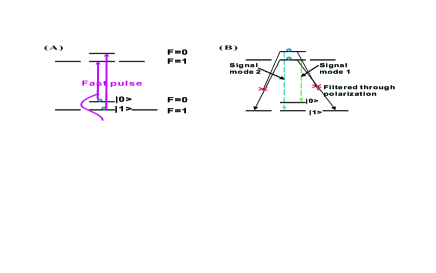
After this laser excitation, the atoms eventually decay back to their ground states. There are several decay channels, through the emission of either -polarized or -polarized spontaneous emission photons (see Fig. 1b). We first consider the decay channels with a -polarized emission photon. In this case, the excited levels and can only decay back to the ground states and , respectively. While photons from these two decay channels have the same polarization, they have slightly different frequencies. The frequency difference is given by , the sum of the hyperfine splittings of the ground and excited states. This frequency difference is typically much larger than the natural linewidth of the excited level note3 , so the corresponding photons from the two -decay channels are well-resolved in frequency. This defines two frequency modes for the emitted photon field, and we call them and modes, respectively. If the atom is initially in the qubit state , then after this excitation-decay process the atom-photon system evolves to an entangled state
| (1) |
if we only collect the photon from the decay channels, where and represent a single photon state in the frequency modes and , respectively. Any photon from the decay channels is assumed to be blocked through a polarization filter. This result is somewhat similar to the previous demonstration of the atom-photon entanglement 4 ; 4b , but there are important differences. First, the final state keeps track of the information of the initial qubit state. Thus, the scheme here is not just an entangling protocol 10 , but is instead an entangling gate with the final quantum state depending on the initial state. As we will see later, this type of gate can form the basis for scalable quantum computation, and is therefore more powerful than merely an entangling operation. Second, the spontaneous emission photon with either frequency or has the same spatial mode, so good spatial mode-matching of this photonic qubit is possible even if we increase the solid angle of collection. In the previous entangling protocol 10 ; 4 ; 4b , the quantum information is carried by different polarization modes of the photon, which have different spatial emission patterns. This requires small collection solid angles in order to both maintain orthogonality and ensure adequate spatial matching of the photonic qubit states.
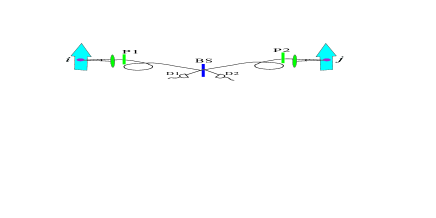
To perform a gate on two remote atoms, the spontaneous emission photons from the decay channels in each atom are collected in a certain solid angle, and directed onto a beam splitter for interference (see Fig. 2). The output of the beam splitter is measured by two single-photon detectors. We keep the resulting outcome atomic state only when we register a photon from each detector. In this case, what we have performed is a “measurement gate” on the atoms 1 and 2. It corresponds to a quantum non-demolition measurement of the operator , where (or ) stands for the (or ) component of the Pauli matrix associated with atomic qubit . After the coincidence measurement of photons on both detectors, the atomic state is projected to the eigenspace of with eigenvalue. To see this, we note that before the measurement, the state of both atom-photon systems can be written as , where has the form of Eq. (1), and can be written as . To register a photon from each detector, the two photons before the beam splitter need to go to different sides, which means they should be in the anti-symmetric component (for photons in the symmetric states, they always go to the same detector). So, given that the photons take separate paths after the beam-splitter, the state of the atoms 1,2 is given by the projection
where is the corresponding projector, and is a trivial additional single-bit gate on atom 1 which we will neglect in the following. This measurement gate, of course, only succeeds with a finite probability. The overall success probability is given by , where is the quantum efficiency of each detector, is the photon collection efficiency (proportional to the solid angle), and is the branching ratio for the atom to decay along the channel. We have an additional factor of in describing the average probability for the two spontaneous emission photons to go to different detectors (averaged over all the possible initial atomic states). In the above contributions to the success probability, the collection efficiency is typically the smallest and thus dominates the overall efficiency. That is why is important to increase the collection solid angle as much as possible. Alternatively, one can also increase this efficiency with the use of optical cavities surrounding the atoms CQED .
The above measurement gate is robust to noise. We do not require that the atoms be localized to the Lamb-Dicke limit. In general, atomic motion occurs with a time scale of the trap frequency , typically much smaller than the decay rate of the excited atomic level. Thus, for each spontaneous emission pulse, we can safely assume the atom to be in a fixed but random position . In this case, both of the frequency components and will acquire the same random phase factor proportional to , where is the wave vector associated with the spontaneous emission photon. This overall phase therefore has no effect on the resultant measurement gate as shown in Eq. (2). If we take into account of the motion of the atom within the pulse duration, the pulse from this moving atom also has a slight Doppler shift in its frequency, where is the random atom velocity at that moment, and is the characteristic length scale for the atom oscillation. We need this random Doppler shift to be significantly smaller than the bandwidth of the pulse in order to have a good shape matching of the spontaneous emission pulses from different atoms. So, there is a further requirement , which is consistent with the assumption . Finally, this gate is also very insensitive to the birefringence and the phase drift in the optical interferometer. Both of the components and have the same polarization, and they are very close in frequency. So, they essentially experience the same noisy phase shift under fluctuation of the optical path length, again cancelling.
We have shown how to perform a probabilistic measurement gate on remote atoms by projecting the system state to the eigenspace of the operator. Such a gate only succeeds with a small probability, but it is very robust to noise. This type of probabilistic gate can lead to efficient quantum computation, no matter how small the success probability is 5 ; 6 ; note4 . The proof is based on efficient construction of the two-dimensional (2D) cluster state, which has been shown to be a sufficient resource for universal quantum computation 11 . To construct a 2D cluster state of size , the number of pulses (elementary operations) scales with by , and scales with the inverse of the gate success probability nearly polynomially. The exact scaling formula can be found in Ref. 5 , where it is derived for the case of probabilistic controlled phase flip (CPF) gates. For the ZZ measurement gate, the scaling formula is almost the same. To see this, we can simply note the following two facts: (1) If one starts with two qubits (atoms) in the co-eigenstate of and (a product state), the final state after a ZZ measurement is projected to a co-eigenstate of the stabilizer operators and , which is equivalent to the two-qubit cluster state under single-bit rotations 6 ; (2) Assume that one has prepared two 1D cluster chains, each of qubits. The stabilizer operators for the boundary qubits n and n+1 of the two chains are denoted by and , respectively. A ZZ measurement of these two boundary qubits generates the new stabilizer operators and . This operation actually connects the two chains into a cluster state of qubits (the central qubits n and n+1 together represent one logic qubit with the encoded and or ). From these two facts, we can derive the recursion relations. Following the same argument as in the case for the CPF gate 5 , we can show that started with two cluster chains each of n qubits, the average length of the cluster state after this probabilistic measurement gate is given by , where the critical length and is the gate success probability. Compared with the case of the CPF gate, the only difference is the critical length changes from to , and such a change is negligible in the case of a small success probability with . So, for this ZZ measurement gate, we find nearly the same scaling formula derived in Ref. 5 .
In summary, we have proposed a scheme for probabilistic gates on remote trapped atoms or ions in free space, based on interference of optical frequency qubits from the atomic spontaneous emission driven by ultrafast laser pulses. This gate scheme does not require localization of the atoms to the Lamb-Dicke limit, and is robust to practical phase noise in the optical interferometers. This type of probabilistic gate could lead to alternative way for efficient quantum computation.
We thank R. Raussendorf, B. Blinov, S. D. Barrett, and P. Kok for helpful discussions. This work was supported by National Science Foundation award 0431476 and the ITR program, the National Security Agency and the Disruptive Technology Organization under Army Research Office contract W911NF-04-1-0234, and the A. P. Sloan Foundation..
References
- (1) L. M. Duan, M. D. Lukin, J. I. Cirac, P,. Zoller, Nature 414, 413 (2001).
- (2) E. Knill, R. Laflamme, and G. Milburn, Nature 409, 46 (2001).
- (3) A. Kuzmich, et al., Nature 423, 731 (2003); C. H. van der Wal et al., Science 301, 196 (2003).
- (4) B. B. Blinov, D. L. Moehring, L.-M. Duan, C. Monroe, Nature 428, 153-157 (2004).
- (5) D. L. Moehring, M. J. Madsen, B. B. Blinov, and C. Monroe, Phys. Rev. Lett. 93, 090410 (2004).
- (6) L.-M. Duan and R. Raussendorf, Phys. Rev. Lett. 95, 080503 (2005).
- (7) S. D. Barrett, P. Kok, Phys. Rev. A 71, 060310(R) (2005).
- (8) L.-M. Duan, B. Wang, J. Kimble, Phys. Rev. A 72, 022320 (2005).
- (9) Y. L. Lim et al., Phys. Rev. A 73, 012304 (2006); Y. L. Lim, A. Beige, L. C. Kwek, Phys. Rev. Lett. 95, 030505 (2005).
- (10) M. J. Madsen et al., quant-ph/0603258 .
- (11) D. Stick et al., Nature Physics 2, 36 (2006); D. Kielpinski, C. Monroe, and D. J. Wineland, Nature 417, 709 (2002).
- (12) S. Seidelin, et al., quant-ph/0601173 (2006).
- (13) L. Deslauriers, et al., quant-ph/0602003 (2006).
- (14) If an ultrafast laser pulse is not available, one can replace it by two phase-locked narrow-band pulses which drives the D1 transitions and (), respectively.
- (15) For 111Cd+ (or for any atoms with the nuclear spin ), one can also drive the D2 line , where the two corresponding hyperfine transitions are given by and with , see Ref. exp .
- (16) For instance, for 133Cs atoms or 111Cd+ ions, the hyperfine splitting is about GHz ( GHz), while the natural linewidth of the excited level (the inverse of the lifetime) is around MHz ( MHz). In both cases, the condition is well satisfied.
- (17) L.-M. Duan, B. B. Blinov, D. L. Moehring, C. Monroe, Quant. Inf. Comp. 4, 165-173 (2004).
- (18) J. McKeever, J. R. Buck, A. D. Boozer, and H. J. Kimble, Phys. Rev. Lett. 92, 143601 (2004); P. Maunz, et al., Nature 428, 50 (2004); J. A. Sauer, et al., Phys. Rev. A69, 051804 (2004); G. Guthorlein, et al.,Nature 414, 49 (2001); A. Mundt, et al., Phys. Rev. Lett. 89, 103001 (2002).
- (19) Note, however, that the noise model assumed in Ref. 6 is more restrictive. It assumes there that if a gate fails, states of the two target qubits are not destroyed, but instead, they are subject only to Z type of errors (without bit flips from to , for instance). In our physical implementation, however, due to the existence of -decaly channels (which are alwyas there for any realistic atoms), there is a significant probability of bit-flip errors when a gate fails. So, in the case of a gate failure, one needs to trace out the destroyed qubits. The noise model here is exactly the same as what is assumed in Ref. 5 . We can follow the contruction there to prove scalalbility under this kind of noise model.
- (20) H.J. Briegel and R. Raussendorf, Phys. Rev. Lett. 86, 910 (2001); R. Raussendorf and H. J. Briegel, Phys. Rev. Lett. 86, 5188 (2001).