Present address: ]Sektion Physik der Ludwig-Maximilians-Universität, Schellingstrasse 4, D-80799 München, Germany. Present address: ]Laboratoire d’Optique Appliquée, Centre de l’Yvette, F-91761 Palaiseau Cedex, France.
Diffraction of a Bose-Einstein Condensate in the Time Domain
Abstract
We have observed the diffraction of a Bose-Einstein condensate of rubidium atoms on a vibrating mirror potential. The matter wave packet bounces back at normal incidence on a blue-detuned evanescent light field after a mm free fall. The mirror vibrates at a frequency of kHz with an amplitude of nm. The atomic carrier and sidebands are directly imaged during their ballistic expansion. The locations and the relative weights of the diffracted atomic wave packets are in very good agreement with the theoretical prediction of Carsten Henkel et al. Henkel et al. (1994).
pacs:
03.75.Be, 03.75.Dg, 42.50.VkThe manipulation of ultracold atomic matter waves with optical or magnetic fields close to surfaces is extensively explored in the context of fabricating integrated atom optics devices. The use of the Zeeman interaction due to the magnetic field of microfabricated current carrying wires is currently the most attractive approach Reichel et al. (2001); Folman et al. (2002). The main advantages of this method are the modularity and steadiness of the microchip fabrication. Nevertheless, some drawbacks of this technique exist since one experiences losses of atoms in magnetic traps at close distances to conducting surfaces Jones et al. (2004); Lin et al. (2004); Henkel and Wilkens (1999) due to Johnson noise induced spin flips. This loss mechanism is absent in the vicinity of dielectric surfaces, which can be used as substrates for dipole traps based on optical near fields. In 1991 Ovchinnikov et al. Ovchinnikov et al. (1991) made the seminal proposal of using the difference in the decay lengths of the evanescent fields created by total internal reflections of blue- and red-detuned light beams on a planar dielectric surface to create a trapping dipole potential above the surface. The group of R. Grimm demonstrated this trapping in 2002 Hammes et al. (2003). The proposals of Barnett et al. Barnett et al. (2000) and Burke et al. Burke et al. (2002) enlarge the optical near field trapping geometry to a richer variety of patterns: the basic idea is to take benefit of light injected inside integrated optical structures to design evanescent field traps and guides. Having a similar compactness and versatility as the optical waveguides supporting the evanescent waves, these dipole traps and guides offer an interesting alternative to the current carrying wires on a chip technique.
In this letter we address the action of the evanescent outer part of a light mode propagating in a planar optical waveguide. The experiment performed is similar to the one realized with cold atoms by the group of Jean Dalibard in 1995 Steane et al. (1995). The difference mostly consists in the initial longitudinal coherence of our atomic source. In our experiment, an atomic Bose-Einstein condensate is reflected after a free fall by the evanescent part of a blue-detuned guided optical mode, and is observed in its ballistic expansion after the bounce. The evanescent mirror is made to vibrate, which modulates the phase of the reflected wave function and diffracts the atoms in several sidebands. Atoms bouncing on this potential are also dramatically scattered, which is due to the corrugated structure of the planar waveguide on a nanometer scale. A particular study of the elastic scattering of the atomic wave by the static rough mirror potential is presented elsewhere Perrin et al. (2005). As discussed below, the diffraction in the time domain and the elastic scattering are independent phenomena and we focus here on the study of the first effect. This diffraction of an atomic BEC by a modulated mirror has also similarities with experiments on atomic diffraction performed by a pulsed optical standing-wave Ovchinnikov et al. (1999); Keller et al. (1999). The experimental set-up is described in Colombe et al. (2003). It is based on a double MOT system. From the UHV MOT 87Rb atoms are transferred into a QUIC (Quadrupole and Ioffe Configuration) Esslinger et al. (1998) magnetic trap. An almost pure condensate of atoms is obtained by radio-frequency evaporative cooling inside the QUIC trap. Below the trapped atoms stands an optical waveguide made of a nm thick layer of TiO2 () on the top of a nm SiO2 layer (). This low index gap layer is on the top surface of a high index prism made of a Schott LaSFN15 glass (). The TE2 mode of the waveguide is excited through evanescent coupling of a mW diode laser beam detuned by GHz on the blue side of the transition. The field decay length of the TE2 guided mode in the vacuum is nm. The number of spontaneous photon per atom during the bounce is about in the situation where the atoms penetrate in the evanescent field with a falling height of mm. The vibration of the evanescent mirror is obtained by a sinusoidal modulation of the diode current. The resulting modulation depth of the a.c. Stark shift potential is , where and . The power modulation depth is measured directly with a photodiode. The detuning modulation depth is measured by calibrating the frequency shift versus the diode current using the atomic frequency reference in a saturated absorption experiment. The modulation depth is times less than : the modulation of the reflecting potential is thus essentially due to the modulation of the detuning.
| Experiment | (a) | (b) | (c) |
|---|---|---|---|
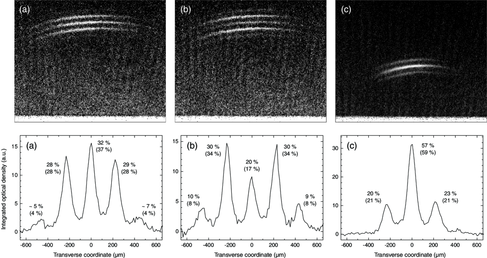
Three kinds of BEC diffraction experiments have been performed. They differ by the falling heights of the atomic cloud and by the modulation depths of mirror potential. The parameters are summarized in table 1. In the (a) and (b) experiments the atomic condensate is released from the QUIC trap centered mm above the dielectric surface. In the (c) experiment the condensate is first magnetically transported to a height of mm above the surface before being released from the trap Colombe et al. (2004). The corresponding free fall times down to the dielectric surface are ms in cases (a,b) and ms in case (c). In addition to the incident vertical velocity, a small horizontal velocity (mm/s for all experiments) results in a slight tilt of the clouds after reflection. The modulation depths are in (a), in (b), and in (c). These modulation depths correspond to vibrating amplitudes of the mirror of nm, nm, and nm, respectively. The frequency of the modulation is kept the same, kHz, throughout these experiments. The diffracted wavepackets are detected by absorption imaging with a horizontal laser beam (Fig. 1, upper part). In order to accurately measure the atomic populations in the different elastically scattered diffraction orders, the optical density is integrated along circles of growing radii. The relative weights are measured on the resulting profile (Fig. 1, lower part) Cir .
| Diffraction orders | |||||
| Expected: (a) and (b) | |||||
| Measured: (a) | |||||
| Measured: (b) | |||||
| Expected: (c) | |||||
| Measured: (c) |
The diffracted populations are clearly resolved with a time of flight ms (a,b) or ms (c) after the reflection on the evanescent mirror. The measured distances between the diffracted orders are reported in table 2. A remarkable feature of this experiment lies in the direct visualization of the sidebands. The wavenumber separations are transferred into wave packet separations that allow a direct and accurate measurement of the energy intervals and relative weights of the sidebands. The scattering of the matter wave by the mirror roughness and the diffraction of the same matter wave by the mirror vibration are different in nature and their effects are indeed clearly separated on the absorption images. The first effect is an elastic momentum exchange which spreads the reflected atoms over an elastic scattering sphere. The second is a transfer of energy, giving birth to sidebands. Given our particular condition of initial kinetic energy for say, mm free fall, the velocity difference along between the carrier and the first sidebands is ( is the photon recoil velocity) with a modulation frequency of kHz. The momentum scattering due to diffuse reflection affects essentially the horizontal velocity ( along Perrin et al. (2005)). Hence it does not prevent the observation of resolved sidebands along the vertical direction. This leads us to interpret our diffraction experiments with a one-coordinate model, namely an incident plane wave at normal incidence with a perfect mirror.
Let us first consider the reflection of the plane atomic wave function on a vibrating infinite repulsive potential Wav . We assume that the velocity of the mirror coordinate is always much less than the atomic group and phase velocities, so that the incident wave function can be written as . The incident and reflected waves fulfill the boundary condition at any time. In the case of a harmonically vibrating mirror , the reflected wave function may be expanded as a sum of a carrier and diffracted sidebands , where the sideband amplitudes are Bessel functions of the first kind and the atomic phase modulation amplitude is . The energy separation between sidebands is and the corresponding wavenumbers are ( is the mass of the atom) as long as the energy transfer is much less than the incident kinetic energy.
In our situation the reflecting potential is an exponential whose amplitude is harmonically modulated . As the potential is exponential, the amplitude modulation is equivalent to an overall translation; in the case of a weak modulation depth , this translation is also harmonic: with . The main difference between the infinitely steep and the evanescent potentials lies in the continuous variation of the incident matter wave momentum inside the potential in the last case. Henkel et al. have calculated the atomic phase modulation imprinted by the vibrating mirror in a semiclassical model Henkel et al. (1994). It is assumed that the incident atomic de Broglie wavelength is much smaller than nm, and that the classical atomic trajectory is not much affected by the vibration of the potential. In our experiment the atomic BEC cloud is released mm or mm above the dielectric substrate. When the atoms hit the evanescent mirror, the de Broglie wavelength is respectively nm or nm. These values are indeed much smaller than . Furthermore, our modulation depth is at maximum and ensures that the vibration barely perturbs the classical atom trajectory. Under these conditions the semi-classical approach proposed by Henkel et al. is valid.
The predicted diffraction weights are
| (1) |
where and . is the ratio of the wavenumber interval between successive sidebands and the exponential decay factor of the evanescent wave. The reduction factor falls exponentially for , so that the maximum momentum transfer is in the order of as expected from the Heisenberg uncertainty relation. The values in parentheses in Fig. 1 are the weights calculated by the formula (1) where the experimental values serve as inputs. The agreement between the calculated and the observed weights is within accuracy in the worst case.
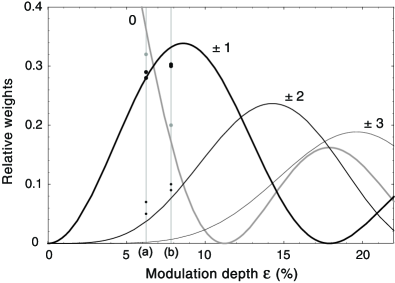
The figure 2 illustrates the expected relative weights of the diffracted orders as a function of the modulation depth for atoms falling a height of mm and a mirror modulation frequency of kHz. It clearly shows that small modulation depths are the better choice to combine high diffraction efficiency on a few sidebands.
In summary, this experiment demonstrates the diffraction of an atomic matter wave by a vibrating rough mirror potential. Despite the elastic diffusion of the atoms, the signal of diffraction is still clear-cut because of the monochromaticity of the atomic source. However, it would be misleading to associate the quantum nature of the atomic diffraction to the Bose-Einstein phase coherence. The dynamics of the bouncing is not even determined by the density term of the Gross-Pitaevskii equation as it is in the Hannover experiment Bongs et al. (1999): the expanding BEC evolves like a free non interacting particle gas already ms after being released from the magnetic trap. The linear Schrödinger equation gives correctly the dynamics of individual atoms, independently of a relative phase between their wave functions. Such a vibrating mirror can be used as a phase modulator in conventional atom optics: it has been implemented in a longitudinal interferometer with three consecutive bounces Szriftgiser et al. (1996), the temporal equivalent of three grating interferometers Keith et al. (1991); Rasel et al. (1995). In these devices, the atomic sources are considered as white light sources and great care is taken to have identical path lengths. Crossing the bridge to non-symmetric path interferometry becomes realistic when the atomic wave comes out of a BEC. Under our experimental conditions, a 2 path interferometer seems realistic under the following conditions: a first separation of order and followed by and bounces respectively, the final recombination being ensured by a last modulation, would lead to a very asymmetric interferometer. With our experimental parameters, appears to be possible. It will require, however, the use of a super-polished substrate as a mirror and possibly a lateral confinement of the atomic wave: up to bounces have been observed with a conventional MOT atomic source at a mm drop height above a curved mirror Aminoff et al. (1993), and a guiding of the matter wave without perturbing the motion perpendicular to the mirror surface can be obtained with magnetic confinement Dekker et al. (2000).
Acknowledgements.
We thank B. M. Garraway for a careful reading of the manuscript. We acknowledge support from the FNS through the ACI-photonique program, the UE through the RTN FASTNet program under contract No. HPRN-CT-2002-00304 and the Conseil Régional d’Ile de France.References
- Henkel et al. (1994) C. Henkel, A. M. Steane, R. Kaiser, and J. Dalibard, J. Phys. II France 4, 1877 (1994).
- Reichel et al. (2001) J. Reichel et al., Appl. Phys. B 72, 81 (2001).
- Folman et al. (2002) R. Folman et al., Adv. At. Mol. Opt. Phys. 48, 263 (2002).
- Jones et al. (2004) M. P. A. Jones et al., J. Phys. B: At. Mol. Opt. Phys. 37, L15 (2004).
- Lin et al. (2004) Y.-J. Lin et al., Phys. Rev. Lett. 92, 050404 (2004).
- Henkel and Wilkens (1999) C. Henkel and M. Wilkens, Europhys. Lett. 47, 414 (1999).
- Ovchinnikov et al. (1991) Y. B. Ovchinnikov, S. V. Shul’ga, and V. I. Balykin, J. Phys. B: At. Mol. Opt. Phys. 24, 3173 (1991).
- Hammes et al. (2003) M. Hammes, D. Rychtarik, B. Engeser, H.-C. Nägerl, and R. Grimm, Phys. Rev. Lett 90, 173001 (2003).
- Barnett et al. (2000) A. H. Barnett et al., Phys. Rev. A 61, 023608 (2000).
- Burke et al. (2002) J. P. Burke et al., Phys. Rev. A 65, 043411 (2002).
- Steane et al. (1995) A. Steane, P. Szriftgiser, P. Desbiolles, and J. Dalibard, Phys. Rev. Lett. 74, 4972 (1995).
- Perrin et al. (2005) H. Perrin, Y. Colombe, B. Mercier, V. Lorent, and C. Henkel, J. Phys.: Conf. Ser. 19, 151 (2005).
- Ovchinnikov et al. (1999) Y. B. Ovchinnikov et al., Phys. Rev. Lett. 83, 284 (1999).
- Keller et al. (1999) C. Keller et al., Appl. Phys. B 69, 303 (1999).
- Colombe et al. (2003) Y. Colombe, D. Kadio, M. Olshanii, B. Mercier, V. Lorent, and H. Perrin, J. Opt. B: Quantum Semiclass. Opt. 5, S155 (2003).
- Esslinger et al. (1998) T. Esslinger, I. Bloch, and T. W. Hänsch, Phys. Rev. A 58, R2664 (1998).
- Colombe et al. (2004) Y. Colombe, H. Perrin, B. Mercier, and V. Lorent, in COLOQ 8, huitième colloque sur les lasers et l’optique quantique, edited by A. Aspect, J. Vigué, and B. Girard (J. Phys. IV France, 2004), vol. 119, pp. 159–160.
- (18) For each experiment, the center of the integration circles corresponds to the point of contact of the atoms with the evanescent wave, translated vertically by the distance covered by the free fall referential that is at rest at the instant of the reflection. The wave packets are adequately fitted with Gaussian functions, which allow a measure of their relative weights and positions.
- (19) The spatial width of the incident wave packet is still large enough to ensure the validity of the plane wave model.
- Bongs et al. (1999) K. Bongs, S. Burger, G. Birkl, K. Sengstock, W. Ertmer, K. Rza̧żewski, A. Sanpera, and M. Lewenstein, Phys. Rev. Lett. 83, 3577 (1999).
- Szriftgiser et al. (1996) P. Szriftgiser, D. Guéry-Odelin, M. Arndt, and J. Dalibard, Phys. Rev. Lett. 77, 4 (1996).
- Keith et al. (1991) D. W. Keith, C. R. Ekstrom, Q. A. Turchette, and D. E. Pritchard, Phys. Rev. Lett. 66, 2693 (1991).
- Rasel et al. (1995) E. M. Rasel, M. K. Oberthaler, H. Batelaan, J. Schmiedmayer, and A. Zeilinger, Phys. Rev. Lett. 75, 2633 (1995).
- Aminoff et al. (1993) C. G. Aminoff, A. M. Steane, P. Bouyer, P. Desbiolles, J. Dalibard, and C. Cohen-Tannoudji, Phys. Rev. Lett. 71, 3083 (1993).
- Dekker et al. (2000) N. H. Dekker et al., Phys. Rev. Lett. 84, 1124 (2000).