Experimental Realization of an NMR Quantum Switch
Abstract
In this paper, we report an experimental realization of quantum switch using nuclear spins and magnetic resonant pulses. The nuclear spins of 1H and 13C in carbon-13 labelled chloroform are used to carry the information, then nuclear magnetic resonance pulses are applied to perform either bypass or cross function to achieve the switching. Compared with a traditional space or time domain switch, this switching architecture is much more scalable, therefore a high throughput switching device can be built simply by increasing the number of I/O ports. In addition, it can be used not only as a device to switch classical information, but also a building block of quantum information networks.
keywords:
Quantum Switch, Nuclear Magnetic Resonance, Quantum Computation, Quantum Information Networks.1 Introduction
The study of quantum information science has expanded rapidly due to the discovery of several efficient quantum algorithms [1][2][3] and the progress in physical implementation schemes. Recent advances in quantum mechanical technology like ion traps [4], optical cavities [5], nuclear magnetic resonance [6], quantum dots [7], and silicon-based solutions [8], have brought scientists a number of ways to realize quantum mechanical applications. In these solutions, Nuclear Magnetic Resonance (NMR) is a mature technology which has wide spread applications in chemistry and medical areas. There have been many reports that demonstrate NMR is capable of implementing a quantum computation system and solving intractable problems [9][10][11][12]. In this paper, we report an experimental realization of 22 NMR quantum switch using 1H and 13C in carbon-13 labelled chloroform (13CHCl3) as the information carrying units.
Digital switching, in general, can be categorized into two major classes - circuit switching and packet switching. For circuit switching, the switching module moves the data in each time slot between the input and output ports. As for packet switching, a packet with either a fixed or variable length is forwarded to the destination according to its header. There are many underlying architectures that can be used to provide the function of switching. For example, time domain switching and space domain switching are two commonly used architectures. In our previous work [13], we have presented a new switching architecture such that digital data can be switched in the quantum domain. The proposed mechanism supports unicasting as well as multicasting, and is scalable and non-blocking. It can be used to build classical and quantum information networks.
Note that, as long as the state of the information carrier can be manipulated according to quantum mechanics, the proposed switching architecture is independent of the underlying technology. In this paper we demonstrate a 22 quantum switch using nuclear spins and NMR pulses. More specifically, the nuclear spins of 1H and 13C in carbon-13 labelled chloroform are used to carry the information to be processed, then RF pulses are applied to perform either bypass or cross action to achieve the function of switching. Compared with a traditional space or time domain switch, this switching architecture is much more scalable. For an nn quantum switch, the space consumption is linear and the time complexity is constant. With these advantages, a high throughput switching device can be built simply by increasing the number of I/O ports.
2 Circuit Implementation of a Quantum Switch
2.1 Quantum Circuits
For the quantum state of a nuclear spin, there are two eigen states, denoted by for spin-up and for spin-down. The state of each spin can be written as a linear combination of these two eigen states, so we have the state of a qubit as
| (1) |
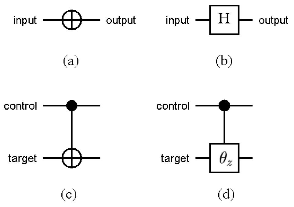
with , and . The state described above exhibits an unique phenomenon in quantum mechanics called superposition. When a particle is in such a superposed state, it has a part corresponding to and a part corresponding to , at the same time. To distinguish the above system from the classical binary logic, a unit that carrying binary information in such a quantum system is referred to as a quantum binary digit, or qubit. A quantum system can be manipulated in many different ways. These operations are generally called quantum gates. A quantum gate must be unitary in its matrix form and can be pictorially described as a rotation on a sphere. For example, a quantum Not (N) gate applied to a single qubit is actually a rotation of around the axis. The symbol of an N gate is shown in Fig.1(a). Note that the horizontal line connecting the input and the output is not a physical wire, instead it represents a qubit under time evolution. Another important gate is the Hadamard (H) gate, as shown in Fig.1(b). The H gate performs a rotation of around the axis of () and is actually an exchange of axis with axis.
Two or more qubits can also form a quantum system jointly. A two-qubit system is spanned by , , , and , i.e.
| (2) |
with , , , and . In general, the space of a multi-qubit system is spanned by the basis of the tensor product of each spaces. An example of two-qubit gate is the Control-Not (CN) gate, as shown in Fig.1(c). A CN gate consists of one control bit and one target bit . The target qubit will be inverted only when the control qubit is . Assuming is the control bit, the gate can be written as CN(), where denotes exclusive-or. A generalization of the CN gate is the Control-phase-shift gate, which shifts the phase of the target qubit for only when the control qubit is . A control-phase-shift gate is shown in Fig.1(d).
Although we can define and implement a multi-qubit gate in a multi-qubit system, it has been shown that two-qubit gates are sufficient to implement any unitary operation [14][15][16]. In practice, a given multi-qubit quantum operation can be implemented using only CN gates and single qubit rotations.
2.2 NMR Implementation
Among various physical implementation schemes, NMR is one of the technologies to provide us with a way to achieve the desired quantum operations. When a nucleus with a non-zero spin is placed in a magnetic field (the axis, by convention), the spin aligns in either the same direction ( axis) or in the opposite direction ( axis). A nucleus with its spin aligned with the field has lower energy than the nucleus with its spin aligned in the opposite direction. In addition to the alignment, the spin precesses with a Larmor frequency of
| (3) |
where is the magnetic field and is called magnetogyric ratio of that nucleus. In such a system, an nuclear spin can be used as a qubit, and a quantum operation can be implemented using a rotating magnetic field which is generated by NMR Radio Frequency (RF) pulses.
More specifically, a single qubit operation is accomplished by applying a magnetic field (, by convention) in the rotating frame. The quantum state is manipulated by this RF signal and the net magnetization is tipped away from the axis. Since the tipping angle is proportional to the power and duration of the pulse, the state can be observed via the direction of the net magnetization. In practice, the power is usually fixed and the duration of the pulse is changed to control the state evolution. In other words, the duration for a pulse is twice as that of a pulse and any other rotations can be calculated accordingly. An example of manipulating the state of a single qubit is to use RF pulses along the axis in the rotating frame. Such a pulse can be written as
| (4) |
where is defined as . When , it is a quantum N gate, up to an unimportant global phase difference. This means a pulse along the axis actually rotates the state of a single qubit by around the axis. Similarly, an RF pulse along the axis or the axis can be written as and , with and defined as and respectively. In addition, pulses along the , , or axes can be implemented in the same way with an effect of negative . This can be written as, for example,
| (5) |
Note that a rotation around the axis (i.e. ) is actually a phase-shift and can be implemented in a variety of ways. For example, since
| (6) |
a pulse can be decomposed into three pulses along the and axes as follows:
| (7) |
Similarly, an H gate can be implemented as
| (8) | |||||
| (9) |
Two-qubit conditional logic is achieved by the effect of spin-spin coupling. In this experiment, the spin-spin coupling is the interaction between the spin states of 1H and 13C, measured in Hertz (Hz). Due to this coupling, the precession of one qubit can be increased or decreased, depending on the state of the other qubit. If a specific duration of free evolution is designed into the pulse sequence, the state of the target qubit can be phase-shifted conditionally on the state of the control qubit. This is essentially the control-phase-shift gate described before and can be used to generate other quantum conditional logic gates. An example of two-qubit conditional logic is the CN gate, which can be decomposed into two H gates and a control-phase-shift of , as shown in Fig.2.
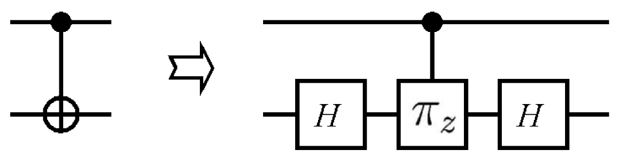
Assuming the first qubit is the control qubit and the second qubit is the target qubit, the control-phase-shift of in Fig.2 can be written as
| (10) |
Each of the four terms is explained as follows. Obviously, the first term is an identity, so no pulse is needed. The second term and the third term are rotations around the axis for the control and target qubit respectively. These can be implemented using and pulses as described in Eq.(7). The fourth term corresponds to the free evolution under spin-spin coupling between the control and target qubit. This can be implemented as a delay of , where is the spin-spin coupling constant. In summary, the NMR pulse sequence for a CN gate is as follows:
| (11) | |||||
2.3 Quantum Switch
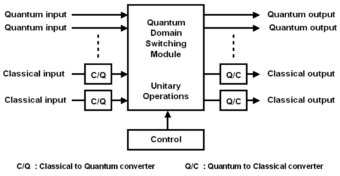
In this experiment, the architecture of a quantum switch [13] is implemented, as depicted in Fig.3. The I/O ports of a quantum switch can be configured to carry either quantum or classical information. For those I/O ports that carry classical information, the incoming bit stream has to be converted into qubits for further processing. This can be done by a classical to quantum converter (C/Q) which converts ’0’ into and ’1’ into . All qubits are then permuted using unitary operations. After the permutation, all qubits are converted back into their classical form by a quantum to classical converter (Q/C).
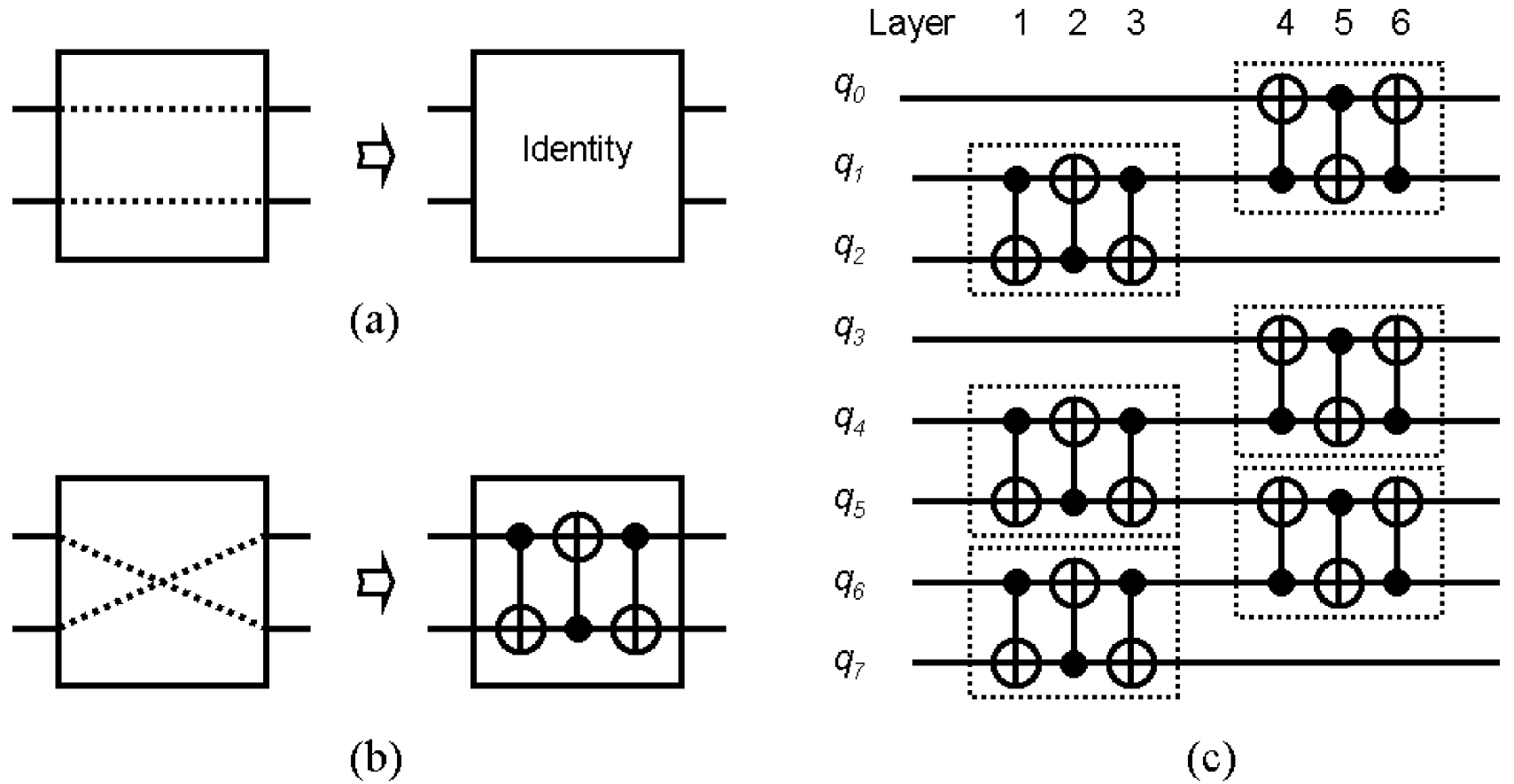
Following this principle, a 22 quantum switch is shown in Fig.4(a) and Fig.4(b). If the quantum switch is in the bypass mode, no operation is needed. However, for a 22 quantum switch in the cross mode, three CN gates (with the middle one up side down) are used to switch the quantum state. Note that an nn quantum switch is not constructed by concatenating 22 switch elements as in classical Clos networks. Instead, an nn quantum switch is implemented using (constant) layers of CN gates, which is an important feature of this architecture. An example of an quantum switch is shown in Fig.4(c).
3 Experimental Realization
With a Bruker Avance DMX-500MHz NMR system, carbon-13 labelled chloroform (13CHCl3) in d6-Acetone at room temperature is used as our switching fabric. The 1H and 13C atoms in chloroform are used as the information carrier. In this experiment, channel 1 is setup for 1H and channel 2 is setup for 13C. The observed channel is the proton spectrum in channel 1. The C/Q is done by RF pulses to convert the classical information into quantum states. The pulse sequences for a quantum switch in the cross mode are formed by three CN gates as in Eq.(11), with the second CN gate up side down.
In this experiment, the power of the pulses are set at 3.00 dB for channel 1 (1H) and -3.00 dB for channel 2 (13C). The duration for a pulse is 9.5 s for channel 1 and 12.6 s for channel 2. Since the rotation of a single qubit quantum operation is proportional to the product of the power and duration of the RF pulses, a simple calculation will give the duration for a pulse and pulse. The free evolution (under the control of spin-spin coupling) is the source of conditional logic in quantum computing. The spin-spin coupling between 1H and 13C is measured to be 215 Hz. As a result, the duration of a free evolution of is calculated as 1.165 s, and a rotation is 2.33 s, twice the number for a rotation. These parameters are assigned to the D, P, and PL arrays in Bruker’s pulse program.
In an NMR experiment, usually a number of identical scans are carried out to improve the signal to noise ratio (at the expense of taking more time to carry out the experiment). This parameter is called NS (Number of Scans). A typical NS value for a standard chemical experiment is on the order of to , depending on the density of the sample. Also, to allow the sample to reach a steady state, several dummy pulses are applied before the real pulses, without collecting the NMR signal. This parameter is called DS (Dummy Scans). A typical DS value is around to . Since an enriched sample is used in this experiment, the NS and DS are set up as and respectively.
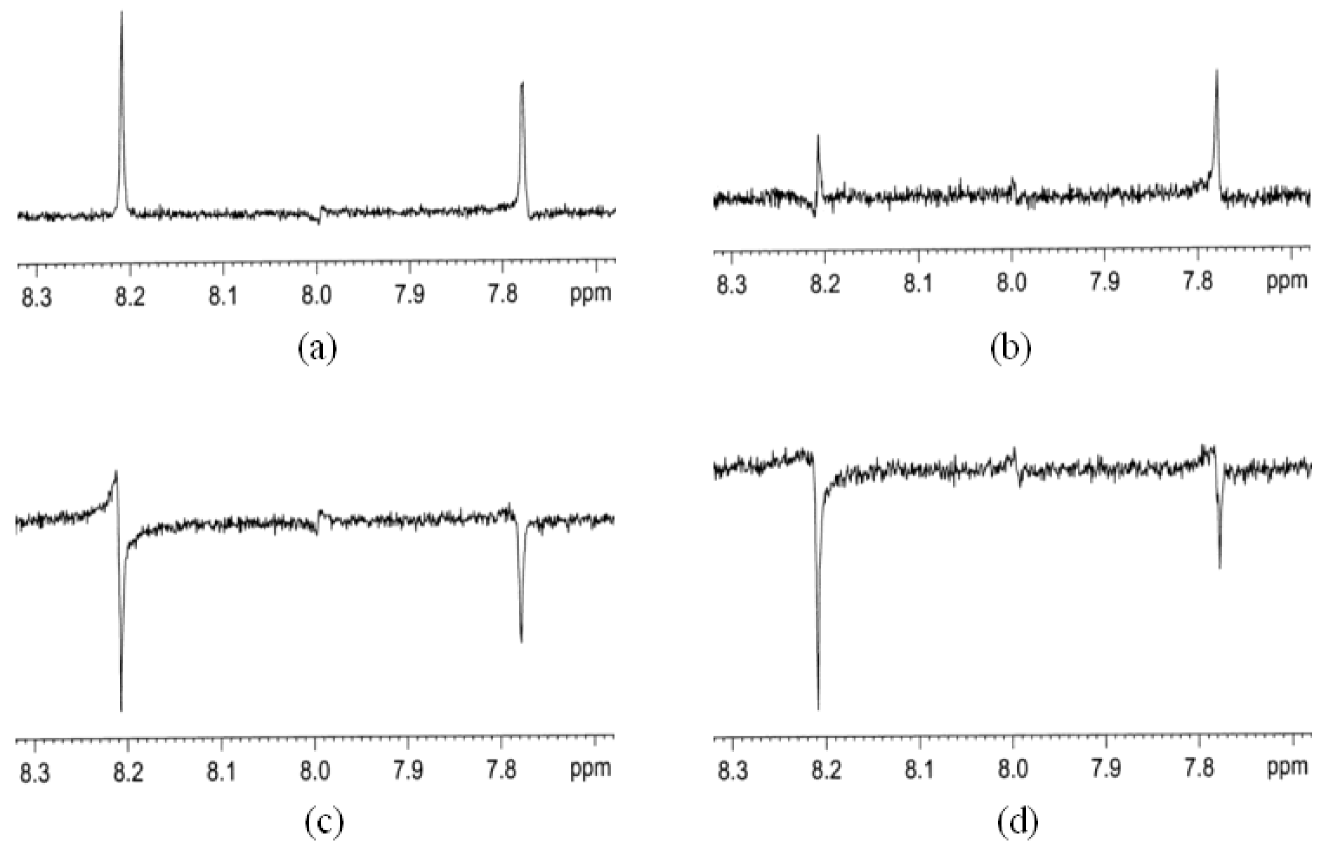
Other acquisition parameters include the Time Domain size (TD) which specifies the total number of points to be collected in the time domain, and the FID Resolution (FIDRES) which indicates the frequency range between each point. In this experiment, the TD is 32768 and the FIDRES is 0.305176 Hz. As a result, with an observed Spectral Width (SW) of 10000 Hz, the acquisition time is 1.63845 sec. After the data acquisition and post-acquisition processing (especially phase correction), the result for a quantum switch in cross mode is shown in Fig.5.
4 Conclusion
In this paper, we demonstrate an experimental realization of a quantum switch using nuclear spins and magnetic resonant pulses. The implementation of a quantum switch once again shows us a significant possibility of applying microscopic physics to classical engineering problems. In our experiment, the NMR technology provides with us a versatile control mechanism which can be used to improve the performance of digital switching. Although noise, loss of coherence and manufacturing issues are still bothering scientists, judging from the technological evolution in the past few decades, we believe there will be tremendous technical progress in the near future.
References
- [1] D. Deutsch and R. Jozsa, ”Rapid solution of problems by quantum computation,” Proc. Roy. Soc. Lond. A, vol.439, pp. 553-558, 1992.
- [2] P. Shor, ”Algorithms for quantum computation: discrete logarithms and factoring,” in Proc. of the 35th Annual IEEE Symposium on the Foundations of Computer Science, 1994, pp. 124-134.
- [3] L. Grover, ”A fast quantum mechanical algorithm for database search,” in Proc. of the 28th Annual ACM Symposium on the Theory of Computing, 1996, pp. 212-219.
- [4] J. Cirac and P. Zoller, ”Quantum computation with cold trapped ions,” Phys. Rev. Lett., vol. 74, pp. 4091-4094, 1995.
- [5] Q. Turchette, C. Hood, W. Lange, H. Mabuchi and H. Kimble, ”Measurement of conditional phase shifts for quantum logic,” Phys. Rev. Lett., vol. 75, pp. 4710-4713, 1995.
- [6] N. Gershenfeld and I. Chuang, ”Bulk spin resonance quantum computation,” Science, vol. 275, pp. 350-356, 1997.
- [7] D. Loss and D. DiVincenzo, ”Quantum computation with quantum dots,” Phys. Rev. A, vol. 57, pp. 120-126, 1998.
- [8] B. Kane, ”A silicon-based nuclear spin quantum computer,” Nature, vol. 393, pp. 133-137, 1998.
- [9] I. Chuang, L. Vandersypen, X. Zhou, D. Leung and S. Lloyd, ”Experimental realization of a quantum algorithm,” Nature, vol. 393, pp. 143-146, 1998.
- [10] J. Jones, M. Mosca and R. Hansen, ”Implementation of a quantum search algorithm on a quantum computer,” Nature, vol. 393, pp. 344-346, 1998.
- [11] I. Chuang, N. Gershenfeld and M. Kubinec, ”Experimental Implementation of Fast Quantum Searching,” Phys. Rev. Lett., vol. 80, no. 15, pp. 3408-3411, 1998.
- [12] L. Vandersypen, M. Steffen, G. Breyta, C. Yannoni, M. Sherwood and I. Chuang, ”Experimental realization of Shor’s quantum factoring algorithm using nuclear magnetic resonance,” Nature, vol. 414, pp. 883-887, 2001.
- [13] I-Ming Tsai and Sy-Yen Kuo. ”Digital Switching in the Quantum Domain,” IEEE Trans. Nano., vol. 1 no. 3, pp. 154-164, 2002.
- [14] D. DiVincenzo, ”Two-bit gates are universal for quantum computation,” Phys. Rev. A, vol. 51(2), pp. 1015-1022, 1995.
- [15] A. Barenco, ”A universal two-bit gate for quantum computation,” Proc. Roy. Soc. Lond. A, vol. 449, pp. 679-683, 1995.
- [16] A. Barenco, C. Bennett, R. Cleve, D. DiVincenzo, N. Margolus, P. Shor, T. Sleator, J. Smolin, and H. Weinfurter, ”Elementary gates for quantum computation,” Phys. Rev. A, vol. 52(5), pp. 3457-3467, 1995.