Further quantum-gate methods using selective displacement of trapped ions
Abstract
We consider quantum gates for trapped ions using state-selective displacement of the ions. We generalise earlier work in order to treat arbitrary separations between the traps. This requires the impact of anharmonicity arising from the Coulomb interaction to be estimated. We show that its effects are always small enough to allow high fidelity. In particular, the method can be applied to two ions in the same trap. We also show that gates between non-neighbour ions, and hence a Toffoli (three-qubit controlled-NOT) gate, can be achieved. We discuss how the gate can be applied to logical qubits encoded in the decoherence-free-subspace , where each pair of ions stores a single qubit. We also suggest alternatives to the spin-echo method to suppress unwanted terms in the evolution.
pacs:
03.67.-a, 42.50.-pI Introduction
This paper discusses the implementation of quantum logic gates in trapped ions, using a mechanism introduced by Cirac and Zoller in Ref. ions1 , in which the ions are displaced by a state-selective force, and acquire state-dependent phases from their Coulomb interaction. In a previous paper ions3 we discussed in detail the realization of a two-qubit phase gate
implemented between two ions confined in separate traps. When this is the gate which is equivalent to the controlled-NOT gate () up to single-qubit Hadamard rotations , where and are the Pauli and matrices. In this paper we extend the scheme of the two-qubit phase gate in several ways.
First, we present some methods relevant to the two-qubit phase gate. These are the use of different laser frequencies and/or switching force directions to eliminate undesired rotations, and the application of the gate to manipulate logical information encoded in a simple decoherence-free subspace.
Next, we consider the three-qubit phase gate (controlled-controlled- gate) whose effect is
| (2) |
where . This gate is equivalent to the Toffoli gate (controlled-controlled-NOT) in the sense that it suffices to add two single-qubit Hadamard rotations to obtain the Toffoli gate. The combination of with the Clifford group (generated by ) is a universal set for quantum computation. In this respect is similar to . Both and are used in networks to achieve fault-tolerant implementation of a universal set of gates on qubits encoded in quantum error correcting codes chuang ; steane04 . They are therefore desirable features of any quantum computing system. We study the problem of how to use the state-selective displacement of trapped ions (the “pushing” method) to achieve the transformation in Eq. (2) with three ions in adjacent microtraps. Our solution involves a standard decomposition of into five two-qubit gates (two controlled-NOT and three controlled-phase ). In this decomposition, one of the two-qubit gates is between non-neighbouring qubits. The interesting feature of the pushing method under discussion is that this gate between non-adjacent ions can be achieved without the need to rearrange the ions or swap the quantum information between them.
Finally, we extend the discussion of two-ion gates to the case where the ions are much closer together than was previously assumed. In this regime the Coulomb interaction introduces non-negligible anharmonicity in the confining potential. We quantify this effect and show how the anharmonicity influences the sensitivity of the gate to thermal motion of the ions. This more general treatment includes the case where two ions are confined in the same trap. We find that the effect of anharmonicity remains small even in this limit, and therefore the gate remains comparatively insensitive to thermal motion.
II Two-qubit phase gate
In this section we briefly discuss the two-qubit phase gate considered in Refs. ions1 ; ions2 ; ions3 , in order to give the background to the rest of the paper.
Let us consider a system of two interacting qubits. Suppose the evolution is of the form
| (3) |
where are states in the computational basis . The phases have values arising from the internal energy of each qubit, and the interaction energy. We wish to obtain a two-qubit phase gate, which produces an overall phase if and only if both qubits are in the logical state , that is
| (4a) | |||||
| (4b) | |||||
In order to obtain this we next apply local operations (single-qubit rotations) on both qubits
| (5) |
where we will assume
| (6a) | |||||
| (6b) | |||||
The sequence corresponds to the phase gate (4) if the following set of algebraic equations is satisfied
| (7a) | |||||
| (7b) | |||||
| (7c) | |||||
where the overall phase of the gate is given by
| (8) |
Eqs. (7) are three independent equations in four independent parameters . This means we can choose one parameter. Let us choose . Then, using Eqs. (7), we get for the other three parameters
| (9a) | |||||
| (9b) | |||||
| (9c) | |||||
and the overall phase reads
| (10) |
When we have the quantum logic gate which is equivalent to the controlled-NOT gate .
Next we briefly discuss the spin-echo or -pulse method which can be used to suppress an unwanted term in the evolution and thus improve the fidelity (precision) of the gate. This method relies on the assumption that we generate the same unwanted term in two successive operations . A pair of pulses on qubits 1 and 2 produces the effect
| (11) |
where
| (12) |
We replace the original gate sequence by and obtain
| (13a) | |||||
| (13b) | |||||
where is defined in Eq. (10) and the single-qubit rotations are
| (14) |
with
| (15) |
where we have dropped a global phase . From Eq. (13), the logical state is rotated during the new gate sequence by , so to achieve the desired evolution in Eq. (4) we require . This means that in the new sequence each operation will typically (assuming a linear dependence in the gate time) be applied for a time half as long as in the original sequence .
II.1 Fidelity
The calculation of fidelity of a two-qubit phase gate was discussed in detail in Refs. ions3 ; ions4 . Here we briefly present the results, in order to clarify the importance of the -pulse method, which will be extended to a three-ion gate in Sec. IV.
We consider a general initial state
| (16) |
and calculate the fidelity minimised over , i.e. we consider a “worst-case” initial state of the qubits. The fidelity of a two-qubit phase gate corresponding to the pulse sequence can be expressed then as
| (17) |
where is a random departure of the phase from its expected value and denotes averaging over all degrees of freedom of the system. For trapped ions it corresponds to averaging over all ion trajectories.
The fidelity of a two-qubit phase gate corresponding to the sequence (i.e. phase gate with pulses) can be written as
| (18) |
where and . Whenever and (achieved by applying the pulses), we obtain a significant improvement in the fidelity of the phase gate using the pulses, that is .
II.2 Implementation on ions in microtraps
Consider two ions confined in two separate harmonic potentials (microtraps), with a logical-state-selective and time-dependent external force acting on both ions. In the semiclassical approach (trajectories of the ions are considered to be classical) the Hamiltonian of the system is
| (19) |
where
| (20) | |||||
where the two bare (empty) microtraps with a trapping frequency are separated by a distance , is the ion mass, and are coordinates (trajectories) of ions 1 and 2 corresponding to their internal states and , and are momenta of the ions, and is the equilibrium distance between the ions () minimizing the total confining potential (potential of microtraps + Coulomb repulsion). We denote , where is the ion charge and is the permittivity of vacuum. Finally, is a logical-state-selective () and time-dependent force which displaces the ion only when it is in its logical (internal) state . The parameters and are associated with the potential (introduced by the displacing forces and ) which the ions experience when they are in their equilibrium positions () in the microtraps.
The dynamics of the ion system during the pulse are governed by the evolution operator
| (21) |
where denoted the Dyson time-ordering operator, and the Hamiltonian is defined in Eq. (19). The integration is carried out over a time interval , where we will assume that , , , where describes the duration of the time interval on which the pushing force is applied. This assumption will become clear when we choose the time profile of the force later on in this section. Then, the corresponding evolution is
| (22) |
where
| (23) |
The overall phase in Eq. (10) can be written (after a coordinate transformation and ) as
| (24) |
where
| (25) |
This means that the overall phase of the phase gate is determined only by the Coulomb interaction between the ions.
Let us define an important parameter
| (26) |
which gives the ratio between the Coulomb repulsion energy and the trapping potential. It is small () when the traps (i.e. the ions as well) are far apart and it can be large () when we move the traps close to each other. Here we consider the performance of the phase gate in the regime . In Sec. V we extend the treatment to all values of .
In the regime an ion in the internal state is displaced from its equilibrium position by
| (27) |
which also corresponds to the displacement of a single ion in a harmonic trapping potential (Appendix D in Ref. ions4 ). An ion in the internal state is not displaced because the internal-state-selective force does not act on it. Thus, in the regime we can write for the displacement of an ion , where . Then, it can be shown ions3 ; ions2 that the overall phase of the two-qubit phase gate in Eq. (10) is with
| (28) |
where we assumed a Gaussian time profile of the force, , introduced , and denoted . Then it follows from Eq. (27) that . This means that the displacement is measured in units , where is a dimensionless parameter.
The time for which the force needs to be applied is to be calculated from the condition (i.e. when the phase gate is equivalent to the controlled-NOT gate). In practice, the internal-state-selective force will be produced in a non-resonant laser beam (dipole force) with , where is the laser intensity, and is detuning from a driven atomic transition . For convenience we will treat the case where the logical state is not coupled to the laser, i.e. ensuring the state selectivity of the force. The extension to the case where both logical states experience a non-zero but different force is straightforward.
II.3 Cancellation of single-qubit rotations
The -pulse method (spin-echo) improves the fidelity of the phase gate by cancelling some single-qubit rotations which may be imprecise. Here, we propose two alternative ways to achieve the same effect without using any pulses.
The phases in Eq. (3) have a structure ions4
| (29) |
where are constants of order one (), we have typically , and we already know from the last paragraph in the previous section that .
The second term in Eq. (29) is of order one because this term produces the two-particle phase (28), and the gate time is chosen to ensure this phase is or . With , which it will be seen later is a reasonable value, the first term is of order .
When the laser intensity fluctuates it causes the value of to fluctuate as well. Let us assume, for example, 1% laser intensity fluctuations. Then the first term in Eq. (29) produces an uncertainty of order ten, which is enough to completely spoil the gate. If this can be suppressed then the gate will work since the second term has a much smaller uncertainty. We note that the combination
| (30) |
achieves the cancellation while preserving the term which is needed for the gate. To obtain this cancellation, we can use two pulses with opposite signs for the term but the same sign for the term. The -pulse method discussed above achieves this by swapping the sign of . An alternative approach is to swap the sign of . Since this can be done by using two successive pulses with opposite detuning . This is our first suggestion. We thus replace the spin-echo pulse sequence with the sequence , where () is the pulse with blue detuning (red detuning).
We showed in Ref. ions3 that the main contributions to are from the Coulomb energy and the light shift (AC Stark shift) produced by the laser field providing the dipole force. We there derived the condition for these to be equal and opposite (so called “sweet spot”).
We next consider how to cancel them each separately. It is possible to make the contribution from the light shift zero by a judicious choice of laser polarization, such that the two internal states and experience equal light shifts but different forces dalibard89 ; wineland03 . Only the Coulomb contribution then remains. This can be cancelled by applying the force in two successive pushes in opposite directions. The linear term in Eq. (29) then cancels, while the term remains.
In all these methods, the cancellation takes place as long as the laser intensity is the same for the two closely-spaced pulses. The gate remains sensitive to intensity changes between one pulse and its partner in a given pair, but is much less sensitive to changes in laser intensity between one pulse-pair and another.
Avoiding the spin-echo method is advantageous since the single-qubit -pulses it requires may be slow or imprecise. However there are practical problems in all the methods. Switching of the detuning may be technically difficult since can be of order GHz. Switching the force direction is not convenient in a travelling wave configuration where the force on each ion arises from the transverse profile of a single focused laser beam, however it can be done conveniently in a standing wave configuration by changing the relative phase of the two travelling waves forming the standing wave wineland03 .
III Decoherence-free subspace
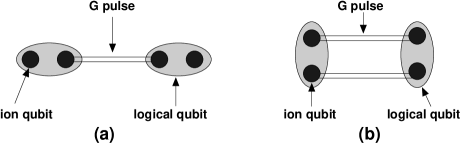
Several advantages may be obtained by encoding logical qubits not in single ions but in pairs of ions, in the decoherence-free subspace (DFS) spanned by
| (31) |
Here the subscript refers to logical states in the subspace, the kets without subscript refer to physical states of the trapped ions. This concept has been discussed in the context of trapped ions in Ref. kiel02 . The advantages arise from the fact that the two logical states evolve in the same way under any influence which causes the same phase change of relative to in both ions, therefore the logical information is completely protected from such influences. An example is a change in the magnetic field on both ions together, or a phase drift of the lasers used to implement the operations.
We will next present two methods to implement the controlled-phase gate in the DFS. The required evolution is
| (36) |
First, consider two pairs of ions arranged along a line as in FIG. 1a. They may be all in separate microtraps, or with one or more in the same trap. All we need to do to achieve the desired gate is apply the pushing method to the central two ions. The presence of the other ions has a small influence on the distance through which the pushed ions are displaced, and their Coulomb interactions contribute to the total phase. However, this simply changes by a factor of order one the time required to achieve the desired phase , but it does not introduce sensitivity to thermal motion. We thus obtain the evolution
| (41) |
To obtain the phase gate in Eq. (36), the Pauli operation is then applied to the second logical qubit.
It may be objected that the operation just described lacks symmetry in the way the controlling apparatus interacts with the ions in a given pair, and therefore it is against the spirit of the DFS concept. However, the joint state of the ions remains at all times in the DFS, and the mechanism of the pushing force (such as a far off-resonant dipole force) does not rely on the need for the very precise frequency matching which the DFS is designed to avoid. Therefore the need for very precise frequency matching (or magnetic field control) is still avoided.
An alternative and more symmetric way to implement the gate in the DFS is shown in FIG. 1b 111The original idea comes from T. Calarco.. By pushing the ions as shown, before any single-qubit rotations are added the evolution is
| (46) |
where are the same phases as in Eq. (3). Recalling Eq. (10), the overall phase for the evolution of the logical qubits is
| (47) | |||||
Therefore the gate is obtained in a time half that required for single ions in the same conditions.
The method of FIG. 1b may be more difficult to realise in practice, owing to the two-dimensional rather than one-dimensional configuration of the ions. However, it has the advantage that the cancellation of unwanted phases in Eq. (29) takes place automatically without any need for pulses or switched detunings. This also means the “sweet spot” method discussed in Ref. ions3 is not needed.
IV Non-neighbour ions and Toffoli gate
IV.1 Principle
We now consider a system of three qubits. First we present an analysis of the general requirements along similar lines to that used for two qubits in Sec. II. Suppose a system of three interacting qubits evolves as
| (48) |
where denotes a joint logical state of three qubits with . Our aim is now to realize a three-qubit phase gate
| (49a) | |||||
| (49b) | |||||
that is the gate which produces an overall phase if and only if all three qubits are in the logical state . The three-qubit phase gate can be obtained when we apply single-qubit rotations after the operation , that is
| (50) |
where
| (51a) | |||||
| (51b) | |||||
| (51c) | |||||
The sequence will correspond to the three-qubit gate if the following equalities are satisfied
| (52a) | |||||
| (52b) | |||||
| (52c) | |||||
| (52d) | |||||
| (52e) | |||||
| (52f) | |||||
| (52g) | |||||
where the overall phase reads
| (53) |
In Eqs. (52) we have seven equations in six independent parameters (), but the equations are not all linearly independent. By combining them we obtain
| (54a) | |||||
| (54b) | |||||
| (54c) | |||||
These are conditions on the evolution (48) which will have to be satisfied if the Toffoli gate (the three-qubit phase gate, to be precise) is to be realised.
When we apply Eqs. (54), then Eqs. (52e)–(52g) can be expressed as linear combinations of Eqs. (52a)–(52d). This means that the original system (52) is now reduced to four independent equations and six independent parameters. Therefore, we can choose two parameters and calculate the rest. Let us pick . We then get and
| (55a) | |||||
| (55b) | |||||
| (55c) | |||||
where the overall phase is
| (56) |
We can also introduce -pulses in order to cancel unwanted terms. We replace the sequence by , where denotes a pulse applied on all three qubits. An analysis along similar lines to the above implies that the three-qubit phase is now given by
The single-qubit rotations take the same form as in Eqs. (51), except that now we have , and
| (58a) | |||||
| (58b) | |||||
| (58c) | |||||
There is again a set of conditions to be satisfied if the three-qubit phase gate with pulses is to be realized. They are
IV.2 Implementation on ions in microtraps
The Hamiltonian for the system of three ions in three separate microtraps is
| (60) |
with
|
|
||
where we introduced a notation , , and , , , and we applied a coordinate transformation , and assuming that the ions are at sites , and with . Then the three-particle dynamical phases read
| (62) |
The structure of the Hamiltonian in Eq. (IV.2) allows us to write for the overall phase
| (63) |
where
| (64) | |||||
It follows from Eq. (63) that the overall phase is determined again only by the interaction phases rather than by the total phases . However, in contrast to Eq. (25) this time we have to consider three pairs of mutual Coulomb interactions.
We need to verify whether Eqs. (54) can be satisfied for the system of ions in microtraps. In the adiabatic approximation () and for we can write the trajectories of the ions in the form
| (65a) | |||||
| (65b) | |||||
| (65c) | |||||
where denotes the state-selective displacement of the ion (Eq. (27)), and corresponds to thermal oscillations of the ion in the microtrap. The adiabatic regime means that the state-selective pushing force is applied on a time scale much longer than an oscillation period of the ions in microtraps. We assume first of all that state-dependent forces of the same magnitude and the same pulse time are applied to all three ions. Then, the analysis of Eq. (64), using the methods of ions3 ; ions4 , shows that the three-particle phases take the form
| (66) |
where is defined in Eq. (28), , and we dropped terms of order because we have typically .
When we apply the gate pulse on three ions for a time , followed by the single-qubit rotations , we obtain
| (71) |
which corresponds to , where is the phase gate in Eq. (I) between ions and . This means that the single pulse on all three ions simultaneously (followed by single-qubit rotations ) produces three two-qubit controlled-phase gates. The two-qubit phase of the gate between the outermost pair of ions is , rather than , because the separation of those ions is and the two-qubit gate phase is proportional to the inverse cube of the separation.
To obtain the simple three-qubit phase gate from Eq. (71) we apply a network as in FIG. 2. A sequence containing two controlled-NOT and two controlled-phase gates on adjacent ions causes the overall evolution to be
| (76) |
which is a three-qubit phase gate for (or an integer multiple of ). The controlled-NOT gates can be obtained from the two-qubit phase gate plus Hadamard rotations (or pulses).
Note that when , the operation (71) is . In other words, we have simply a two-qubit phase gate between the outermost pair of ions. In this case the force on the central ion is redundant, i.e. the same result would be obtained with laser beams pushing only the two outermost ions. This also shows that the network of FIG. 2 is a standard decomposition of as presented in Ref. barenco95 .
The implementation of the phase gate including a spin-echo by pulses is also completed by the same network (FIG. 3).


We note that in principle, two-qubit gates between pairs of ions even further apart could also be implemented simply be pushing the relevant pair of ions, without the need first to make them adjacent.
IV.3 Speed of the gate
Next we estimate the speed of three-qubit phase gates with ions in microscopic traps. We will consider single-qubit gates ( pulses, rotations) to be fast compared to multi-qubit gates. This is typically the case for trapped ion qubits. Therefore we only need to add together the times for two-qubit and three-qubit logic gates on the ions. We assume that these are all produced by the state-selective pushing method under discussion.
There are two different assumptions about the speed of the operations which are both physically sensible. First, we may assume that all operations involve pushing forces of the same magnitude. In this case the time required to produce the two-qubit phase gate between the outermost ions is eight times longer than the time to produce the same gate between adjacent ions. On the other hand, we might assume that the forces are always adjusted in magnitude so that the gate duration is limited by the adiabatic criterion . In this case the gate between outermost ions has the same duration as the same gate between adjacent ions, but requires larger forces.
With the former assumption (forces of given magnitude), the total time required for the whole network, including and the two-qubit gates, is
| (77) |
where is the time required for a gate (i.e. ) between adjacent ions. The duration of the pulse is because we need . The duration of the final gate is since .
With the other assumption (all gates of duration ), the total time is .
The same conclusions apply to the three-qubit phase gate with pulses in FIG. 3, except that now each of the two pulses is applied for a time (instead of ), and the fidelity of the gate is higher.
V Two-qubit Phase gate in general
In Ref. ions3 we discussed the dynamics of a two-qubit phase gate with ions in microtraps in the regime , that is when the two microtraps were sufficiently far apart. In what follows we will re-examine the dynamics of the ion system outside this regime, i.e. . We will use a more general approach compared to the one in Ref. ions3 . The aim is to understand the phase gate for all values of , and especially for the case of two ions in the same trap, where .
To this end it is useful to write the Hamiltonian in Eq. (20) in a new coordinate system
| (78a) | |||||
| (78b) | |||||
where is a centre-of-mass coordinate of the ion system, is a relative excursion of the ions from their equilibrium positions, and correspond to logical states of ion qubits . Then, the Hamiltonian splits into a centre-of-mass and a relative-motion part
| (79) | |||||
where we have introduced , , , and . The potential-energy terms of the two ions in a joint internal state are
where we denoted (i.e. the difference between the separation of ions loaded in the traps and the separation of the centres of bare traps), and we assumed since .
The ion separation can be calculated from the equilibrium when no force is applied, that is
| (81) |
giving
| (82) |
where . Using Eq. (82) and substituting into the expression of in Eq. (26), we find that is a function of a single variable . The function is monotonic and there are two limiting cases. (i) When (which corresponds to , i.e. microtraps are far apart), we get . This means that , and . (ii) On the other hand, when (corresponding to , i.e. the two separate microtraps overlap completely and we end up with two ions in a single linear trap), we get , which is also the maximum value of .
Substituting into Eq. (26) gives
| (83) |
which is the standard expression of the separation of two ions in the same harmonic trap. We refer to this case as the case of a “linear trap”, since typically one chooses a linear geometry in the Paul trap in order to avoid micromotion when more than one ion is trapped. Note that whereas in separate microtraps we could adjust the trapping frequency and ion separation independently, in a linear trap (i.e. two ions in the same trap) they are mutually dependent.
V.1 Anharmonicity
In the discussion about ions in two separate microtraps in Sec. II, the results were valid in the regime . Next we examine the meaning of this condition, and show how it can be substantially relaxed. This is necessary in order to allow the gate to be implemented for two ions in the same trap, since then .
We can expand the Coulomb term in Eq. (80b) in a Taylor series owing to , giving
| (84) | |||||
where we denoted , used the definition of in Eq. (26), applied Eq. (81), and dropped a constant term . This means that in the regime the effective trapping potential becomes anharmonic. We need to find out how the anharmonicity affects the centre-of-mass and the relative motion of the ions.
V.2 Dynamics
Eqs. (80) and (84) lead to the equations of motion
| (85a) | |||||
| (85b) | |||||
where , with . In the following we assume for convenience that the state-selective-force acts only when the ion is in its internal state , so that , , where . Using Appendix D in Ref. ions4 the solution of Eq. (85a) in the adiabatic regime () is
| (86) |
with
| (87a) | |||||
| (87b) | |||||
where we used Eq. (27), and () is the oscillation energy (initial motional phase) of the centre-of-mass motion of the ions.
There is no analytical solution of Eq. (85b). However, owing to the fact that the anharmonicity is small even for . Therefore, we can estimate the solution in the adiabatic approximation () as
| (88) |
with
| (89a) | |||||
| (89b) | |||||
where arises from the condition , and refer to the oscillation energy and an initial motional phase of the relative motion of the ions, and is to be discovered.
When only one ion is in the state , that ion is displaced by the quantity imposed by the force in Eq. (27). It follows from Eq. (89a) that when this is also the change in the relative separation, i.e. the other ion hardly moves besides random thermal oscillations. However, in the regime the ions are close enough to be strongly coupled. Then the other ion moves as well and the net result is that the relative displacement is reduced by a factor .
The main consequence of anharmonicity is the extra contribution to the relative motion of the ions in Eq. (89b). We no longer have the special property of a harmonic potential that the average excursion under free oscillatory motion is zero (when averaged over a large or integral number of oscillations). Instead the average is . We do not have an analytical solution and so we must estimate . As an estimate we use the average of the two turning points of the motion (at given energy) in the anharmonic well, i.e. , where and are the two roots (closest to the equilibrium point ) of the equation
| (90) |
where is the anharmonic potential defined in Eq. (84), and is thermal energy of the relative motion of the ions in Eq. (89b). We expect this estimate to be good up to a numerical factor of order one. By obtaining the two roots and expanding as a Taylor series in , we find
| (91) |
Note that the influence of on the phases appearing in the quantum logic gate arises only from that part of which depends on and , the rest will merely add a global phase. A numerical solution of the equations of motion confirmed the main points of this estimate. It was found that typically underestimates by a factor approximately six.
In order to calculate the dynamical phases in Eq. (23) it is crucial to include both the centre-of-mass motion and the relative motion, in particular because the two-qubit phase is found to arise from a difference between the two contributions, associated with the fact that . By substituting Eqs. (86) and (88) into the Hamiltonian (79) we determine the dynamic phases in Eq. (23) and hence obtain the overall phase in Eq. (10). The result is
| (92) |
where is given by Eq. (28).
In the limit when and we obtain as before. The main effect of bringing the traps together is to introduce the factor . The (small) term in in Eq. (92) is a surprise since it survives even when , and therefore it should have been present in the earlier calculations. It arises from the fact that the kinetic energy of the vibrational motion depends on where the ion is in the harmonic well, and we now allow for the fact that in all kinetic energy terms whereas previously we did not.
V.3 Phase gate in a linear trap
Let be the overall two-qubit phase from Eq. (92) in the case of two ions in the same linear ion trap (). Then
| (93) |
If there is a sufficient force available (represented by ), then the gate time is limited by the criteria that (i) the ions are not displaced too far (), and that (ii) the adiabatic conditions following from Eqs. (86) and (88), that is and , hold. Typically, the latter is the limiting condition, and it is sufficient to choose because to be precise what we require in practice is rather than . It follows that for a given value of to achieve a desired overall phase the pushing force is smaller when the ions are in a linear trap () compared to when they are in two separate microtraps (). The ratio is
| (94) |
This can be useful to reduce photon scattering (see below).
The infidelity of a two-qubit phase gate for ions in two separate microtraps with was discussed in detail in Ref. ions3 . The dynamics when we consider general was presented in Sec. V. This permits us to make a direct comparison between the case when the ions are in separate traps () and in the same trap (), and thus carry over the results of the previous study in Ref. ions3 to the present one.
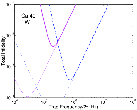
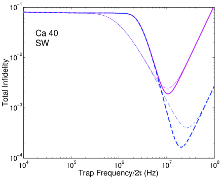
We assume the state-selective pushing force is the optical dipole force produced by an intense laser beam (see the last paragraph in Sec. II.2) in either the travelling-wave (TW) or the standing-wave (SW) configuration. There are two main contributions to the total infidelity of the gate: (i) thermal averaging and (ii) photon scattering.
Two types of thermal averaging take place. These are the averaging over the dynamic phases (), and the averaging over the spatial dependence of the pushing force (). We show in Appendix A that the contribution is of a similar order of magnitude for ions in separate traps and in the same trap. We showed in Ref. ions3 that the contribution dominates for ions in separate traps when the waist of the laser beam is (TW), or the laser wavelength is (SW). It follows that the same conditions cause to dominate for ions in the same trap.
The averaging over the spatial profile of the force () is associated with the thermal motion of either ion with respect to the laser field illuminating it. We assume for the sake of argument that for the thermal oscillations of two ions in the same trap, the centre-of-mass mode () and the breathing mode () have the same temperature. Part of the random phase associated with thermal motion may be cancelled by a common-mode rejection, but to be cautious here we will ignore that possibility and therefore we overestimate the infidelity. In this case the infidelity associated with process is approximately the same as calculated in Ref. ions3 for given values of trap frequency , temperature and laser parameters. We assume the spin-echo sequence ( pulses) is used, so we have two gates each with , and we add their two infidelities. For travelling wave excitation with Gaussian laser beams (each ion illuminated by a separate beam) the resulting infidelity is eq1
where , is the trapping frequency, , is the size of the waist of the laser beam, and is the position of the ions in the profile of the laser beam. Placing the ions at offers a useful improvement in the performance of the gate.
For standing wave excitation (i.e. the pair of ions positioned in an optical standing wave along ) we have eq2
where , is the the angle between two laser beams forming the standing-wave field, is the ion position in this field, and we assumed that the ions are placed at which minimizes the infidelity and simplifies its expression.
The expression for the number of scattered photons during the gate operation in a linear trap is derived in the same way as the result for ions in separate traps in Ref. ions3 , except that now we consider , where we assume the spin-echo sequence (hence ) and we add the numbers of scattered photons in the pair of gates. Treating the electronic transition giving rise to the dipole force by a two-level atom model, the result for travelling-wave excitation is
| (97) |
where is the laser power, and
| (98) |
where is the speed of light, is the ion mass, and is the laser wavelength.
For standing-wave excitation we obtain
| (99) |
where 222There is a mistake in Eq. (100b) in Refs. ions3 ; ions4 , where should read .
| (100) |
The total infidelity of the phase gate can be expressed as
| (101) |
assuming .
FIG. 4 and FIG. 5 give the total infidelity for some example parameter choices, with atomic properties appropriate to the 40Ca+ ion.
VI Conclusion
In this paper we offered further quantum-gate methods using the state-selective displacement of trapped atomic ions ions1 , and in this sense this paper complements our previous publication ions3 .
We proposed methods to suppress unwanted effects in the evolution, as an alternative to the spin-echo method. We also discussed the application of the gate to logical qubits encoded in pairs of ions (rather than in single ions) in a decoherence-free subspace.
We showed that it is possible to realize two-qubit gates between non-neighbouring ions without the need to swap the ions around or move quantum information between them. This produced an implementation of the Toffoli (three-qubit controlled-NOT) gate with three ions in three separate microtraps, where the three-qubit gate is five to eight times slower than its two-qubit counterpart.
We also showed that the original state-selective displacement method for a two-qubit phase gate with ions in separate microtraps can be extended to the case with two ions in the same trap. We analyzed the anharmonicity of the effective trapping potential, arising from the Coulomb interaction potential between ions, and found that its effects were small even in the limit of two ions in the same trap. Therefore the gate retains its attractive features (a good combination of speed and robustness), whatever the separation of the ion traps.
Acknowledgements.
This work was supported by the EPSRC, ARDA (P-43513-PH-QCO-02107-1), and by the Research Training, Development and Human Potential Program QUEST of the European Union. We would like to acknowledge helpful discussions with T. Calarco.Appendix A
We showed in Ref. ions4 that in the regime a contribution from thermal averaging to the total infidelity of a two-qubit phase gate (defined in Eq. (101)) is given by Eqs. (V.3) and (V.3). In this contribution thermal averaging over the size of the state-selective force (i.e. over the spatial profile of the force) dominates averaging over the dynamic phase (i.e. over a discrepancy between random values of in a pulse and their deterministic values in single-qubit rotations ), where the latter reads 333See Eq. (89) in Ref. ions3 .
| (102) |
In the regime of interest in this paper () we need to reconsider this conclusion on the grounds of anharmonic effects present in the system. In particular, we need to calculate the contribution to the infidelity from thermal averaging over the dynamic phases for and compare the result to the contribution from averaging over the force profile, which is the same for any value of .
Using a precise analytical expression of the overall phase in the regime we calculate that the infidelity from averaging over the dynamic phases is
| (103) |
When we use the phase condition , and choose , we obtain
| (104) |
Thus we find that the contribution arising from anharmonicity scales as , and therefore it does not dominate the infidelity. Comparing Eqs. (102) and (104), the expressions have the same functional form and a similar size. Both are small compared to Eqs. (V.3) and (V.3) when the laser beam waist or the standing wave period are small compared to the ion separation .
References
- (1) I. Cirac and P. Zoller, Nature 404, 579 (2000)
- (2) M. Šašura and A. Steane, Phys. Rev. A 67, 062318 (2003)
- (3) M. Nielsen and I. Chuang, Quantum Computation and Quantum Information (Cambridge University Press 2000).
- (4) A. M. Steane and B. Ibinson, Fault-Tolerant Logical Gate Networks for CSS Codes, e-print quant-ph/0311014.
- (5) T. Calarco, I. Cirac and P. Zoller, Phys. Rev. A 63, 062304 (2001).
- (6) M. Šašura and A. Steane, e-print quant-ph/0212005.
- (7) D. Kielpinski et al., Nature 417, 709 (2002).
- (8) See Eq. (125) in Ref. ions3 .
- (9) See Eq. (126) in Ref. ions3 .
- (10) D. J. Wineland et al., Phil. Trans. R. Soc. Lond A 361, 1349 (2003).
- (11) J. Dalibard and C. Cohen-Tannoudji, J. Opt. Soc. Am. B 6, 2023 (1989).
- (12) A. Barenco et al., Phys. Rev. A 52, 3457 (1995).