How to realize a universal quantum gate with trapped ions
Abstract
We report the realization of an elementary quantum processor based on a linear crystal of trapped ions. Each ion serves as a quantum bit (qubit) to store the quantum information in long lived electronic states. We present the realization of single-qubit and of universal two-qubit logic gates. The two-qubit operation relies on the coupling of the ions through their collective quantized motion. A detailed description of the setup and the methods is included.
Keywords:
Quantum computing, quantum bits, entanglement, single ions1 Introduction
Quantum computers (QC) are known to perform certain computational tasks more efficiently than their classical counterparts. The theoretical concept of QC is highly developed. Most well-known among the quantum algorithmsCHUANG00 is the efficient algorithm for the factorization of large numbersSHOR97 which threatens the security of the commonly used RSA-encryption scheme. Furthermore, efficient quantum algorithms exist for searching entries in an unsorted data baseGROVER97 , for simulating quantum spin systemsJANE03 , and for quantum games. As in a classical computer, errors will necessarily occur. Although the nature of errors is different in quantum mechanical and in classical computers, algorithms have been developed which can correct qubit errorsSHOR95 ; STEANE96 . World-wide efforts aim at a scalable realization of a QCARDA . Already in 1995, J. I. Cirac and P. Zoller proposed to implement a scalable QC on a string of trapped ions, where each ion’s electronic state represents a qubitCIRAC95 . Quantum gates between any subset of ions would be induced by laser-ion interactions, including the coupling of the ions to their collective quantized motionSASURA02 . Today, a number of different proposals for quantum gates in an ion based QC are known.
While the construction of a large scale QC might still be in remote future, we may already today perform experiments with a small number of qubits, bringing into reality what used to be Gedanken experiments and thus enlightening the foundations of quantum mechanics. This will serve to further extend our knowledge of the puzzling quantum theory and its borderline to classical physics, given by decoherence and the measurement processDECOHERENCE98 .
The ion-trap system itself is fully understood theoretically, and equally well its interaction with a laser field. Any kind of quantum logic gate operation may thus be predicted. Actual experiments are performed with few ions that are confined in a Paul trap, such that time scales for decoherence and for the dephasing of qubits due to fluctuations of external parameters are long as compared to the coherent qubit operation times. The detection of the ions’ internal states relies on electron shelving, leading to a detection efficiency near unity. In this kind of fully defined, text-book like setting, elementary quantum processors may be realized. Quantum logic gate operations and entangled states may be studied.
The most challenging experimental step towards achieving the CiracZoller scheme (CZ) of a QC is to implement the controlled-NOT (CNOT) gate operation between two individual ions. The CNOT quantum logical gate corresponds to the XOR gate operation of classical logic which flips the state of a target bit conditioned on the state of a control bit. Taking the basis states = {} of two qubits, the CNOT operation reads , where represents an addition modulo 2. Only if the control qubit (first entry) is in , the quantum state of the control qubit changes. Here, we present the realization of a CNOT quantum gate SCHMIDTKALER03 according to the original CZ proposal CIRAC95 .
In our experiment, two 40Ca+ ions are held in a linear Paul trap and are individually addressed with focussed laser beams. Superpositions of long-lived electronic states represent a qubit. By initializing the control and target qubit in all four basis states and performing the CNOT operation, we determine the desired truth table. To prove the quantum nature of the gate, we use a superposition state for the control qubit and generate an entangled output state.
2 Experimental setup
2.1 Levels and transitions in the 40Ca+ ion
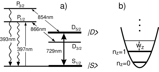
The Calcium ion (40Ca+) has a single valence electron and no hyperfine structure, see fig. 1a for the relevant levels and transitions. We have chosen 40Ca+ for several reasons: (a) The transition wavelengths for Doppler-cooling and optical pumping are well suited for solid-state and diode laser sources. (b) Long-lived metastable states ( s) allow for the implementation of qubits. (c) The narrow-line quadrupole transition can also be used to implement sideband cooling to the vibrational ground state.
We cool the ion on the S1/2 to P1/2 transition near 397 nm close to the Doppler limit. The UV-radiation is produced as the second harmonic of a Ti:Sapphire laser at 794 nm111The practicability of a grating stabilized UV-diodeHAYAS00 ; LANCESTER03 for single ion cooling and detection has been proven.. Grating stabilized diode lasers at 866 nm and 854 nm prevent pumping into the D3/2 and D5/2 states. Each of the above lasers is frequency-locked to its individual optical reference cavity using the Pound-Drever-Hall method DREVER83 . With cavity linewidths of 2-5 MHz, we reach a laser frequency stability of better than 300 kHz. Frequency tuning of the lasers is achieved by scanning the length of the corresponding reference cavities using piezo-electric actuators.
The electronic level S is identified with logic and D with logic , respectively. To perform quantum logic operations, we excite the corresponding transition with a Ti:Sapphire laser near 729 nm. The complete laser system for the qubit manipulation is described in sect. 2.4 and 2.5.
We detect the quantum state of the qubit by applying the laser beams at 397 nm and 866 nm and monitoring the fluorescence of the ion at 397 nm on a photomultiplier and on a CCD camera (electron shelving techniqueDEHMELT75 ). The internal state of the ion is discriminated with an efficiency close to 100, details of the detection are found in sect. 3.5.
It is of advantage that pure 40Ca+ ion crystals can be loaded into the trap using a relatively simple photo-ionization schemeKJAERGARD00 that relies on a two step laser excitation: A weak beam of neutral Ca is emitted by a resistantly heated ovenROTTER . Calcium atoms are excited on the transition near 423 nm by a grating stabilized diode laserGULDE01 ; ROTTER . Ionization is reached with radiation at 390 nm using a UV-diode laser or even a simple UV-light emitting diode.
2.2 Linear Paul trap
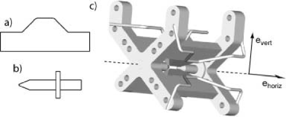
For the experiments, 40Ca+ ions are stored in the harmonic potential of a linear Paul trap. The trap is made of four blades for radial confinement and two tips for axial confinement, see fig. 2. Under typical operating conditions we observe axial and radial motional frequencies (1.2, 5.0) MHz, respectively. The trap combines good optical access with relatively high trapping frequencies, even though the trap dimensions are comparatively large. Electrically insulating parts have no direct line of sight to the ions. We attribute the low heating rate (1 phonon/50ms)ROHDE01 to the combination of a large distance between ions and trap electrodes (r0 0.8 mm) and the clean loading scheme by photo-ionization. Both tips, typically at +1kV, are positioned in the symmetry axis with high precision. Small asymmetries are compensated by applying voltages of below 200 V to electrodes which are placed at a radial distance of 30 mm from the trap symmetry axis (fig. 2c). The radio frequency (RF) 23.5 MHz is applied to two diagonally opposing blades (the other two being at 0 V). This creates an oscillating electrical quadrupole field which results in a radial trapping potential. The RF is generated by a synthesizer222Marconi Inc., Signal gen. 2019A and amplified333Minicircuits Inc., LZY-1 to 15 W. A helical -resonator (loaded Q-value 200) serves to match the capacitive load of the trap structure with the 50 output of the amplifier and to enhance the drive voltage to a few kVpp. We typically operate the trap close to the stability parameter q0.6GOSH95 . In order to avoid RF pick-up on the DC-voltage leads we use separate feed-throughs and filter the DC voltages.
The trap is mounted in a UHV housing, pumped by a Titanium sublimation and an ion getter pump444Varian Inc., Starcell 20. The residual gas pressure is below mbar.
2.3 Optical setup
The output of a Ti:Sapphire laser555Coherent Inc., 899-21 near 794 nm is frequency-doubled666Spectra Inc., Wavetrain to obtain up to 50 mW light at 397 nm. We stabilize the UV power to 1 using an AOM in front of the doubling cavity. During a gate operation on the qubit transition, any residual UV-light has to be suppressed to a maximum. As the UV-light needs to be switched faster than mechanical shutters would allow, we pass it through an AOM777Brimrose Inc., QZF-80-20, couple into a single-mode polarization-maintaining fibre888Schäfter Kirchhof Inc. and transport it to the trap. After the fiber output, the light is sent through a second AOM. Switching the RF-drive of both AOM’s yields an extinction of about . Additionally, due to the fibre, the UV-beam is spatially filtered such that its focus on the ion crystal (m, 100 W) does not cause excessive stray-light on the trap electrodes. The UV-beam leaving the second AOM is split into two beams which are superimposed with light at 866 nm and 854 nm. These beams enter the vacuum system via UV-AR coated windows, and intersect at the ion trap under angles of -22, 0 with respect to the axial trap direction, and 22, 45, respectively. The combination of both light fields is used for Doppler cooling, ion detection, and the compensation of micro-motion.
Another part of the UV-light transmitted through the fiber is controlled by a third AOM, enters along the axis of the magnetic field 22, 0, and is applied for optical pumping.
The switching of the light field at 854 nm is controlled by an additional AOM in double-pass configuration to assure on/off-dynamics of about . The laser field at 866 nm does not couple to the qubit levels and is kept on continuously.
The fluorescence of the ions at 397 nm is collected through a viewport using a large collimating lens999Nikon, MNH-23150-ED-Plan-1.5x at a working distance of 65 mm and focused onto an intensified CCD camera101010Princton Instum., Inc. I-Penta-MAX. This corresponds to a solid angle of 0.01 of . A magnification of 20 is chosen. In opposite direction, a similar lens with magnification of 7 is used for single photon counting with a photomultiplier111111Electron-Tubes Inc., P25 (PMT). We estimate an overall detection efficiency of 0.1 and 0.2 for the CCD and PMT, respectively. We typically obtain a PMT count rate of 30 kHz from a single ion, while the stray light level is below 2 kHz. The direction of the detection with respect to the trap symmetry axis is -68, 0 and 112, 0 for CCD and PMT, respectively.
2.4 Laser setup for the qubit transition
Qubit operations are performed with laser light near 729 nm, generated from a second Ti:Sapphire laser121212Coherent Inc., 899-21. To obtain a high fidelity of gate operations this laser source has to be stabilized in frequency and intensity to a high degree. For frequency stability, we rely on a stable reference cavity. Its length stability is guaranteed by a spacer from ultra-low thermal expansion material (ULE) on which the cavity mirrors (super-mirrors with a few ppm loss and transmission, measured finesse of 2.4105) are optically contacted. For additional stability, the cavity is suspended on wires in a temperature stabilized UHV chamber. We derive a Pound-Drever-Hall error signalDREVER83 and stabilize the laser frequency with a servo bandwidth of 2.5 MHz obtaining a laser linewidth Hz ROHDE_DR . The laser intensity is stabilized using an AOM to about 1.
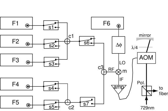
The qubit operations require laser pulses with well defined phase, frequency, intensity and duration. We modulate the output of the Ti:Sapphire laser (350 mW) with an AOM131313Brimrose Inc.,TEF-270-100 (see fig. 3) in double-pass configuration. The radio frequencies and phases that are applied to the AOM transfer directly to the light field141414Due to the double-pass configuration, the modulation of laser frequency and phase is twice the applied RF modulation..
For maximum flexibility of the complex temporal pattern, we use the scheme depicted in fig. 3. Sideband ground state cooling is performed with sources F4 and F5 at frequencies resonant to the red sidebands and . The specific quantum gate sequence is composed of pulses on the carrier and blue sideband of the bus mode, driven by the sources F1 and F2, while F3 is used for the AC-Stark compensation (see sect. 3.3). The computer digital output card151515Jäger Inc., ADwin, temporal resolution 1 s, 32 channels, serves to switch the frequency sources and the digital phase shifter. F6 compensates for the drift of the laser reference cavity. The linear drift component of 10 Hz/s is determined by comparison to the atomic resonance and anticipatively corrected for. As we saturate the LO input of the frequency mixer , a small RF-transmission modulation of the phase shifter for different does not convert into a RF-intensity modulation at IF. In addition, this RF-setup allows for the generation of multi-chromatic light fields, as necessary e.g. for the compensation of the AC-Stark effect.
2.5 Single ion addressing optics
For addressing individual ions, light at 729 nm is spatially filtered and transported by an optical fibre. A two-lens telescope expands the 729 nm beam while an electro-optic deflector(EOD)212121LaserComponents Inc., ED2-730 in front of the lenses controls the beam direction. We direct this expanded laser beam (w1cm) counterpropagating to the emerging fluorescence towards the CCD, using a dichroic beam splitter and focus it onto individual ions by using the same lens222222Nikon, MNH-23150-ED-Plan-1.5x as for imaging the fluorescence light. The focused beam of up to 80 mW hits the ion crystal under an angle of 68,. The corresponding single ion Lamb-Dicke factors are and , respectively. By varying the voltage applied to the EOD we steer the focus at the ion position by more than 10m, large compared to the two-ion distance of 4.90m232323Projection of the two-ion distance of 5.29m under 22∘ for =1.2 MHz. Additionally, the high-voltage controller for the deflector can be preset to values which are selected through digital input lines. The digital signals are computer-generated by the same digital output board that controls the RF pulses. Between different addressing positions, we typically leave a settling time of 15 s. The determination of the spatial resolution is discussed in sect. 3.2.
In order to provide a quantization axis and to split the Zeeman components of the S1/2 to D5/2 transition, we compensate the ambient magnetic field and generate a constant magnetic field of 2.4 G under an angle of 22, 0 which is thus perpendicular to the -vector of the addressing light field. The geometry and polarization of the light field at 729 nm allows the excitation of and transitionsROOS_DR .
3 Preparative procedures and measurements
This section addresses the methods that are used to prepare and manipulate the ions for a typical experimental sequence. In a first step, the ions are initialized in a well defined state using sympathetic sideband cooling and optical pumping (sect. 3.1). Then, the ions are individually manipulated on the qubit transition. During manipulation on the sideband frequencies, the level-shifts due to the AC-Stark effect need to be counteracted by additional laser frequencies (sect. 3.3). Finally, the individual states of the ions are detected by means of a CCD camera and a PMT (sect. 3.5).
3.1 Ground state cooling
Each experimental cycle starts with the preparation of the ions in a well defined initial state. The motional state of the two ion crystal can be described by 6 different vibrational modesJAMES98 . The axial and two radial center-of-mass modes at and coincide with the single-ion trap frequencies. The two radial rocking modes and one axial breathing mode have frequencies of and , respectively. In our experiment, we have chosen the breathing mode as the ‘bus-mode’ for the quantum gate and we therefore need to prepare it in the ground state . For the radial spectator modes, Doppler cooling is sufficient as 1242424The final temperature is close to the Doppler cooling limit if the UV light intensity is below saturation. However, the axial spectator modeWINELAND_B98 at is sideband cooled in addition to the bus-mode.
The cooling cycle starts with a 2 ms period of Doppler cooling on the S1/2 to P1/2 transition at 397 nm during which the repumping laser on the D3/2 to P1/2 line (866 nm) is switched on.
After a short period of optical pumping into the S state (typically 30s), the bus-mode and the axial center of mass mode are sequentially sideband cooled using the quadrupole transition at 729 nm ROHDE01 . We switch the 729 nm-laser to one of the two ions and subsequently perform a cooling cycle for 2 ms and 6 ms on the red sideband of the center-of-mass mode and of the bus-mode, respectively. The cooling rate is enhanced to several kHz by a quench laser on the D5/2 to P3/2 transition at 854 nm. During these periods, the -beam is repeatedly pulsed on every 2 ms to recollect atoms that have been pumped to the S state.
3.2 Addressing single ions
As explained in section 2.5, the focus position of the manipulation laser at 729 nm is controlled by the EOD.
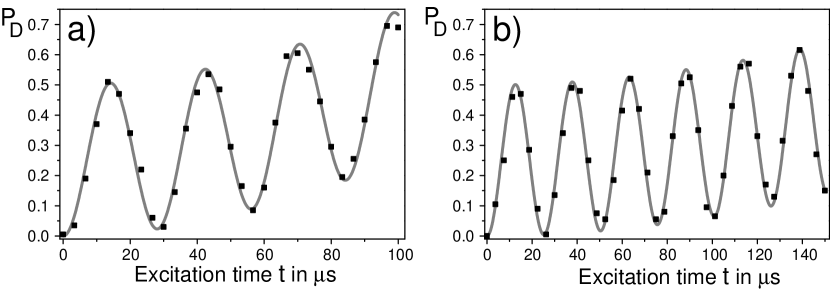
The quality of the addressing can be evaluated from Rabi oscillations between the S and the D state, that are driven on one out of two ions. Residual laser light that reaches the second ion leads to a slow Rabi oscillation of the second ion. From such measurement, we infer the addressing error, i.e. the amount of unwanted qubit rotation on the second ion which is present during a particular one-qubit manipulation on the first ion, and vice versa. Fig. 4 shows two typical excitation patterns for such Rabi flops.
It is important to note that this addressing error does not fundamentally limit the accuracy of one-qubit rotations. For the current experiments, we have included this effect in the error budgetSCHMIDTKALER03 . It is, however, possible to counteract the unwanted rotation on the second ion by an additional laser pulse that is addressed to the second ion. The remaining error on the first ion would then be of second order, and even this contribution could be eliminated by a clever choice of pulses. To make such counteraction possible, one has to determine the phase difference between the laser light addressed directly to ion 1 and the residual light that generates the unwanted rotation on ion 1 while the beam is addressed to ion 2.
We have measured this phase difference with only one ion in the trap. For this, we adjust the beam such that, without deflection, the ion is centrally addressed. Figure 5a shows the dependence of the Rabi frequency on the beam deflection. The corresponding laser intensity is approximately given by a Gaussian with a waist of 2.5 mGULDE_DR . We now perform a spin-echo experiment with the laser frequency tuned to the carrier transition. The two framing pulses are performed with a deflected beam and with the controlled phase set to 0 and , respectively. Because of the beam deflection, the ion feels the laser phase and . The center pulse is directly addressed to the ion, with the controlled phase set to . If we define GULDE03 to be the qubit rotation by an angle about the horizontal axis characterized by the polar angle , where denotes the beam deflection, then the action on the atom can be described by:
| (1) |
If the phase difference between the deflected and the addressed beam is equal to zero, then we expect no spin flip for a phase . Moreover, scanning the phase yields an excitation from the to the state of which can be fitted to infer the phase shift . The dependence of this phase shift on the beam deflection is shown in fig. 5b.
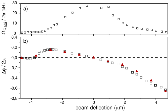
(b)Phase difference between the addressed () and the deflected beam, as perceived at the ion’s position. The different symbols represent independent measurements. The data stem from a measuring period of more than 4 hours.
We attribute the linear part of the phase shift to the elongation of the optical path within the EOD. Such behavior is expected if the laser beam is not ideally aligned with the EOD axis. For beam deflections larger than 2 m, depends no longer in a linear way on the deflection. We suppose that this is due to light which does not travel through the optical system along the ideal path and therefore has a phase different from the Gaussian part of the beam. Such a hypothesis is supported by the small pedestal below the Gaussian profile in fig. 5.
As an important result we note that the phase difference between the deflected and the addressed beam is well defined and stable over long periods of time, even for large deflections. This offers the possibility to reduce the effect of the addressing error in future experiments.
3.3 AC Stark compensation
As the ions which represent the qubits are not ideal two-level systems, the manipulation of the qubit states can be perturbed by non-resonant coupling to other levels. In particular, for manipulations on the vibrational sideband, the coupling to the carrierSTEANE00 is so strong that it induces important light shifts (AC Stark shifts) on the qubit levels. As this would perturb their phases, the light shift needs to be compensated by an additional laser frequency of appropriate power and detuningHAFFNER03 . The compensating light field is generated by a frequency F3, also applied to the double-pass AOM in the 729 nm beam (see section 2.4). Using the same laser beam as a source, this setup ensures that laser power fluctuations or changes in the beam alignment are not converted into phase fluctuations.
3.4 Phase gate and composite laser pulses
The central quantum-logic operation in the Cirac-Zoller CNOT-gate is a one-ion phase gate where the sign of the electronic qubit is switched conditional on the vibrational state. In the computational subspace (, ,, ), this gate is described by a diagonal matrix with the entries (1,-1,-1,-1)252525This transformation is the standard phase gate up to an overall phase factor of ..
Excitation on the blue motional sideband leads to a pairwise coupling between levels except for the level . For the phase gate we perform an effective -pulse on the two two-level systems ( and which changes the sign of all computational basis states except for ). Since the Rabi frequency depends on , we need to use a composite-pulse sequenceCHILDS00 instead of a single blue sideband pulse. The sequence is composed of four sideband pulses and can be described by
| (2) | |||||
where denotes the lower vibrational quantum number of the two coupled states and GULDE03 , similar to in equation 1, denotes a rotation induced by coupling to the upper motional sideband. Figure 6 illustrates the evolution of the Bloch vectors during the phase gate and provides a step-by-step picture of the process262626The Bloch-sphere picture doesn’t give complete information on the phases picked up during the evolution. Those have to be computed using a matrix representation..
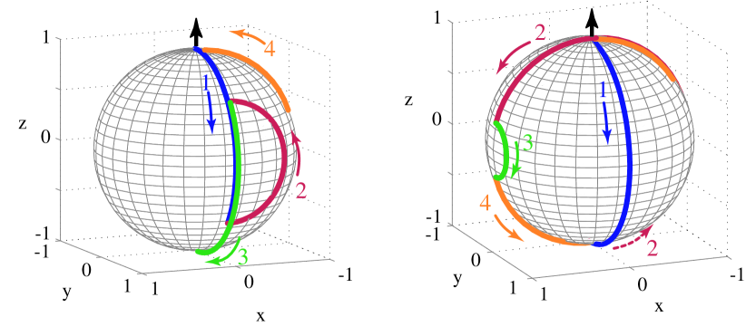
Right: The same laser pulse sequence acting in the subspace. Again, the final state identical to the initial one, except the acquired phase factor .
It may be helpful to interpret this evolution in terms of spin-echos. For the system , the first three pulses constitute a spin-echo experiment where the -pulse in the middle assures that the overall evolution is the one of a -pulse, despite the rotation angle of . This evolution is followed by an additional pulse which completes the -rotation. For the second two-level system , the sequence starts with a -pulse that is followed by the spin-echo-type -rotation.
The phase gate is transformed into a CNOT operation if it is sandwiched in between two carrier pulses, .
3.5 Qubit readout
For detection of the internal quantum states, we excite the S1/2 to P1/2 dipole transition near 397 nm and monitor the fluorescence. This measurement collapses the wave function onto the two states and , fluorescence indicating the S1/2 state, no fluorescence revealing the D5/2 state. By repeating the experimental cycle 100 times we find the average state populations.
By means of an intensified CCD camera, the fluorescence can be monitored separately for each ion. Typical exposure times range from 23 ms (data of fig. 7) down to 10 ms (all other data). The fluorescence is integrated over an area of 3 m x 3 m around the ions’ center, which corresponds to 3 x 3 pixels on the CCD camera. With this method, state detection of each qubit is performed with an accuracy of 0.98, the residual error of 2 resulting from spurious fluorescence light of the adjacent ion (cross-talk) or, in the case of the 23 ms collection time, from spontaneous decay.
If no information on a particular qubit is needed (as in the experiments on the addressing error), we use the signal of a photomultiplier tube to infer the overall state population. In this case, we reduce the exposure time to 3.5 ms.
4 Two-ion universal gate
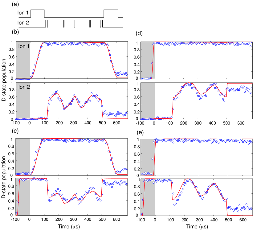
For the two-qubit CNOT operation, Cirac and Zoller proposed to use the common vibration of an ion string to convey the information for a conditional operation (bus-mode)CIRAC95 . Accordingly, the gate operation can be achieved with a sequence of three steps after the ion string has been prepared in the ground state of the bus-mode. First, the quantum information of the control ion is mapped onto this vibrational mode, the entire string of ions is moving and thus the target ion participates in the common motion. Second, and conditional upon the motional state, the target ion’s qubit is invertedMONROE95 . Finally, the state of the bus-mode is mapped back onto the control ion. Note, that this gate operation is not restricted to a two-ion crystal since the vibrational bus mode can be used to interconnect any of the ions in a large crystal, independent of their position.
We realize this gate operationSCHMIDTKALER03 with a sequence of laser pulses. A blue sideband -pulse, , on the control ion transfers its quantum state to the bus-mode. Next, we apply the CNOT operation to the target ion, see sect. 3.4. Finally, the bus-mode and the control ion are reset to their initial states by another -pulse on the blue sideband. We apply the gate to all computational basis states and follow their temporal evolution, see fig. 7. The desired output is reached with a fidelity of 71 to 77%.

If the qubits are initialized in the superposition state control, target, the CNOT operation generates an entangled state . The corresponding data are plotted in fig. 8, left side. At the end of the sequence, near t=500 s, only the states and are observed with =0.42(3) and =0.45(3). The phase coherence of both these components is verified by applying additional analysis /2-pulses on the carrier transition followed by the projective measurement. From the observed populations prior to the analyzing pulses and the contrast of the oscillation, see fig. 9, we calculate the fidelity according to the prescription given in Sackett et al.SACKETT00 , and find a gate fidelity of 0.71(3)SCHMIDTKALER03 .
4.1 Limitations
The gate fidelity is well understood in terms of a collection of experimental imperfectionsSCHMIDTKALER03 . Most important is dephasing due to laser frequency noise and due to ambient magnetic field fluctuations that cause a Zeeman shift of the qubit levelsSCHMIDTKALER03b . As quantum computing might be understood as a multi-particle Ramsey interference experiment, a faster execution of the gate operation would help to overcome this type of dephasing errors. However, a different type of error increases with the gate speed: With higher Rabi frequencies, the off-resonant excitation of the nearby and strong carrier transition is increasingly importantSTEANE00 even if the corresponding phase shift is compensated. Additional but minor errors are due the addressing imperfection, residual thermal excitation of the bus mode and spectator modes and laser intensity fluctuations. In future, higher trap frequencies and the use of hyperfine ground states coupled by Raman transitions for the qubit will improve the gate fidelity.
5 Summary and outlook
We have demonstrated universal single and two-qubit operations on an elementary quantum processor. The results shows the feasibility of ion trap technologies for QC. Recently, tomographic quantum state reconstruction has been implementedROOS03 . For process – or gate – tomography, an appropriate set of initial states and their superpositions may be processed and the output tomographically be analyzed. The application of this technique will allow to fully characterize any kind of quantum evolution and deduce the underlying Hamilton operator. This will help to devise more accurate and more complex quantum operations.
This work is supported by the Austrian ‘Fonds zur Förderung der wissenschaftlichen Forschung’, by the European Commission, and by the ‘Institut für Quanteninformation GmbH’.
References
- (1) M. Nielsen and I. Chuang, Quantum Computation and Quantum Information (Cambridge University Press, Cambridge, 2000).
- (2) P. W. Shor, SIAM J. Sci. Statist. Comput. 26, 1484 (1997), quant-phys/9508027.
- (3) L. K. Grover, Phys. Rev. Lett. 79, 325 (1997).
- (4) E. Jané et al., Quant. Inf. Comp. 3, 15 (2003).
- (5) P. W. Shor, Phys. Rev. A 52, 2493 (1995).
- (6) A. Steane, Proc. R. Soc. Lond. A 452, 2551 (1996).
- (7) A Quantum Information Science and Technology Roadmapping Project by the Advanced Research and Development Activity (ARDA), http://qist.lanl.gov/.
- (8) I. Cirac and P. Zoller, Phys. Rev. Lett. 74, 4714 (1995).
- (9) M. aura and V. Buek, J. Mod. Opt. 49, 1593 (2002).
- (10) Decoherence: Theoretical, Experimental, and Conceptual Problems, Lecture Notes in Physics (eds. Ph. Banchard and D. Giulini and E. Joos and C. Kiefer and I. O. Stammatescu, Springer, 1998).
- (11) F. Schmidt-Kaler, H. Häffner, M. Riebe, S. Gulde, G. P. T. Lancaster, T. Deuschle, C. Becher, C. F. Roos, J. Eschner, and R. Blatt, Nature 422, 408 (2003).
- (12) K. Hayasaka, S. Urabe, and M. Wantanabe, Jpn. J. Appl. Phys. 39, (2000).
- (13) G. P. T. Lancaster, H. Häffner, M. A. Wilson, C. Becher, J. Eschner, F. Schmidt-Kaler, and R. Blatt, Appl. Phys. B 76, 805808 (2003).
- (14) R. W. P. Drever, J. L. Hall, F. V. Kowalski, J. Hough, G. M. Ford, A. J. Munley, and H. Ward, Appl. Phys. B 31, 97 (1983).
- (15) H. Dehmelt, Bull. Am. Phys. Soc. 20, 60 (1975).
- (16) N. Kjaergaard, L. Hornekaer, A. M. Thommesen, Z. Videsen, and M. Drewsen, Appl. Phys. B 71, 207 (2000).
- (17) D. Rotter, Diploma, Univ. Innsbruck (2003).
- (18) S. Gulde, D. Rotter, P. Barton, F. Schmidt-Kaler, R. Blatt, and W. Hogervorst, Appl. Phys. B 73, 861 (2001).
- (19) S. T. Gulde, PhD thesis, Univ. Innsbruck (2003).
- (20) H. Rohde, S. T. Gulde, C. F. Roos, P. A. Barton, D. Leibfried, J. Eschner, F. Schmidt-Kaler, and R. Blatt, J. Opt. B 3, 34 (2001).
- (21) P. K. Gosh, Ion traps (Clarendon press, Oxford, 1995).
- (22) H. Rohde, PhD thesis, Univ. Innsbruck (2001).
- (23) C. Roos, PhD thesis, Univ. Innsbruck (2000).
- (24) D. V. F. James, Appl. Phys. B 66, 181 (1998).
- (25) D. J. Wineland, C. Monroe, W. M. Itano, D. Leibfried, B. E. King, and D. M. Meekhof, J. Res. Natl. Inst. Stand. Technol. 103, 259 (1998).
- (26) C. Roos, Th. Zeiger, H. Rohde, H. C. Nägerl, J. Eschner, D. Leibfried, F. Schmidt-Kaler and R. Blatt, Phys. Rev. Lett. 83, 4713 (1999).
- (27) S. Gulde, M. Riebe, G. P. T. Lancaster, C. Becher, J. Eschner, H. Häffner, F. Schmidt-Kaler, I. L. Chuang, and R. Blatt, Nature 421, 48 (2003).
- (28) A. Steane, C. F. Roos, D. Stevens, A. Mundt, D. Leibfried, F. Schmidt-Kaler, and R. Blatt, Phys. Rev. A 62, 042305 (2000).
- (29) H. Häffner, S. Gulde, M. Riebe, G. Lancaster, C. Becher, J. Eschner, F. Schmidt-Kaler, and R. Blatt, Phys. Rev. Lett. 90, 143602 (2003).
- (30) A. M. Childs and I. L. Chuang, Phys. Rev. A 63, 012306 (2000).
- (31) C. Monroe, D. M. Meekhof, B. E. King, S. R. Jefferts, W. M. Itano, and D. J. Wineland, Phys. Rev. Lett. 75, 4714 (1995).
- (32) C. A. Sackett, D. Kielpinski, B. E. King, C. Langer, V. Meyer, C. J. Myatt, M. Rowe, Q. A. Turchette, W. M. Itano, D. J. Wineland, and C. Monroe, Science 404, 256 (2000).
- (33) F. Schmidt-Kaler, S. Gulde, M. Riebe, T. Deuschle, A. Kreuter, G. Lancaster, C. Becher, J. Eschner, H. H”affner, and R. Blatt, J. Phys. B: At. Mol. Opt. Phys. 36, 623 (2003).
- (34) C. F. Roos, G. P. T. Lancaster, M. Riebe, H. Häffner, W. Hänsel, S. Gulde, C. Becher, J. Eschner, F. Schmidt-Kaler, and R. Blatt , quant-phys/0307210 (2003).