Quantum Imaging Laboratory homepage: ]http://www.bu.edu/qil
Symmetric Autocompensating Quantum Key Distribution
Abstract
We present quantum key distribution schemes which are autocompensating (require no alignment) and symmetric (Alice and Bob receive photons from a central source) for both polarization and time-bin qubits. The primary benefit of the symmetric configuration is that both Alice and Bob may have passive setups (neither Alice nor Bob is required to make active changes for each run of the protocol). We show that both the polarization and the time-bin schemes may be implemented with existing technology. The new schemes are related to previously described schemes by the concept of advanced waves.
pacs:
03.65.Ud, 03.67.Dd, 03.67.Lx, 42.65.KyOf all the capabilities afforded by quantum information science Nielsen and Chuang (2001), quantum key distribution (QKD; for a review, see Ref. Gisin et al. (2002)) currently shows the most promise for practical implementation. Accordingly, there has been a concerted effort to develop QKD schemes that mitigate the technical challenges associated with existing approaches. Among the successes in this effort are the development of autocompensating (alignment-free) schemes for polarization Boileau et al. (2003) and time-bin Muller et al. (1997); Bethune and Risk (1998); Walton et al. (2003a, b) qubits. A further advance is the development of a symmetric scheme for time-bin qubits in which neither Alice nor Bob is required to make active changes to their setups Brendel et al. (1999). Here we use the term symmetric to describe QKD schemes in which a central source distributes some number of photons to both Alice and Bob, such that they share entanglement. This is in contrast to round-trip and one-way configurations, in which the photons move according to BobAliceBob and AliceBob, respectively. In this Letter, we show that symmetry and autocompensation can be combined in a single implementation, for both polarization and time-bin qubits.
This Letter is organized as follows. Beginning with polarization-coded QKD, we first present a round-trip scheme in which autocompensation is achieved by sampling the channel birefringence twice (once on the way from Bob to Alice and once on the way back). Second, we show how Klyshko’s “advanced wave interpretation” (AWI) Belinsky and Klyshko (1992) can be used to transform this round-trip scheme into a one-way scheme imbued with passive detection. Third, we apply the AWI again to obtain a symmetric autocompensating scheme in which both Alice and Bob have passive setups. We then repeat these three steps for time-bin-coded QKD. Finally, we describe feasible implementations of the symmetric autocompensating schemes for both polarization and time-bin qubits.
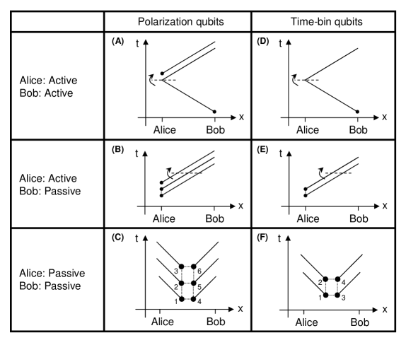
The left column of Fig. 1 shows the space-time diagrams of three autocompensating polarization-coded QKD schemes. For polarization qubits, autocompensating means that the scheme is immune to channel birefringence. The first scheme (Fig. 1A) requires a round trip and is active (both Alice and Bob are required to make changes to their respective setups). The scheme runs as follows. Bob randomly chooses between polarization states and (here, and for the rest of this Letter, we suppress normalization factors), and sends a single photon in that state to Alice. Alice uses a Faraday mirror to reflect that single photon back, and also sends along an auxiliary photon in the state . Alice encodes a single bit by controlling the time ordering of the two photons she sends to Bob. Bob then measures each photon in the basis associated with the state of the initial photon he sent. Without knowing which state Bob sent to Alice, Eve cannot deterministically learn Alice’s bit setting. From Bob’s point of view, the scheme is equivalent to Bennett’s two-state protocol Bennett (1992), since he is attempting to probabilistically distinguish between two nonorthogonal states. The autocompensating feature is derived from the unique property of the Faraday rotator: whatever the polarization transformation along the line from Bob to Alice, the photon that Alice reflects will arrive in Bob’s lab in a polarization state orthogonal to its original state Martinelli (1989).
The AWI was originally conceived as a method for generating one-photon experiments from two-photon experiments. However, we may reverse this procedure and determine which two-photon state embodies the action of Alice’s Faraday rotator. Using Faraday rotation as an example, the AWI associates the single-photon transformation
| (1) |
with the two photon state
| (2) |
In going from Eq. (1) to Eq. (2), the propagation direction for and is reversed. To preserve the handedness of the coordinate system, one of the transverse directions must be reversed as well. This may be accomplished by replacing with . Thus, we see that the AWI associates Faraday rotation with the polarization singlet state .
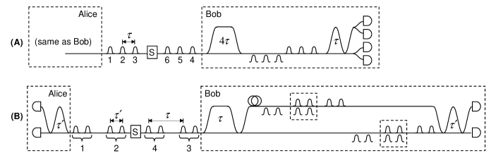
We arrive at the one-way scheme of Fig. 1B by “folding” the input arm of the Faraday rotator of Fig. 1A along the dashed line, thereby replacing a round-trip single-photon space-time diagram with a one-way, two-photon space-time digram (the dotted line connecting the two photons indicates entanglement). What follows is a passive-detection version of the three-photon scheme presented in Ref. Boileau et al. (2003). Alice sends three photons to Bob, with either the first two (case 1), the last two (case 2), or the first and last photons (case 3) in the singlet state, and the other photon vertically polarized. Bob makes his measurements using the passive setup shown on the right side of Fig. 2A. By appropriate postselection, this setup effectively makes a random choice of two out of the three photons, and brings them together on a non-polarizing beamsplitter, which serves to distinguish the singlet state from the other three Bell states Braunstein and Mann (1995). Ignoring the first Mach-Zehnder interferometer (with relative delay ) for the moment, we see that the second interferometer (with relative delay ) enables either the first two, or the last two, photons to meet at the second beamsplitter of this interferometer. If these two photons are in the singlet state, they will leave by opposite ports. The contrapositive is also true: if they leave by the same port (and are detected by one of the pairs of detectors on each output port), then one can infer that they were not in the singlet state. Returning to the first interferometer, we see that this interferometer provides an opportunity for the first and last photons to be analyzed in a similar way. Thus, Bob’s apparatus probabilistically chooses a pair out of the three photons sent by Alice, and determines whether the pair is in the singlet state or in some orthogonal state. Based on his detections, Bob can rule out at most one of the three cases corresponding to Alice’s possible signal states. Therefore, after Bob has made his detection, Alice announces whether the run was a “data run” (cases 1 or 2), or a “test run” (case 3). The data runs are used to share key material (one bit per run) and the test runs are used to monitor the eavesdropper 111One can always convert an active-detection scheme to a passive-detection scheme by using a beamsplitter to probabilistically send the received photon(s) to one of some number of separate detection setups. A drawback of this approach is that the number of optical elements required is increased. The passive schemes described in this Letter, like that in Ref. Brendel et al. (1999), are “intrinsically passive,” in that they achieve passive operation without increasing the number of optical elements required..
We may apply the AWI one more time to get a six-photon symmetric scheme (Fig. 1C) from the three-photon one-way scheme by folding along the dotted line in Fig. 1B. In this scheme, the source produces the six-photon entangled state
| (3) | |||||
In Eq. (3) we use a compact notation that will simplify expressions later in this Letter. The execution of the protocol is similar to the previous case, except that instead of randomly choosing a three photon state and sending it to Bob, Alice uses the same detection setup Bob uses (see Fig. 2A). By inspecting the state in Eq. (3), we see that if Alice determines that photons 1 and 2 are orthogonal to the singlet state, then she knows that photons 5 and 6 are in the singlet state. Similarly, if photons 2 and 3 are orthogonal to the singlet, then photons 4 and 5 are in the singlet state. Alice and Bob can verify that the two terms in Eq. (3) are coherently superposed (as opposed to statistically mixed) by confirming that a certain joint detection (photons 1 and 3 in the singlet state and photons 4 and 6 in the singlet state) never occurs. Since the singlet state is immune to collective birefringence, this scheme, like the round-trip and one-way schemes previously described, is autocompensating.
In the polarization case, only one of the schemes (Fig. 1B) presented has been previously reported. In the time-bin case, the schemes in both Figs. 1D and 1E have been described in Refs. Muller et al. (1997) and Walton et al. (2003a, b), respectively. Therefore, we immediately turn our attention to the symmetric time-bin scheme of Fig. 1F. The source produces the four-photon entangled state
| (4) |
where and stand for early and late, respectively. Alice and Bob each have Mach-Zehnder interferometers with the delay equal to the early/late time interval. On the occasions when all the early photons take the long path and all the late photons take the short path, Alice and Bob announce their measurement results and verify that the proper interference between the two terms in Eq. (4) occurred. On the occasions when at least one of the photons on each side did not follow this earlylong, lateshort pattern, Alice and Bob are able to determine which of the terms in the superposition was realized. In this way they are able to share key material. The scheme is passive because Alice and Bob simply record the time of detection of single photons exiting the two output ports of their respective Mach-Zehnder interferometers. The scheme is autocompensating because, on the occasions when interference occurs between the two terms in Eq. (4), each term picks up the phase associated with two passes through each arm of both interferometers. Thus, the relative phase along the two paths of each interferometer factors out and does not effect the measured results.
It is clear from the states in Eqs. (3) and (4) that the schemes of Figs. 1C and 1F require entangled states involving more than two particles. Since the direct generation of these states is not currently feasible, it is important to determine if the schemes can be adapted to work with some number of separately-entangled photon pairs. This task is particularly straightforward in the polarization case. Using the familiar notation for the four Bell states, and the mode labels in Fig. 1C, we observe
| (5) | |||||
We can express this series of equations in words as follows. Take three separately-entangled photon pairs (each pair in the state ), and, for each pair, send one photon to the left and the other to the right. Perform a Bell-basis measurement on any two photons on the left, and the corresponding pair on the right will collapse into whichever state results from the measurement of the photons on the left. Thus, Alice and Bob can replace the six-photon entangled state of Eq. (3) with three pairs of separately-entangled photon pairs, and implement a symmetric, autocompensating protocol that is closely related to the one-way scheme of Fig. 1B. Specifically, whenever Alice detects a pair of photons in the singlet state, she has effectively prepared the corresponding pair of Bob’s photons in the singlet state. This implementation can be seen as an application of entanglement swapping Zukowski et al. (1993).
Obtaining a feasible version of the time-bin implementation of Fig. 1 is also straightforward. The setup in Fig. 2B shows how Alice and Bob may implement this scheme using separately-entangled photon pairs. Instead of the state in Eq. (4), the source creates the state ; and, instead of a simple Mach-Zehnder interferometer, Bob has the detection setup shown in Fig. 2B. The first interferometer in Bob’s setup allows the first photon to meet the second photon at a non-polarizing beam splitter. By postselecting the occasions when one photon is found to be in each of the small dashed boxes, Bob effectively entangles the two photons sent to him in precisely the way required by Eq. (4). From this point, Alice and Bob each analyze their photons with Mach-Zehnder interferometers, and the scheme proceeds as previously described. This technique can be viewed as the time-bin analog of the polarization-based entanglement distillation experiment described in Ref. Yamamoto et al. (2003).
It is interesting to observe that discoveries in the field of quantum information (entanglement swapping and entanglement distillation) can be naturally related to other areas of quantum information theory (quantum error correction and decoherence-free subpaces) via the AWI, as demonstrated in Fig. 1. Since the central goal of quantum computation is a “folding in time” of a classical computation, the AWI may yield insight into the mechanisms behind the speed-up achieved by certain quantum algorithms.
We have presented symmetric autocompensating QKD schemes that can be implemented with existing technology for both polarization and time-bin qubits. The primary benefit offered by these new schemes is passive operation (neither Alice nor Bob is required to make active changes to their setups). While the schemes make use of existing two-photon sources, it is important to point out that current techniques for producing and detecting multiple photon pairs have very low yields (1 detected four-fold coincidence per second Zhao et al. (2003)).
This work was supported by the National Science Foundation; the Center for Subsurface Sensing and Imaging Systems (CenSSIS), an NSF Engineering Research Center; and the Defense Advanced Research Projects Agency (DARPA).
References
- Nielsen and Chuang (2001) M. A. Nielsen and I. L. Chuang, Quantum Computing and Quantum Information (Cambridge, New York, 2001).
- Gisin et al. (2002) N. Gisin, G. Ribordy, W. Tittel, and H. Zbinden, Rev. Mod. Phys. 74, 145 (2002).
- Boileau et al. (2003) J.-C. Boileau, D. Gottesman, R. Laflamme, D. Poulin, and R. Spekkens, quant-ph/0306199 (2003).
- Muller et al. (1997) A. Muller, T. Herzog, B. Huttner, W. Tittel, H. Zbinden, and N. Gisin, Appl. Phys. Lett. 70, 793 (1997).
- Bethune and Risk (1998) D. S. Bethune and W. P. Risk, IQEC’98 Digest of Postdeadline Papers 12-2 (1998).
- Walton et al. (2003a) Z. Walton, A. F. Abouraddy, A. V. Sergienko, B. E. A. Saleh, and M. C. Teich, Phys. Rev. A 67, 062309 (2003a).
- Walton et al. (2003b) Z. Walton, A. F. Abouraddy, A. V. Sergienko, B. E. A. Saleh, and M. C. Teich, Phys. Rev. Lett. 91, 087901 (2003b).
- Brendel et al. (1999) J. Brendel, N. Gisin, W. Tittel, and H. Zbinden, Phys. Rev. Lett. 82, 2594 (1999).
- Belinsky and Klyshko (1992) A. V. Belinsky and D. N. Klyshko, Laser Phys. (Moscow) 2, 112 (1992).
- Bennett (1992) C. H. Bennett, Phys. Rev. Lett. 68, 3121 (1992).
- Martinelli (1989) M. Martinelli, Opt. Comm. 72, 341 (1989).
- Braunstein and Mann (1995) S. L. Braunstein and A. Mann, Phys. Rev. A 51, R1727 (1995).
- Zukowski et al. (1993) M. Zukowski, A. Zeilinger, M. A. Horne, and A. K. Ekert, Phys. Rev. Lett. 71, 4287 (1993).
- Yamamoto et al. (2003) T. Yamamoto, M. Koashi, S. K. Ozdemir, and N. Imoto, Nature 421, 343 (2003).
- Zhao et al. (2003) Z. Zhao, T. Yang, Y.-A. Chen, A.-N. Zhang, and J.-W. Pan, quant-ph/0302137 (2003).