Rotational Cooling of Polar Molecules by Stark-tuned Cavity Resonance
Abstract
A general scheme for rotational cooling of diatomic heteronuclear molecules is proposed. It uses a superconducting microwave cavity to enhance the spontaneous decay via Purcell effect. Rotational cooling can be induced by sequentially tuning each rotational transition to cavity resonance, starting from the highest transition level to the lowest using an electric field. Electrostatic multipoles can be used to provide large confinement volume with essentially homogeneous background electric field.
pacs:
23.23.+x, 56.65.DyI Introduction
Currently, there are three main techniques to produce translationally cold molecules. The buffer gas [1] and Stark deceleration [2] cooling schemes employ trapping of the low field seekers which requires the molecules to be in the appropriate internal states. Cold molecules produced from photoassociation technique [4] are usually vibrationally hot, occupying a number of high lying vibrational states. Vibrational cooling schemes using optimal control of ultrashort pulses have been proposed [5]. Translationally cold molecules are useful for precision spectroscopy and measurements, molecular optics and interferometry as well as cold collisions studies, although they may be internally hot. It is also desirable to have translationally and internally cold molecules as well if the aim is to obtain molecular Bose-Einstein Condensate [3]. For the purpose of trapping, the molecules need to be cooled internally.
There has been no scheme to rotationally cool molecules although there are several methods of producing molecules in a single rotational state. A classic example is the electrostatic low-J selector which has been used for rotational state selection long ago [6]. Optical Stern-Gerlach has been demonstrated for atoms [7] and molecular state selection by lasers has been proposed [8]. However, these techniques are best applied to molecular beam. They are not cooling schemes since they do not employ a dissipative mechanism. Supersonic expansion is based on dissipation and may also produce rotationally cold molecules, but cannot be used to cool molecules which are already translationally cold since it requires high pressure and can only be applied mechanically on hot molecules. Besides, for translationally cold molecules it is more efficient to employ dissipative process for internal cooling which avoids the loss of molecules.
Recently, we have proposed 1-D translational cooling schemes for molecules which rely on a single optical spontaneous emission [9]. The schemes can be repeated for 3-D cooling if the 1-D cooled molecules can be brought back to the initial internal state again. Molecules in excited rot-vibrational states can redistribute significant amount of the internal energy into the translation motion by state-changing inelastic collisions. At high temperature, this becomes a problem for trapping due to the increased collision rate. Therefore, it is essential to removed the internal excitations by spontaneous emissions fast enough before the inelastic collisions occur. Spontaneous emission carries away entropy to radiation while inelastic collision transfers entropy to the translational degree. For sufficiently dilute heteronuclear molecules, vibrational cooling occur within timescale through infrared spontaneous emissions before the vibrational inelastic collisions take place. Thus, the vibrational entropy is discarded as radiation entropy instead of the translational entropy. However, rotational spontaneous emissions can occur only in polar molecules and take much longer time, beyond the experimental timescale for dilute gas. For dense gas, rotational decay may be enhanced through many-body effect, but inelastic collision rate may become dominantly large.
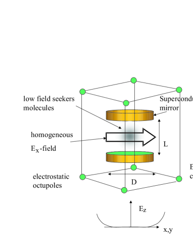
In this paper, we propose a rotational cooling scheme for confined polar molecules. We use external electric field to tune the internal transitions into resonance with a lossy microwave cavity (Fig. 1). This enhances the rotational spontaneous emissions via the Purcell effect [10] whereby the populations are transferred to a lower rotational level in stages and eventually to the ground rotational level. The Purcell effect has been experimentally demonstrated by Goy et. al. using Rydberg atoms in a microwave cavity [11]. The cooling process requires long interaction time and we have proposed a method to confine the molecules within the cavity field.
II Initial State
We consider a gas of polar diatomic molecules at thermal equilibrium temperature with the Maxwell-Boltzmann distribution. We also assume that the gas is sufficiently dilute such that the inelastic collision is negligible throughout the cooling process. At below room temperature, the populations are essentially in the eigenenergy in the ground electronic state Thus, the population and the eigenenergy in the vibrational state and rotational states with (the total electronic angular momentum) are given respectively by
| (1) | |||||
| (2) |
where and are the standard electronic, vibrational and rotational constants (in wavenumber) [12].
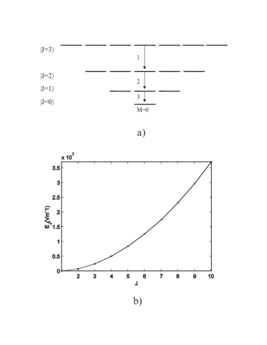
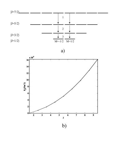
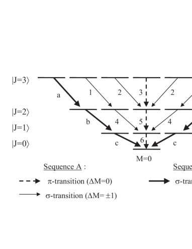
From Eqs. 1 and 2, we estimate that for CsF molecule with ()=()cm-1 [12], only the first 5 rotational levels in the ground vibrational level () are significantly occupied at temperature around . The rotational levels and the magnetic (Zeeman) states for cases and are shown in Fig. 2a and Fig. 3a respectively. Initially, the molecules are in all the magnetic states. In order to cool the molecules in all the magnetic states, the cavity must be able to support linearly polarized as well as circularly polarized photons corresponding to and transitions respectively. If we assume that the cavity supports only linearly polarized photons, only the states with will be sequentially Stark-tuned to cavity frequency by an external static electric field for enhanced spontaneous decay toward the ground level. Molecules in other states (with ) are off-resonance with the cavity and their decays will not be enhanced. In this case, we will have to extract only the molecules in the states for rotational cooling.
III Rotational Cooling Scheme
In this section, we elaborate on the rotational cooling scheme based on the proposed setup apparatus (Figure 1).
A Cooling mechanism
The spacings of rotational levels in polar diatomic molecules increase monotonically with energy levels. We use this monotonic property to bring the populations from the high levels to a low (ground) level by enhanced rotational decay in a lossy microwave cavity. We want to bring each pair of transition ( to with and ) into resonance with the cavity at each time, starting from the transition and ending with the transition. We shall elaborate on the simplest scheme employing only the -transitions () (Figs. 2a and 3a), as well as the scheme which uses multiple polarized cavity for both the - dan -transitions.
B Cavity Enhanced Decay
When the cavity is resonant with the radiative transition from to the decay rate is enhanced, given by the Purcell formula [13]
| (3) |
where is the free space decay rate, the cavity enhancement factor, the dipole transition matrix element, the transition wavelength resonant with the cavity frequency , the quality factor and the effective cavity volume for the Hermite-Gaussian (m,n) transverse mode function
We consider a Gaussian mode in a symmetric confocal resonator (aligned along z-axis, see Fig. 1), we have [14] the cavity spacing for longitudinal mode order , field waist intensity with From these, the effective volume and the enhancement factor is rewritten as
| (4) | |||||
| (5) |
Large enhancement factor is obtained by using a superconducting cavity with large and a low order mode The free and enhanced decay rates are dependent on the and through the numerical factor in the matrix elements.
C Shielding thermal photons
In microwave regime, the mean number of thermal photons is not negligible. It enhances the spontaneous decay rate as However, it reduces the cooling efficiency since the decaying states cannot be completely depopulated due to simultaneous incoherent excitations of the thermal photons. The usual way to reduce the thermal photons is by cooling of the apparatus. The inner surface of the apparatus is coated with microwave photon absorbing material like graphite while the outer surface can also be shielded with a photonic band-gap structure [15]. Thus, we can set and write the free space decay rate for -transition and -transition [16] respectively as
| (6) |
where is the reduced electric dipole matrix element for the vibronic state, and and for the -transition and -transition respectively.
D Electric field tuning
In order to enhance the decay of each transition, we can either tune the cavity or the levels into resonance with each other. In principle, we can construct a tunable cavity by changing the distance between the mirrors. First, the molecules are put into the cavity tuned to enhance the spontaneous emission of the highest rotational state, from to . Then, the cavity is tuned to the next lower transition and so on until all the populations are brought to a single rovibrational state Here, changes from to However, this approach is not very feasible in practice [17].
It is more realistic to tune the transition levels into resonance with cavity frequency using an external electric field. For transitions, photons are most likely to be emitted perpendicular to the dipole. To maximize the molecular dipole-cavity field coupling strength.and the spontaneous decay rate, the dipole should be parallel to the cavity electric field (in x-y plane). Therefore, the tuning electric field is applied along the x-axis so that it aligns the dipole along the cavity field (see Fig. 1). Here, the transitions can be enhanced too as photons are emitted in all directions, although the most probable direction is parallel to the dipole. If the tuning electric field is along the cavity axis, the transition may not be optimumly enhanced because no photon is emitted exactly along the dipole. However, there is still some enhancement from off-axis modes because the microwave cavity is essentially a closed cavity which provides a large solid angle of mode confinement.
A pair of closely spaced electrostatic plates can be introduced into the cavity to produce a tunable homogeneous transverse electric field perpendicular to the cavity axis (say along x-direction) for Stark tuning. Thus, the edges of the superconducting cavity mirrors can be shielded from the strong electric field using a metallic casing or coating to maintain a constant high value.
The energy separation between states and in the electric field is
| (7) |
where and is the electric dipole moment.
From Eq. 7, it is possible to keep a pair of transition at cavity resonance by varying the electric field for each set of . Setting the required electric field for each transition can be predicted as
| (8) |
We need to fix the cavity parameters through such that the argument in the square root is positive. In general, can be positive or negative depending on the transition, so it may not be possible to use a single value of to tune all transitions to cavity resonance. It is only possible to tune those transitions with negative values of (the ’negative signs’ transitions in Figs. 4a and b) to cavity resonance by choosing the cavity parameter which gives a negative nominator in Eq. 8, or in order to obtain real values of . This can be satisfied for and if we set
| (10) | |||||
| (11) |
Condition Eq. 9 applies to the -transitions (Fig. 4a) and the -transitions (Fig. 4b) where are negative. It also applies to although is positive (Fig. 4a) because Eq. 11 vanishes for .
On the other hand, the ”corner” -transitions have positive denominator . The cavity value defined by Eq. 9 gives negative nominator and cannot be used to tune these transitions. The ”corner” transitions and those -transitions (Fig. 4a) with ’positive sign’ can be tuned for cooling by using a different cavity parameter which satisfies a positive nominator in Eq. 8, . A reasonable choice is
| (12) |
and we have
| (13) | |||||
| (14) |
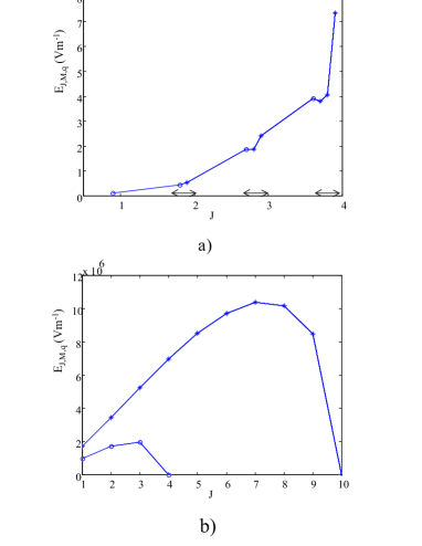
If the cavity only supports linearly polarized photons, only the parallel or - transitions () can be enhanced. For the moment, we consider only the -transitions, from the states to . The transitions are tuned to cavity resonance at each time using the electric field, while all other Zeeman states are not in resonance with the cavity due to the different Stark shifts. Only those molecules in the states are rotationally cooled down to a number of states in the ground level, . For example, with OH molecules in state (Fig. 3a), rotational cooling leads to 2 internal ground states. For spinless molecules like CsF in the ground electronic state (Fig. 2a) the molecules can be cooled to a single internal state, The number of tuning steps required for transitions is for integer , and for half-integer . The tuning electric fields calculated from Eq. 11 are shown in Figs. 2b and 3b for different of the decaying state.
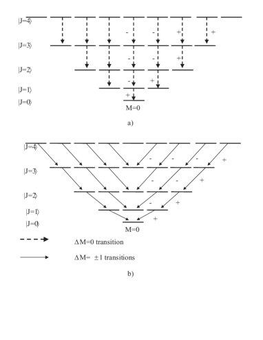
From Figs. 4a and 4b, we see that it is possible establish a scheme to cool the molecules in most states by using a multiple field polarizations cavity which can support all the three polarized photons (linear, and ) corresponding to transitions respectively. This enables the molecules in all the Zeeman states except the ’corner states’ to be Stark-tuned for cooling into a single ground level (or single internal state for case ). Due to the quadratic dependence of the Stark shift on two pairs of states can be Stark-tuned to cavity resonance at each time; but only one pair of states for transition.
The total number of steps for cooling with multiple polarizations is generally given by for integer and for half-integer while the total number of transitions is . The possible sequence of tuning is shown in Fig. 5 for the molecules with spin . The two sequences: A and B correspond to different cavity parameters given by Eq. 9 and Eq. 12 respectively. Sequence A requires steps for integer and steps for half-integer while sequence B requires steps. Sequence A cools times more states than sequence B but the transitions of both sequences are complementary. The tuning electric fields for sequence A and sequence B are calculated from Eq. 11 and Eq. 14 as shown in Figs. 6a and 6b respectively.
E Doppler broadening
The cavity linewidth must be larger than the maximum Doppler shift in order for the moving molecules to stay in resonance with the cavity For thermal ensemble of OH molecules at about , the maximum quality factor we can use is This value just gives the highest enhancement factor in the bad cavity regime. So, it is not helpful to use larger The momentum distribution of the molecules is essentially unaffected by the small microwave photon recoil momentum from rotational spontaneous emissions unless the molecules are ultracold.
F Confinement
The maximum diameter (radial dimension) for confocal cavity geometry can be estimated as (see Fig. 1). For a typical microwave cavity dimension of and molecules with velocity of say the interaction time of is much shorter than the enhanced lifetime. Therefore, we need to confine the molecules within the cavity.
Figure 1 shows the proposed rotational cooling apparatus with cavity and electric octupoles. Higher order electrostatic poles can be used to confine the low field seekers with kinetic energy below about 1K [18]. This background field also prevents the Majorana flop into untrapping state.
It may be possible to confine molecules using a non-stick solid material like teflon which has low surface adhesion to certain molecules. However, this is only applicable to room temperature gas and not translationally cold gas because collisions with the solid wall will lead to translational thermalization. Since the molecules in the solid material do not rotate and have no angular momentum, collisions with the surface do not cause rotational transition via conservation of angular momentum. The main advantage of solid material confinement is of course the infinitely long trapping time.
G Numerical estimates
We estimate the cooling time with typical applied tuning field for two types of molecules only for the -transitions involving the middle states (). First, we consider molecules in state (Fig. 2a) with and and the electric dipole moment Debye [21]. The required electric field is in the order of (Fig. 2b). The cavity spacing from Eq. 9 is for mode order The cavity diameter is If the distance between opposite electrostatic poles which produces the homogeneous electric field is the required voltage is around The free space decay rate is and for the enhancement factor of boost the decay rate to Supposing that a duration of is allocated for each stage of decay from level then the total duration for enchanced decay from to is ( minutes). Since the trapping volume is macroscopically large, many molecules can be confined and this allows the use of sufficiently dilute gas to reduce loss rate of molecules due to state changing collisions. Due to the absence of Majorana flop, a significant number of molecules should remain confined for long enough time for the rotational cooling to take place.
Next, we estimate the essential cooling parameters using OH molecules (with the levels in Fig. 3a), which has a large rotational constants and [19], and the static dipole moment of [20]. From Fig. 3b, we find that the required electric fields are around Even for cavity dimension of the required voltage is very large and the free space decay rate is For a small and assuming we have and
For OH, the required electric field may be too large to be realized in practice and it is due to the unusually large rotational constant However, it requires a small cavity Q and the cooling time can be considerably shortened if the highest Q in the bad cavity regime is used.
IV Conclusions
We have proposed a rotational cooling scheme for polar molecules using Stark-tuned internal levels in a superconducting microwave cavity. Homogeneous electric field is applied for Stark tuning each transition to cavity resonance to enhanced rotational spontaneous emissions. Sequential tuning and the use of the cavity which supports multiple field polarizations enables all molecules to be cooled towards the ground rotational level. Numerical estimates for molecules show that the scheme requires high voltage which can be realized using the state-of-the-art technology. However, molecules with unusually large rotational constants requires electric field beyond the current capability. The typical cooling time of one minute with a large Q enhancement in dissipative cavity regime can be realized for most molecules with moderate rotational constant and large dipole moment.
ACKNOWLEDGMENTS
I gratefully acknowledge support from Deutsche Forschungsgemeinschaft (Forschergruppe Quantengase) and Optik Zentrum Konstanz. I thank Dr. Pepijn Pinkse and Prof. Rempe for hospitality at MPQ where the idea emerged; Priv. Doz. Dr. Peter Marzlin and Prof. Juergen Audretsch; and Dr. MacAdam for introducing the Stark ball device. I also thank the referee for suggesting the extension of the scheme using multiple polarized cavity.
REFERENCES
- [1] J. D. Weinstein, R. deCarvalho, T. Guillet, B. Friedrich, and J. Doyle, Nature (London) 395, 148 (1998).
- [2] Hendrick L. Bethlem, Giel Berden, Floris M. H. Crompvoets, Rienk T. Jongma, J. A. van Roij and Gerard Meijer, Nature, Vol. 406, August 2000.
- [3] Physics News Update, Number 581, March 22 (2002).
- [4] Y. B. Band and P. S. Julienne, Phys. Rev. A 51, R4317 (1995).
- [5] S. G. Schirmer, Phys. Rev. A 63, 13407 (2000).
- [6] H. K. Hughes, Phys. Rev. 72, 614 (1947).
- [7] Sleator et. al. , Phys. Rev. Lett. 68, 1996 (1992).
- [8] P. Domokos, T. Kiss, and J. Janszky, Eur. Phys. J. D 14, 49-53 (2001).
- [9] C. H. Raymond Ooi, Karl-Peter Marzlin and Jürgen Audretsch, Laser Cooling of Molecules via Single Spontaneous Emission, Eur. Phys. J. D 00227-7 (2002).
- [10] E.M. Purcell, Phys. Rev. 69, 681 (1946).
- [11] P. Goy, J. M. Raimond. M. Cross, and S. Haroche, Phys. Rev. Lett. 50, 1903 (1983).
- [12] G. Herzberg, Molecular spectra and molecular structure. I. Spectra of diatomic molecules, 1950, D. van Nostrand Co. (Toronto).
- [13] Marlan O. Scully and Muhammad Suhail Zubairy, Quantum Optics, Cambridge: Cambridge University Press, 1997.
- [14] Amnon Yariv, Quantum electronics, New York: Wiley, 1989.
- [15] Christopher M. Cornelius and Jonathan P. Dowling, Phys. Rev. A 59, 4736 (1999).
- [16] Harold W. Kroto, Molecular rotation spectra, London: Wiley, 1975.
- [17] communications with Dr. Pepijn Pinkse in MPQ.
- [18] A a Stark ball device has been developed (K.B. MacAdam and C.S. Hwang, ”The Stark ball: A programmable multipolar environment”, Rev. Sci. Instrum. 74, 2267 (2003)). The device can provide confinement for the molecules in three dimensions in a large volume of homogeneous or zero electric field. This device is ideal for our purpose. It uses 16 electrostatic rods organized in spherical symmetry and with versatile electronics control of electric field profiles.
- [19] Aleksandr A. Radzig and Boris M. Smirnov, Reference data on atoms, molecules and ions, (Springer series in chemical physics ; 31 ), Springer-Verlag Berlin Heidelberg 1985.
- [20] W. L. Meerts and A. Dymanus, Chem. Phys. Lett. 23, 45 (1973).
- [21] Robert M. Hill and Thomas F. Gallagher, Phys. Rev. A 12, 452 (1975).