[
Control of conditional pattern with polarization entanglement
Abstract
Conditional interference patterns can be obtained with twin photons from spontaneous parametric down-conversion and the phase of the pattern can be controlled by the relative transverse position of the signal and idler detectors. Using a configuration that produces entangled photons in both polarization and transverse momentum we report on the control of the conditional patterns by acting on the polarization degree of freedom.
pacs:
42.50.Dv, 42.65.Lm]
I Introduction
Spatial optical patterns have been subject of interest along the development of classical and quantum optics. For the case of the light produced in parametric down-conversion, spatial patterns are present in tranverse correlation functions[2, 3] and distribution of quantum fluctuations[4]. These spatial patterns have been demonstrated to carry information about coherence properties[5], mode structure[6], and orbital angular momentum[7], for example.
Most of the observations of quantum effects in optics rely on conditional measurements[8]. Conditional interference patterns in the fourth-order correlation function have been observed with twin photons produced by spontaneous parametric down-conversion in several experiments[3, 9, 10, 11, 12, 13, 14]. For the case of spatial patterns, diffracting masks placed along the propagation of the beams are very often used[3, 10, 11, 12]. The conditionality is observed by varying the relative transverse position between signal and idler detectors. Here we focus on the configuration described in Ref.[14] that allows generating spatial patterns without diffracting masks and to prepare a state which is simultaneously entangled in polarization and transverse momentum with controlled degree of entanglement. The entanglement in transverse momentum leads to a quantum interference, that can be revealed through conditional spatial patterns[13]. This interference pattern have been demonstrated to be useful to measure the degree of entanglement in polarization[14] and to manipulate the entanglement in transverse momentum through the polarization [15]. In this work we demonstrate experimentally the control of the conditional spatial pattern by acting on the polarization degree of freedom.
II Theory
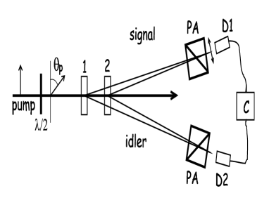
Consider the situation sketched in Fig.1. Two non-linear crystals are pumped by the same laser beam and at the detection plane, signal and idler beams originating at different crystals overlap. The laser beam is 45 degrees polarized to pump equally both crystals. One of the crystals produce twin photons linearly polarized in the horizontal direction(H) and the other vertically polarized(V) twin photons. The strength of the pump interaction with each crystal can be controlled by a halfwave plate acting on the laser beam polarization. Before detectors, polarization analyzers projects all beams onto 45 degrees linear polarization. The signal beam passes through a halfwave plate before the analyzer. Therefore, just before detection, the state of the field can be written as:
| (1) | |||
| (2) |
where and are coefficients taking into account the strength of the pump beam in each polarization direction (H and V) and normalization. is the angle between the polarization of the signal beam after the halfwave plate and the horizontal direction. is the phase difference between the two states and i(s)1(2) refer to signal(s) and idler(i) beams originated in crystals 1 and 2. The phase difference associated to the different possible paths for the beams can be better understood considering them coming from the field propagation, as in Ref.[13], but it can also be considered in the state as well. This phase difference gives rise to the conditional interference patterns of our interest.
The coincidence counting rate is given by:
| (3) | |||
| (4) |
As we can see, the coincidence rate has an oscillating behavior depending on the polarization angle of the signal beam and on the phase difference .
From the above it is seen that actions on the halfwave plate(in the signal beam) affects the degree of entanglement and therefore the visibility of the patterns. However, even for maximally entangled states, it is possible to change the phase of the interference pattern, by choosing an angle which changes the sign of the function in the last term of Eq.3.
III Experiment
The experiment have been performed with two 1cm long LiIO3(Lithium Iodate) nonlinear crystals cut for type-I phase matching pumped by a He-Cd laser operating at 442nm as depicted in Fig.1. The separation between the crystals is about 1cm. The polarization of the pump beam is turned into 45 degrees from the horizontal direction by a halfwave plate before the crystals. The optical axes of the crystals are aligned so that the first crystal is pumped by the horizontally polarized component and the second crystal is pumped by the vertically polarized component. Signal and idler photons at 884nm are detected before passing through polarizing beam splitters, interference filters with 10nm bandwidth and entrance slits. Before the signal polarizing beam splitter, a halfwave plate is used for rotating the input polarization. The detectors are avalanche photodiode photon counting modules placed about 1m from the crystals.
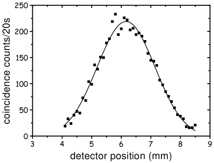
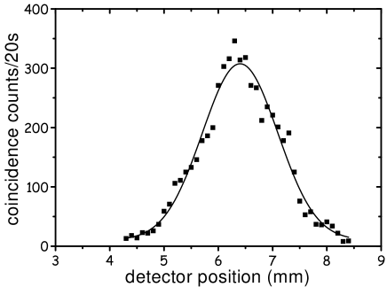
We have measured the coincidence profile for the photons originating in each crystal. For doing so, the pump beam polarization is first oriented vertically, so that it only pumps the first crystal. The signal detector is horizontally scanned while the idler detector is kept fixed. The polarization analyzers(waveplate and polarizing beam splitters) were both oriented to 45 degrees transmission. The scan is performed with a 0.2mm slit in the detector entrance. The result is shown in Fig.2. The procedure is repeated when the pump beam polarization is oriented horizontally, in order to only pump the second crystal. The result is shown in Fig.3. Gaussian fittings to these curves indicate the position of the peaks at xc=6.2mm and xc=6.4 mm, respectively. This shows that the twin photons from both crystals are correlated around the position xc=6.3mm of the signal detector when the idler detector is fixed.
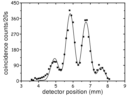
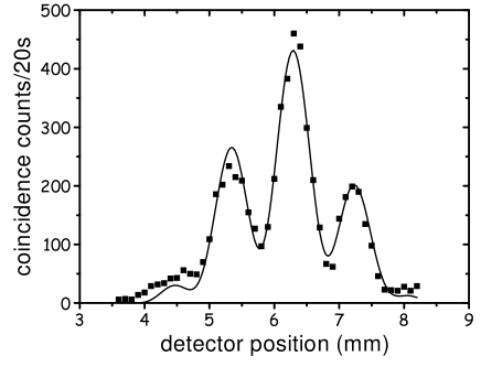
Now, the pump beam polarization is set to 45 degrees, so that it pumps both crystals with the same strength. Performing the horizontal scan with signal detector as before, and leaving both polarization analyzers oriented to 45 degrees, we obtain the spatial pattern shown in Fig.4. At the position around xc=6.3mm the coincidence counting rate is much lower than that for twin photons originating in each crystal individually.
The second step is to demonstrate that acting on the polarization, the pattern can be changed. For doing so the waveplate in the signal beam is turned 45 degrees and the input state arriving at the polarizing beam splitters is changed from:
| (5) |
to
| (6) |
Fig.5 shows the coincidence profile scanning signal detector and keeping idler detector fixed in the same position of the previous measurement. Now at the position around xc=6.3 mm there is a coincidence peak instead of a valley. Using the usual double-slit diffraction function to fit the experimental data we found the visibilities of the patterns showed in Fig.4 and 5 to be 64% and 62%, respectively.
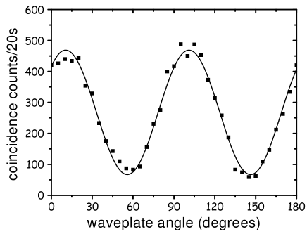
To show that the polarization entanglement is present together with transverse momentum a Bell type measurement have been performed. Fig.6 shows interference fringes scanning the halfwave plate angle and signal detector fixed at xc=6.3 mm presenting 75% visibility. This measurement is enough to demonstrate entanglement without perform a complete Bell measurement and show that some Bell inequality is violated. This kind of source of polarization entangled states have been demonstrated to produce all family of Bell states with good quality in a configuration with 1mm separated two thin crystals[16].
IV Discussion
The interference patterns presented in Figs.4 and 5 show that the phase of the conditional interference pattern can be controlled by changing the input polarization state at the analyzers. This is a consequence of the coupling between polarization and transverse degrees of freedom of the twin photons. As the interference is conditioned to the detection at the idler side, the phase, visibility and even the length of the oscillations obtained by the displacement of the signal detector, depend on the idler detection properties[13]. In the case presented above, the idler detection properties were kept fixed, so that only the polarization state was changed.
In order to observe this effect, the presence of the polarization analyzers, is required before detectors. This means that the polarization gives us control over the spatial correlation between twin photons by post-selection. In our measurements we were able to pass from anti-correlation to correlation in the position corresponding to the individual(i.e. for each crystal independently) coincidence peaks.
In fact, for the usual double-slit experiment with single photons and intensity measurements, it is possible to have a similar control over the phase of the pattern. For doing that, we could place waveplates in each one of the slits and perform the measurement of the intensity pattern after some linear polarization analyzer. The principle for acting on the phase of the pattern is the same, but the consequences are different. When we act on the phase of a conditional pattern, we are actually changing the spatial correlation between photons. For instance, a collinear version of our set-up with signal and idler having transverse coordinates with opposite sense, the change in the phase of the pattern would imply in the switching from bunching to anti-bunching spatial statistics, in the same fashion as it was done in Ref.[17].
V Conclusion
In conclusion, we have demonstrated experimentally how to control the phase of a conditional interference pattern, manipulating the polarization degrees of freedom of a state of the electromagnetic field entangled in transverse momentum and polarization. This kind of manipulation opens possibility to control properties of the field state in a given degree of freedom conditioned to the action on another one. It also suggests that it is possible to prepare special states of the light with controlled statistics.
Acknowledgements.
Financial support was provided by Brazilian agencies CNPq, PRONEX, FAPERJ, FUJB and Institutos do Milênio-Informação Quântica.REFERENCES
-
[1]
Corresponding author.
E-mail address: dilson@if.ufrj.br
- [2] G. A. Barbosa, Phys. Rev. A 54, 4473 (1996); P. H. Souto Ribeiro, S. Pádua, and C. H. Monken, Phys. Rev. A 60, 5074 (1999).
- [3] C. H. Monken, P. H. Souto Ribeiro and S. Pádua, Phys. Rev. A 57, 3123 (1998).
- [4] I. Marzoli, A. Gatti, and L. A. Lugiato, Phys. Rev. Lett. 78, 2092 (1997).
- [5] P. H. S. Ribeiro, C. H. Monken, and G. A. Barbosa, Appl. Opt. 33, 352 (1993); P. H. S. Ribeiro, S. Pádua, J. C. Machado da Silva and G. A. Barbosa, Phys. Rev. A 49, 4176 (1994); P. H. Souto Ribeiro, S. Pádua, J. C. Machado da Silva, ans G. A. Barbosa, Phys. Rev. A 51, 1631 (1995); E. J. S. Fonseca, C. H. Monken, S. Pádua, and G. A. Barbosa, Phys. Rev. A 59, 1608 (1999).
- [6] M. Vaupel, A. Maître, and C. Fabre, Phys. Rev. Lett. 83, 5278 (1999); S. Ducci, N. Treps, A. Maître, and C. Fabre, Phys. Rev. A 64, 023803 (2001).
- [7] D. P. Caetano, M. P. Almeida, P. H. Souto Ribeiro, J. A. O. Huguenin, B. Coutinho dos Santos, and A. Z. Khoury, Phys. Rev. A 66, 041801 (2002).
- [8] See, for example, Z. Y. Ou, X. Y. Zou, L. J. Wang, and L. Mandel , Phys. Rev. Lett. 65 , 321 (1990); Z. Y. Ou, X. Y. Zou, L. J. Wang, and L. Mandel, Phys. Rev. A 42, 2957 (1990); A. G. Zajonc, L. J. Wang, X. Y. Zou, and L. Mandel, Nature (London) 353, 507 (1991); P. G. Kwiat, W. A. Vareka, C. K. Hong, H. Nathel and R. Chiao, Phys. Rev. A 41, 2910 (1990); X. Y. Zou, L. J. Wang, and L. Mandel, Opt. Commun. 84, 351 (1991); A. M. Steinberg, P. G. Kwiat and R. Chiao Phys. Rev. A 45, 6659 (1992); A. Zeilinger, Rev. Mod. Phys. 71, S288 (1999).
- [9] R. Ghosh and L. Mandel, Phys. Rev. Lett. 59, 1903 (1987).
- [10] E. J. S. Fonseca, C. H. Monken, and S. Pádua, Phys. Rev. Lett. 82, 2868 (1999).
- [11] E. J. S. Fonseca, J. C. Machado Silva, C. H. Monken, and S. Pádua, Phys. Rev. A 61, 023801 (2000).
- [12] E. J. S. Fonseca, Z. Paulini, P. Nussenzveig, C. H. Monken, and S. Pádua, Phys. Rev. A 63, 043819 (2001).
- [13] P. H. Souto Ribeiro, Braz. J. Phys. 31, 478 (2001).
- [14] M. França Santos, P. Milman, A. Z. Khoury, and P. H. Souto Ribeiro, Phys. Rev. A 64, 023804 (2001).
- [15] D. P. Caetano and P. H. Souto Ribeiro, Opt. Commun. 211, 265 (2002).
- [16] P. G. Kwiat, E. Waks, A. G. White, I. Appelbaum, and P. H. Eberhard; Phys. Rev. A 60, 773 (1999);
- [17] W. A. T. Nogueira, S. P. Walborn, S. Pádua, and C. H. Monken, Phys. Rev. Lett. 86, 4009 (2001); W. A. T. Nogueira, S. P. Walborn, S. Pádua, and C. H. Monken, Phys. Rev. A 66, 053810 (2002).