Quantum communications with time-bin entangled photons:
long distance quantum teleportation and quantum repeaters
Abstract
Using 2 km of standard telecom optical fibres, we teleport qubits carried by photons of 1.3 m wavelength to qubits in another lab carried by a photons of 1.5 m wavelength. The photons to be teleported and the necessary entangled photon pairs are created in two different non-linear crystals. The measured mean fidelity is of 81.2%. We discuss how this could be used as quantum repeaters without quantum memories.
I Introduction
Long distance quantum communication in optical fibers should
exploit the standard and widely installed telecom fibers. This
standard imposes the wavelength (either around 1300 nm, or around
1550 nm). It does also strongly suggest that polarization encoding
is not the optimal choice. Indeed, polarization effects in telecom
fibers fluctuate on a time scale from ms to tens of minutes for
aerial and underground cables, respectively. These unavoidable
fluctuations require active feedback and/or compensation schemes.
An alternative consists in encoding the qubits in time-bins.
Time-bin qubits have already been used for quantum
cryptographyTittelQC , for the production of non-maximally
entangled qubitsThewRobust and to encode quantum states in
higher dimensional Hilbert spacesHighDim . In this
contribution we present the results of an experimental
demonstration of long distance quantum teleportation, using
time-bin qubits. In section III we present a
potential application of quantum teleportation as ”quantum
repeaters without quantum memory”.
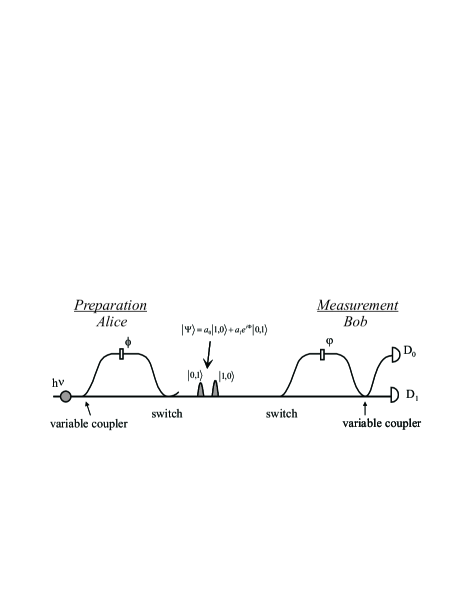
Figure 1 presents a general preparation and measurement scheme for time-bin qubitsTittelWeihs . In principle, any state can be deterministically prepared and ideal measurements in any basis performed. In practice, however, the switches are replaced by passive couplers, hence induce 50% loss. Also, in our experiment we replaced the variable coupler either by a passive coupler (corresponding to a coupling ratio of 50%), or by fibers of appropriate lengths (corresponding to 0% and 100% coupling ratios)LABEL:comment1.
II Quantum teleportation
Our experiment is schematically presented on Fig. 2. For a general introduction to quantum teleportation and previous experiments, we refer toBennetTelep ; ViennaTelep ; RomeTelep ; ShiTelep ; KimbleTelep .
A mode locked Ti:Sapphire laser produces 150 fs pulses at nm. The laser beam is split into two parts. The transmitted beam is used to create entangled time-bin qubits (EPR source) by passing the beam first through an unbalanced bulk Michelson interferometer with optical path-length difference ns and then through a type I non-linear crystal (LBO) where entangled non-degenerate collinear time-bin qubits at telecom wavelengths (1310 and 1550 nm) are created. The pump light is removed with a silicon filter (SF) and the twin photons are collimated into an optical fibre and separated by a wavelength-division-multiplexer (WDM). The 1310 nm photon is then sent to Charlie and its twin 1550nm photon to Bob. The entangled state is described by , where and represents the first and second time-bin, respectively.
The reflected beam is used to create the qubits to be teleported. Similar to the creation of the entangled pairs, the beam is focussed into a LBO crystal creating pairs of photons at 1310 nm and 1550 nm wavelengths. After blocking the pump light and coupling the photon pairs into an optical fibre, the 1550 nm photon is removed using a WDM. Alice passes the 1310 nm photon through a qubit preparation device, thereby creating a state , where or and . Alice’s qubit is finally sent to Charlie.
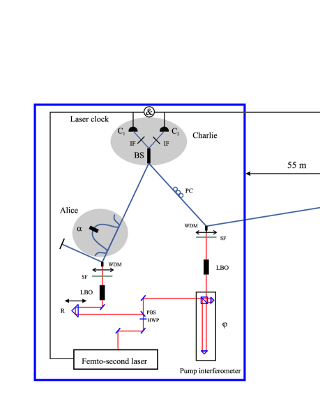
Charlie performs the joint Bell-state measurement between the qubit sent by Alice and his part of the pair, with the 50/50 fibre coupler BS. We select only the projection onto the singlet entangled state . This takes place when the two photons trigger the detectors labelled C1 and C2 on Fig. 2 at times that differ precisely by the time difference between two time-bins. Detectors C1 and C2 are a cooled passively quenched Ge avalanche photodiode (APD) and a Peltier cooled InGaAs APD respectivelyidQ . Bob is situated in another lab, 55 m away from Charlie. To simulate a longer distance we added 2 km of optical fibre before the teleported photon reaches Bob’s analyser.
The quality of the teleportation is usually reported in terms of fidelity , i.e. the probability that Bob’s qubit successfully passes an analyser testing that it is indeed in the state prepared by Alice, averaged over all possible . The linearity of quantum mechanics implies:
| (1) |
where and , are the fidelities averaged only over the states corresponding to the equator and the poles of the Poincaré sphere, respectively.
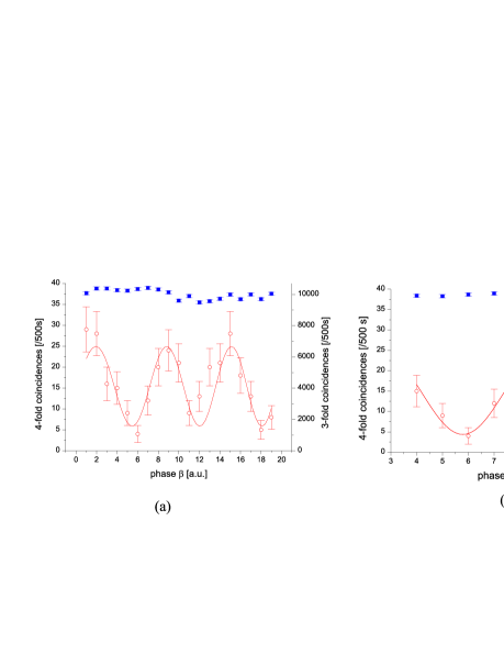
In our experiment we measured directly, by preparing and measuring each of the two corresponding states: . In order to measure , we prepared various states, using a 50/50% coupler with various phases , and for each scanned the analyzing interferometer’s phase . From the raw visibility one obtains the fidelity . Typically, we obtain (Fig. 3a), with best results achieving values up to (Fig. 3b). Accordingly, the measured fidelity, averaged over all possible states equals .
III Quantum repeaters without quantum memories
Generally, quantum channels are lossy, hence the probability that a single photon sent by Alice reaches Bob decreases with distance. Because of the no-cloning theorem, there is no way to merely amplify the signal. With noise-free detectors, the attenuation would only affect the bit rate, and protocols like quantum cryptography would provide secure keys for arbitrary distances. However, realistic detectors have a finite probability of dark counts (around per ns for InGaAs APDsidQ ). This noise is independent of the distance, hence there is a limiting distance after which the signal becomes smaller than the noise. In a series of papers, H. Briegel and co-workersBriegel have shown that the appropriate use of entanglement purification and of quantum memories allows one, in principle, to realize quantum repeaters which would extend the range of quantum cryptography to unlimited distances, with only a polynomial increase of repeater stations. This is a promising line of research for experimental physics, but it is only fair to say that it will remain a research topic for the years to come.
However, without quantum memories and using only near future technologies (like the ones presented in this contribution), there are ways to extends the distances over which secret quantum keys can be distributed, although not to unlimited distancesrmp ; YamamotoQR ; FransonQR . Assume that Alice and Bob are connected by a quantum communication channel with transmission coefficient . Denote the photon counting detector’s efficiency and the dark count probability per transmission (i.e. per qubit). Furthermore, denote and the rates of correctly and incorrectly detected photons: In good approximation111We checked that a complete analysis doesn’t change qualitatively the results, we have , . Accordingly, the total rate of transmission and the QBER (Quantum Bit error Rate) read:
| (2) |
The net rate , after error correction and privacy amplification, is proportional to the raw rate with a coefficient that depends on the rmp . This coefficient is the difference between the Alice-Bob and the Alice-Eve mutual Shannon informations (or the Bob-Eve one, if smaller). The exact relation between and the QBER depends on the exact eavesdropping model. Our results are essentially independent of the details, though numerical values may slightly differ. For the optimal individual attack, is almost a linear function of the QBER, hence we use the approximation:
| (3) |
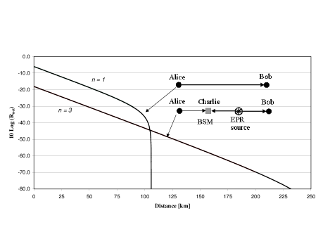
With realistic numbers, , , and an attenuation coefficient dB/km (i.e. , fiber length), this sets an absolute limit for quantum key distribution around 105 km (even with perfect single photon sources), see Fig. 4. Consider now the case where the channel is divided into 3 sections, each of length , i.e. with transmission coefficient (Fig. 4), exactly as in a quantum teleportation experiments. In such a configuration, Bob correctly detects the qubit whenever all 3 photons make it to their detectors, all 3 detectors click and the Bell measurement is successful, i.e. . The rate of incorrect detections contains three parts222We assumed that the detector noise completely dominates the error rate. This is a reasonable assumption when Alice is directly connected to Bob (i.e. when ), seestucki02 . But, clearly, when the systems gets more complex, optical alignment is less optimal. How this optical contribution to the error rate scales with depends on the detailed implementation. From our experiment we believe that the ”optical error rate” can be maintained quite low.: (i) all 3 photons are lost and there are 3 dark counts, (ii) 2 photons are lost, 1 detected and there are 2 dark counts, (iii) 1 photon is lost, 2 detected and there is one dark count. Accordingly:
| (4) | |||||
The corresponding net rate, with the same parameters, is also displayed on Fig. 4. Clearly, the division of the channel into 3 trunks and the use of teleportation increases significantly the maximal distance over which quantum key distribution is possible. The generalization to divisions into n trunks is straightforward. For given parameters the limiting distance increases with n, up to a maximum, and then decreases again.
IV Concluding remarks
Objects are constituted by energy and structure (or matter and
form according to Aristotle). In quantum teleportation one does
not teleport neither energy nor matter. However, the ultimate
structure of objects is indeed teleported from and place to
another, without the object ever being anywhere in between!
Admittedly, teleportation of systems much more complex than a
simple qubit is still elusive. But the teleportation of qubits
could already be useful for quantum cryptography, though much
effort still have to be devoted to improve the results of this
first long distance realization, especially the stability of the
experimental scheme.
Financial support by the Swiss OFES and NSF within the framework of the European IST project Qucomm and the Swiss National Center for Quantum Photonics is acknowledged. W.T. acknowledges funding by the ESF Programme Quantum Information Theory and Quantum Computation (QIT).
References
- (1) W. Tittel, J. Brendel, H. Zbinden and N. Gisin, Phys. Rev. Lett. 84, 4737, 2000.
- (2) R. Thew, S. Tanzilli, W. Tittel, H. Zbinden, N. Gisin, Phys. Rev. A 66, 062304 (2002).
- (3) H. de Riedmatten, I. Marcikic, H. Zbinden and N. Gisin, Quant. Inf. Comput. 2425-433 (2002); and these proceedings.
- (4) W. Tittel and G. Weihs, Quantum Information & Computation, 1, 3, 2001.
- (5) The replacement of the switches is necessary because real and fast switches have losses even larger than 50. However, real variable couplers could be used.
- (6) C.H. Bennett, G. Brassard, C. Crépeau, R. Jozsa, A. Peres, and W.K. Wootters, Phys. Rev. Lett. 70, 1895, 1993.
- (7) D. Bouwmeester, J.W. Pan, K. Mattle, M. Eibl, H. Weinfurter, and A. Zeilinger, Nature390, 575, 1997.
- (8) D. Boschi, S. Branca, F. De Martini, L. Hardy, and S. Popescu, Phys. Rev. Lett.80, 1121, 1998.
- (9) Y.-H. Kim, S. P. Kulik, and Y. Shih, Phys. Rev. Lett. 86, 1370, 2001.
- (10) A. Furusawa, J. L. S rensen, S. L. Braunstein, C. A. Fuchs, H. J. Kimble, and E. S. Polzik, Science 282, 706, 1998.
- (11) D. Stucki, G. Ribordy, A. Stefanov, and H. Zbinden, J. of Mod. Optics 48, 1967, 2001. Available from www.idQuantique.com.
- (12) H. Briegel, W. Dur, J.I. Cirac, and P. Zoller, Phys. Rev. Lett. 81, 5932, 1998.
- (13) N. Gisin, G. Ribordy, W. Tittel, and H. Zbinden, Rev. Mod. Phys. 74, 145, 2002.
- (14) E. Waks, A. Zeevi, and Y. Yamamoto, Phys. Rev. A 65, 052310, 2002.
- (15) B. C. Jacobs, T. B. Pittman, J. D. Franson, Phys. Rev. A 66, 052307 (2002)
- (16) D. Stucki, N. Gisin, O. Guinnard, G. Ribordy, H. Zbinden, New J. of Phys. 4, 41.1-41.8 (2002).